Description of the Warthog Robotics SSL 2017 Project
Rafael G. Lang, Guilherme C. de Oliveira, Heloisa J. Barbosa, Níc olas dos S. Rosa, Bruno C. Henriques, Anderson H. de Siqueira, Ivan N. da Silva, Roseli A. F. Romero
Warthog Robotics University of São Paulo at São Carlos
Abstract This paper presents the main modifications since the last Team Description Paper of Warthog Robotics and a general explanation of the current project, presenting RoboCup SSL team WR Magic, developed since 2011 by the Warthog Robotics group from the University of São Paulo at São Carlos. This project merges the best features from older projects developed by the groups GEAR and USPDroids. The mechanical structure is a mixed design using aluminum and composite materials and contains four DC motors for locomotion. The system architecture is based on the GEARSystem library, with a new decision tree strategy module, and powered by some filtering algorithms on the vision module. The team presents full game capability with accurate and fast responses to strategy and referee commands.
1 Introduction
At the beginning of 2011 the groups GEAR and USPDroids merged creating the Warthog Robotics, a group of the departments of Electrical Engineering of the São Carlos School of Engineering and the Computer Sciences of the Institute of Mathematics and Computer Science of the University of São Paulo at São Carlos. The group counts with about 100 members students of Computer Science, Electrical, Mechatronic and Computer Engineering and develops robotics technologies, applying most of them at the robot soccer. And current is the champion of the RoboCup Latin American Open.
The mechanical structure and the electronic boards are the same from the last year, described briefly on this paper, and detailed information can be found in [1] [2]. The next sections present the newest modifications of WR Magic features details, most of them on the computer systems (artificial intelligence and computer vision systems).
2 Mechanical Structure
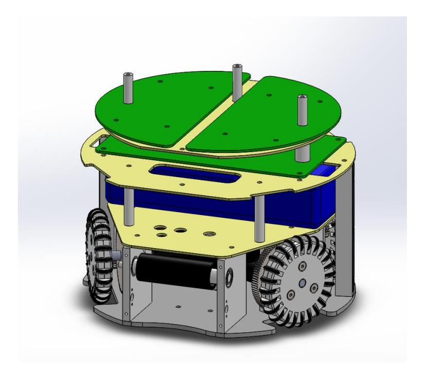
The mechanical structure is the same of the last year, accommodating the locomotion system with its four Faulhaber 2342 DC motors, the kicking device, and the dribble device mounted with shock absorber system and linked to another Faulhaber 2342 DC motor. The upper part houses the three electronic boards, the battery and the kick capacitor using glass fiber plates; and the cover is a front cut cylinder with protected wheels and openings for the kicking and dribble devices. All mechanical structure is made of aluminum and composite materials as shown in figure 1.
3 Electronic Devices
The electronic devices are the same of last year, composed of three electronic devices: MainBoard, MotorBoard and KickBoard and detailed information can be found in [1] [2]. The main improvement was in the PID, which were continuous, changed to discrete and later applying N filter in discrete PID, improving the performance of the controller.
The initial implemented controller was a Continuous PID, which, according to the Digital Controller [5], was inconsistent since we're dealing with a microcontroller system (robot). After identifying this situation was proposed the implementation of a Discrete PID.
– Continuous PID - The previous controller implemented in the robots used the following equations:
$$u(t) = K_p e(t) + K_i \int_0^t e(\tau) d\tau + K_d \frac{de(t)}{dt}$$
$$e(t) = SetPoint - PlantOutput : Error$$
- Discrete PID The first controller proposed to adequate the control system was a Discrete PID Controller. In the discrete domain, the operation of the controller is not continuous, since its actuation is periodized by a certain interval T⁰ (sampling time) [5]. The equations used in this controller are presented below [13]:
- Controller Transfer Function The proposed controller has the following relations between its calibration constants and its zeros location. The equation below showing the model in the discrete time that represents the controller.
$$G_{PID}(z) = q_0 \frac{(z - z_{01})(z - z_{02})}{z^2 - z}$$
$$z_{01} + z_{02} = \frac{-q_1}{q_0} \qquad z_{01} z_{02} = \frac{q_2}{q_0}$$
- Calibration Process Next, it's presented the calibration processes used for determining the controller coefficients:
- First, it's necessary to guess an initial value of the maximum speed of the motor over load. The motor's datasheet informs that the maximum motor speed is 8100 RPM. Then, a speed on load of 7000 RPM was assumed.
- Next, the value of the coefficient q⁰ was defined by analyzing the controller's behavior for u(k = 0). In addition, we studied the worst cases of controller output (±12V ) and error Speedmax.
$$u(0) = Voltage_{Max} = 12V$$
$$e(0) = Speed_{Max} = 733.04rad/s$$
$$q_0 = \frac{u(0)}{e(0)} = \frac{12}{733.04} = 0.016370222718024$$
- 3. The discrete model of the motor plant was defined:
$$G = \frac{0.0435}{4.14e^{-10}s^2 + 2.106e^{-5}s + 0.00192}$$
The discrete counter-part with a sampling time of 0.001 seconds is described by:
$$Z = \frac{1.94z + 0.03726}{z^2 - 0.9127z}$$
- 4. The MatLab RLTOOL tool was used to optimize the coefficients of the discrete controller of the discrete plant of the Motor. But first, it's necessary to find the zeros location.
$$G_{PID}(z) = q_0 \frac{(z - z_{01})(z - z_{02})}{z^2 - z}$$
Obtained values:
$$z_{01} = 0.823840 \qquad z_{02} = -0.030368$$
- 5. Found the positions of the real zeros, it's possible to obtain the values of the coefficients q¹ e q² of discrete controller by the following equations:
$$z_{01} + z_{02} = \frac{-q_1}{q_0} \qquad z_{01} z_{02} = \frac{q_2}{q_0}$$
Isolating the coefficients:
$$q_1 = -q_0(z_{01} + z_{02}) = -0.012989313360516$$
$$q_2 = q_0 z_{01} z_{02} = -4.095563400170131e^{-04}$$
• Controller Equation - Found the calibration coefficients through MatLab RLTOOL tool, the next step were to implement the following equation in the microcontroller:
$$u(k) = u(k-1) + q_0 e(k) + q_1 e(k-1) + q_2 e(k-2)$$
$$q_0 = K \left( 1 + \frac{T_D}{T_0} \right)$$
$$q_1 = -K \left( 1 + 2\frac{T_D}{T_0} - \frac{T_0}{T_i} \right)$$
$$q_2 = K\frac{T_D}{T_0}$$
Where The parameters T0, Tⁱ , and Tᵈ denote the time constants of the proportional, integral, and derivative terms respectively, and K the proportional gain.
– Discrete PID with N filter - In many PID controllers, the constant N is added to the derivative term, which acts as a low pass filter and attenuates high frequency noise components (f >N), which would cause a high unwanted derivative gain (derivative has zero at 0).
$$K_d = K_d s \left(\frac{N}{s+N}\right)$$
In real applications, the controller's output signal can be very noisy, for this reason it's quite common to utilize the derivative term with a N filter constant. Thus, it also was studied this second discrete PID approach [5].
• Controller Transfer Function - Discretizing the derivative term using the Backward Euler method, we have that the controller's transfer functions is [5] [13]:
$$C(z) = K_p + \frac{K_i T_s z}{z - 1} + \frac{K_d N(z - 1)}{(1 + NT_s)z - 1}$$
• Controller Equation - Since our final objective is to implement in a microcontroller, we need to change the representation of the transfer function of a different equation representation, as presented below.
$$C(z) = \frac{U(z)}{E(z)} = \frac{b_0 + b_1 z^{-1} + b_2 z^{-2}}{a_0 + a_1 z^{-1} + a_2 z^{-2}}$$
$$b_0 = K_p(1 + NT_s) + K_i T_s(1 + NT_s) + K_d N \qquad b_1 = -(K_p(2 + NT_s) + K_i T_s + 2K_d N)$$
Rearranging the terms,
$$a_0U(z) + a_1z^{-1}U(z) + a_2z^{-2}U(z) = b_0E(z) + b_1z^{-1}E(z) + b_2z^{-2}E(z)$$
b² = Kᵖ + KdN a⁰ = (1 + NTs) a¹ = −(2 + NTs) a² = 1
$$u[k] = -\frac{a_1}{a_0}u[k-1] - \frac{a_2}{a_0}u[k-2] + \frac{b_0}{a_0}e[k] + \frac{b_1}{a_0}e[k-1] + \frac{b_2}{a_0}e[k-2]$$
Where the constants depend on Kp, Kd, Ki, N and Ts. We also used the RLTOOL for obtaining the optimized controller of the motor. Next, we calculate the coefficients for the above equation and implement the discrete controller with N filter.
$$u(k) = 1.6931u(k-1) - 0.6931u(k-2) + 0.0209e(k) - 0.0291e(k-1) + 0.0099e(k-2)$$
4 Computer Systems
The WR Magic Project software is now based on five sub-projects developed by the group: the GEARSystem library, the WRBackbone server application, the redesigned WRCoach strategy application, the newest WREye vision filtering application, and the newest WRStation radio communication application.
4.1 GEARSystem
The GEARSystem, same used the last years, is a distributed system library that provides communication between all system modules [9]. It is built over CORBA and allows a distributed execution of the modules.
The library architecture is minimalist, with four basic elements: Server, Sensor, Controller and Actuator. The sensors can create teams, players and balls and set their information (position, orientation, velocity, etc). Controllers may read these information and send commands to the actuators (move, kick, dribble, etc). Actuators read, decode these commands and execute them. The Server connect all those elements. This architecture allows the easy development of new software based on the four main modules, and detailed information can be found in [1] [2].
4.2 WRBackbone
The backbone is the Server module on the GEARSystem architecture. It doesn't have any significant function other than acting as the server that connects all modules.
4.3 WRCoach
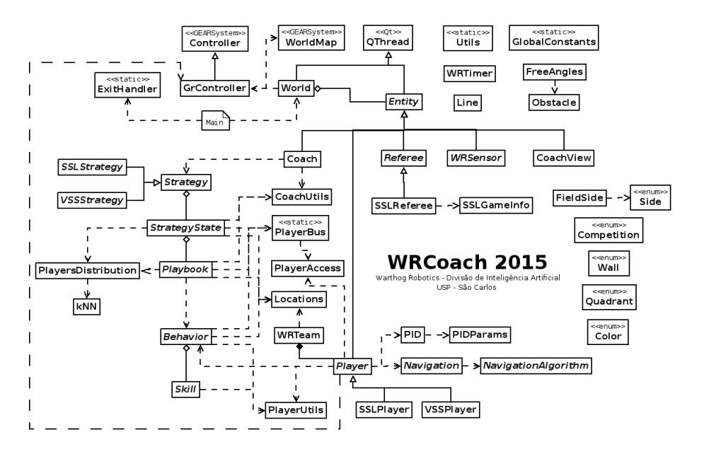
The coach is the Controller module on the GEARSystem architecture and is responsible for setting the strategy to the team. A simplified snippet of the software architecture is presented in figure 2. The subsequent paragraphs describe the Coach architecture; a full description of the software is available in [2] and in Brazilian Portuguese at [10].
4.4 WREye
The eye is the Sensor module on the GEARSystem architecture and is responsible for receiving the data from ssl-vision software, filtering the data, and inserting it on the system.
It is basically composed by the Kalman, Noise, Loss and Multi Object filter, a more detailed explanation of it can be found in [2].
4.5 WRStation
The station is the Actuator module on the GEARSystem architecture and is responsible for sending the commands generated by WRCoach to the robots. It essentially connects via USB using QtSerialPort [11] to a custom station board that reproduces the commands wireless.
5 Improvements for 2017
The mechanical and electronic projects are the same from 2015, the main improvement for 2017 will be in the embedded software in telemetry system. This improvement is aimed at taking a lot of data that allow make a more faithful rigid body system, to have a model of robot more real as possible and increase the quantity of controllers applied in the robot.
The new three-tier control model for the robot still under development with one controller of the robot's velocity, one motor speeds and high-level one for the AI modules.
The presented WRCoach structure is completely new and allows more control over the AI components, facilitating the coding execution.
6 Conclusion and Future Work
In computer system, the improvement of the coach described in [2] was a great change in the strategy of the WRCoach and turn it more complex. Having that in mind, the improvements in the year of 2016 were focused on the optimization of the current code, making the algorithm more stable and efficient.
The developed hardware is robust, reliable and provides an excellent platform to the strategy systems, and the improvements were focused in the embedded software as show in this paper, like the controller of the robot.
Future works will be focused mainly in those areas, improving the software WR-Coach and the embedded software of the robot like the controller.
7 Acknowledgments
The authors would like to thank all Warthog Robotics team for the help and friendship; the University of São Paulo for the facilities and financial support; the Griffus, Embraer, Caster, Infox companies for the technical sponsorship; and all others that helped us during the project.
References
- Lang, R.G., Bernardo, A.M., Oliveira, G.C., Menezes, H.B.B., Ramos, L.C., Roque, L.G.S., Silva, I.N., Romero, R.A.F.: Description of the Warthog Robotics 2015 project. In: 2015 RoboCup (2015)
- Lang, R.G., Oliveira, G.C., Menezes, H.B.B., Rosa, N.S., Correa, R.A., Gomes, V.H., Silva, I.N., Romero, R.A.F.: Description of the Warthog Robotics 2015 project. In: 2016 RoboCup (2016)
- Nordic Semiconductor: High Frequency 2.4 GHZ Wireless Transnciever. Data Sheet (2007)
- Olivera, V.A., Aguiar, M.L., Vargas, J.B.: Sistemas de Controle Aulas de Laborat´orio. EESC-USP, Brasil. (2005)
- Aguiar, M.L.: SEL359 Controle Digital,2015. EESC-USP, Brasil. (2015)
- Pressman, A.I.: Switching Power Supply Design. McGraw-Hill. (2003)
- Mohan, N., Undeland, T.M., Robbins, W.P.: Power Electronics Convertes Application and Design. Wiley (2002)
- Tse, C.K.: Complex Behavior of Switching Power Converter. CRC Press. (2003)
- Lang, R.G., Romero, R.A.F., Silva, I.N.: Development of a Distributed Control System Architecture. In: 2014 Latin American Robotics Symposium. (2014)
- WRCoach v2 documentation. Division of Artificial Intelligence Warthog Robotics, available at https://www.assembla.com/spaces/warthog-dia/wiki/WRCoach\_v2.
- Qt Company: QSerialPort documentation, available at http://doc.qt.io/qt-5/ qtserialport-index.html.
- Wikipedia: PID Controller, available at https://en.wikipedia.org/wiki/PID\_ controller.
- Control System Labs: Discrete-time PID Controller Implementation, available at http://controlsystemslab.com/ discrete-time-pid-controller-implementation/