ZJUNlict Extended Team Description Paper for RoboCup 2017
Tianyao Gao, Yanan Wu, Tong Yang, Zheyuan Huang, Rong Xiong
National Laboratory of Industrial Control Technology, Zhejiang University, Zheda Road No.38, Hangzhou, Zhejiang Province, P.R.China
http://www.nlict.zju.edu.cn/ssl/WelcomePage.html
Abstract ZJUNlict has been participating in Robocup for about ten years since 2004. In this paper, we summarizes the details of ZJUNlict soccer robot system we have developed in recent years. we emphasize on the creative ideas of designing the robots hardware and our software systems. Also, we will share our tips on some special problems.
1 Introduction
Our team is an open project supported by the National Lab. of Industrial Control Technology in Zhejiang University, China. We have started since 2003 and participated in RoboCup during 2004-2016. The competition and communication in RoboCup games benefit us a lot. In 2007-2008 RoboCup, we were one of the top four teams in the league. We also won the first place in Robocup China Open in 2006-2008 and 2011. We won the first prize in 2013 and 2014, which is a great inspiration to us. Also, we incorporate what we have done in recent years in this paper.
Our team members come from several different colleges, so each member can contribute more to our project and do more efficient work. Our team members are all ungraduated in our university. We are trying to update our robot system from hardware to software using knowledge we learned from school and other team's paper.
2 Hardware
2.1 Mechanical Improvements
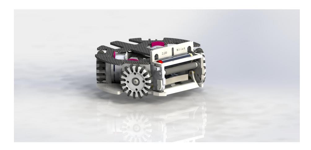
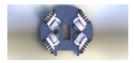
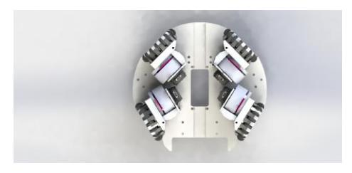
- I A reconfiguration of the baseplate. We switched the encoders with 360 cycles per revolution. This switch will not influence our control of the motors. This contributed to a considerable decrease of the volume . Meanwhile, the angles of the wheels are more appropriately arranged. As for the previous type of the baseplate, the interspace was not enough because of the encoders with 512 cycles per revolution. Therefore, we had to move the four wheels forward and backward for a short distance. However, after changing the encoder, we can remove this useless distance.
- II An expansion of the width of the mouth. During the former competitions, the pass-taking performances of our robots were not so satisfactory. An obvious reason is the width of the mouth is too small——the previous width of the mouth is only 60mm. After the modifications of the baseplate, the width of the mouth has been expanded to 74mm or even wider. As a result, we can take and pass the ball more stably. As it shown in Figure 2, the structure is previous baseplate and wheels and the structure in the Figure 3 is new baseplate and wheels.
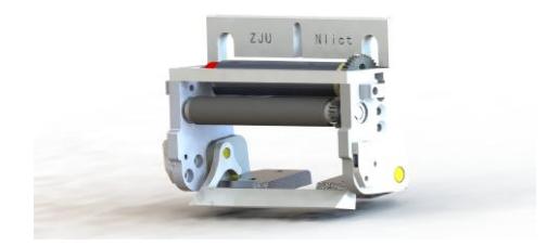
- III We think that the coverage-ratio of the ball has a great influence on the capabilities of stopping, gripping and chipping the ball. In order to further improve the performance of the robot, we calculated the relationship between the height of the grip rod and the coverage-ratio. In the previous structure, the height of the control club is only 28mm relative to the upper side of the baseplate. And the maximum coverage-ratio with non-grip state under the actual measurement is only about 12%. In this years design, we increase the grip rod by 2mm, and the maximum coverage-ratio is now about 15% with non- grip state and up to 18% with grip state. Therefore, our robots have significantly improved the ability to take a pass and the stability of the gripping and chipping.
2.2 Electronic Improvement
(1) System Transplantation
With the increasing of the complicacy of our moving system, it becomes more and more significant for us to search for a new approach to simplify the process of adding up new algorithms. This year, as a team which is formed purely by undergraduate students, we decided to move our embedded system from the FPGA to STM32 in order to decrease the difficulties in learning for our new team members who are usually sophomores. To complete it successfully, following steps are of importance to be taken:
I Remove five BLDC motor drive systems from FPGA
Last year, we have successfully separated the BLDC motor drive system using five independent STM32. However, we thought it too difficult to make additional improvement since the BLDC motor drive depends hugely on the reacting time of STM32 which only have a system clock of 72MHz.It means the driving code has been pretty precise to make sure its efficiency. As a specific chip of motor driving, one named A4931 is our primary choice. However, the footprint (QFN28) is so difficult for those students who have not received professional directions on soldering. Thus, instead of worrying about the quality of our board, a demo with brushless DC motor controller MC33035, containing a footprint of SO-24 or PDIP-24, and its reference design schematic diagram which lies in the datasheet of MC33039 has been designed .
II Change the Verilog code
In our previous verilog code, the part of driving and the part of making decision have correlated with each other so inseparably that hardly can we reserve the one with the absence of the other one. Hence, we also rewrite all the communication protocol code in another independent STM32 then the whole system will consist of 6 STM32. Until recently we have not designed a test board of communication module and we will continue doing it.
(2) Chip Kick Improvement
From the previous experience of our competition, there is also a serious problem in the robots performance in flip shot which is so weakened compared with our grazing shot. Subjected to the mechanical conditions, the depth of the ball caught by the mouth of the robot cannot keep constant which leads to the difficulty in keeping the precision of flip shot. However, at least we can increase the distance of flip shot by strengthen our power board. A major idea is to add the voltage of the capacitor from 190V to 250V. There are also several steps towards this destination.
I Appropriate MOSFET and rectifier
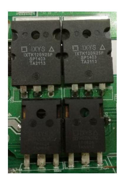
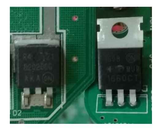
In the past three years, we have been keen on the usage of UC3843P in the power board which divides the controlling system of the capacitor and the large voltage circuit totally, which enables us to increase the voltage without much efforts since the controlling circuit is still suitable for the new board. Eventually, we change the MOSFET from IRFR15N20D to IXFH52N30Q together with the replacement of ultrafast rectifier from MURD620 to MUR1640CTG.
II Specific Capacitor
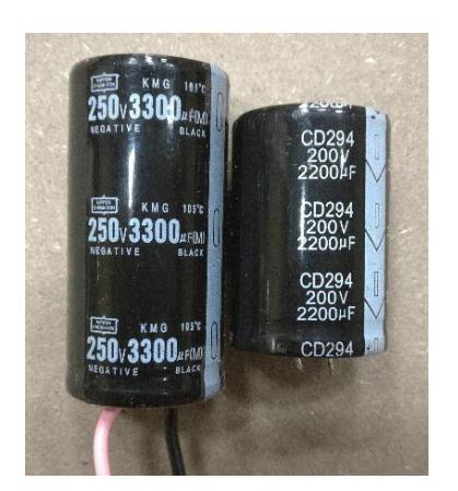
The capacitor we previously used was 2200uF and had a maximal voltage of 200V. When it comes to the new board, changing the capacitor has been an inevitable step for our success. The stronger the capacitor will perform, the huger its appearance will be. It was a vital problem to prevent our capacitor from being over-sized, especially its height. Through contact with a factory in Hangzhou, we now own a new one with the characters as below:
Until February we have designed a board which can withstand a voltage of 300V and shoot the ball without explosion because of the overloading current of PCB board. This improvement lengthened the flip shot distance by half, from 4m to 6m. We will continue to change the shape of the board and adjust the gesture of the capacitor in order to fit in our previous robots. We hope there will be a robot showing up in the competition with a stronger body.

3 Software
3.1 Restore the Trajectory of Flip Shot
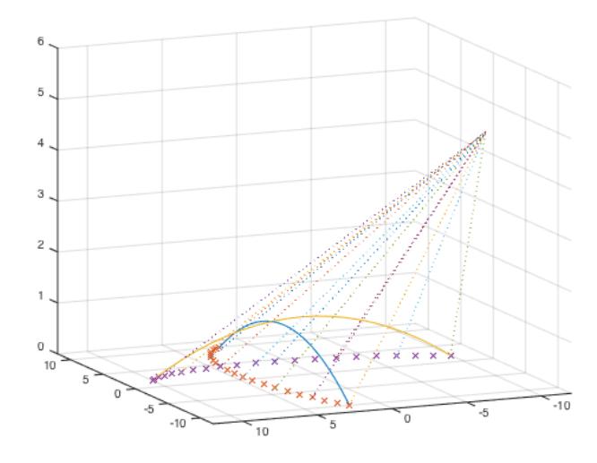
At the time of flip shot, the image inside the camera is presented by arc, which is caused by the height of the ball which influences the camera showing projection. So we can restore the projection and predict the trajectory through restoring camera height and location.
We place a ball at each site of four corners, and gain their position A1 from the image. Then we put the ball on a known project, whose color doesnt interfere, and read their position A2 as well. Every four sets of data can restore a cameras height and position, which is feasible after tests.
After we knew the height of cameras, we can execute the following steps to restore the actual trajectory of balls (assuming the acceleration of the ball in the air is exactly the gravity acceleration)
- Decide the benchmark line using the direction of the robot the last time it contacted the ball.
- Generating all the attack routes and defend routes.
- Decide the benchmark line using the direction of the robot the last time it contacted the ball.
- Through restoring the points in the air to the benchmark line, we adjust the benchmark line on dichotomy, until the velocity of points approaching to be constant.
- Restore the height of ball at every frame, and the intersection of parabolic and the ground is supposed to be the first drop point.
3.2 Predict the Collision of the Ball
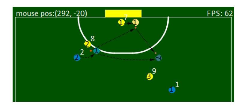
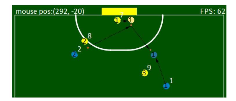
When the ball is fast enough and tends to collide with robots, it is very important to predict the direction of ball's velocity after the collision. We can predict the movement of the robot and the ball to predict the collision point. And with the physical models, which may occur at the collision point we can predict the direction and velocity of the ball. This could be efficient for the movement of robots.
It is mainly divided into the following steps:
- With the motion model of robots we can decide whether the ball will collide into enemy robots or not (under the condition of the ball having huge velocity).
- Estimate the 3D model of enemy robots to decide the direction and velocity of the ball, and calculate the intercepting point.
- Calculate the best player to run to destination(using path planner like RRT to consider which robot will be the first one to arrive destination).
Through the tests, the prediction of the ball destination is better for task match, but the prediction of the velocity is affected by many factors, we just use the same velocity we predict that the ball has collision with robot.
3.3 Velocity Control
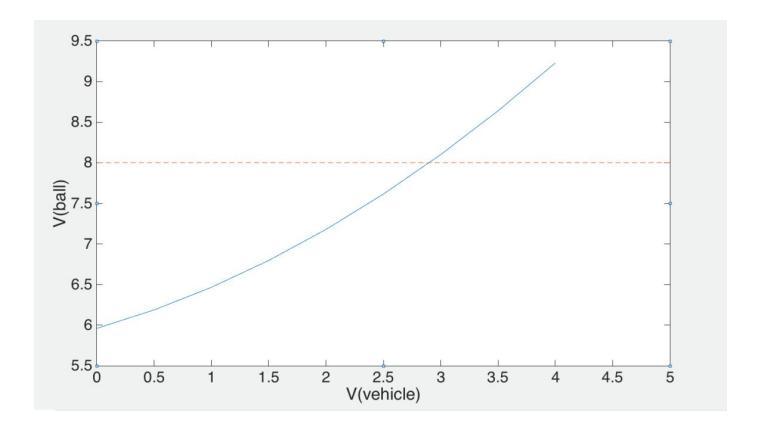
In RoboCup 2016, overspeed has been penalized for many times. This is because the impulse brought by the velocity of the robot and the discharge which drives the shovel is acted on the ball. We used the max speed of ball (last year in Leipzig is 850 cm/s) subtract the current component of the velocity of robot in the ball speed direction to set the flat kicking power for the robot. But in fact the effect of robot component speed and ball speed is not linear. We use a two-dimensional table to fix this problem, the speed of robot component in ball speed direction V(robot-component), assuming that speed of ball doesn't make a greater influence than speed of robot.
We measured the influence on the ball from the velocity of the robot through tests when the ball is still. The figure above shows robot kicking the ball with power 600cm/s when robot and ball are both still. And when the robot has initial speed, the effort of ball speed is less than linear plus of robot and ball speed. And from the tests we find that the two-dimensional table is different when using different mechanical construction.
3.4 Vision Processing Module
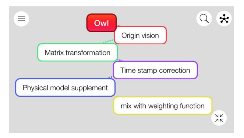
Images is a extremely crucial part in the competition. As the input of the whole progress, the degree of excavation of image information determines the degree of control of the game. So we rewrite the vision module this year. It includes two parts, one is processing the data from ssl-vision software and the other is processing the data about ball and robot including the prediction. The prediction includes two parts, the first one is predicting when vision loses and the second is predicting the action for opponents according to vision. The second one tends to execute in strategy part, so we won't discuss with it in this section.
Matrix Transformation In the ssl-vision software, there's an part to do the adjustment and correction of the site's distortion. However, in the actual game it will often appears that the field vision is not perfect splicing. This situation will make the image of the same robot appears a quite long distance in two images. So we will base on the principle of least squares method to measure a flattened-correction matrix for the field.
Time Stamp Correction In the ssl-vision software, each field is collected and identified by its own camera. This complete-separate solution will result in the time inconsistency after we merged our data of four field directly, which will make the image information have a slight deviation. So we decided to correct the relatively early image information according to the packet acquisition time of the data, and thus we can stitch all the four field's image and receive an perfect whole image. Mining data in time-corrected images makes it easy to obtain more accurate smooth velocity variations.
Correction of physical model Although the camera of the field uses a topdown way to collect images, it is in a small piece of the center of the site, thus:
- When the robot deviates from the camera with the ball in the front, the camera can not get the data of the ball.
- When the situation of multi-robot race appears, it is prone for the camera not to collect the data.
- Because the acquisition of the color has a certain degree of instability, when there is a slight image disturbance, the loss of the robot situation tends to happen.
- Because the acquisition of the color has a certain degree of instability, when there is a slight image disturbance, the loss of the robot situation tends to happen.
According to the above cases, we will simulate each sub-field in the physical engine to compensate the loss of data.
At the same time, we found that when the ball is at a certain height (when picking the ball),the projection in the single field becomes into a smooth curve. In the cross-field, the original basically coincide with the location will be clearly separated, this type of data is very conducive to our adjustment of the height of the ball.
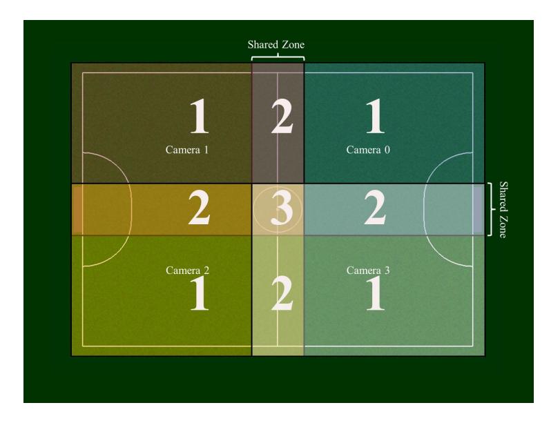
Fusion Data When we have finished the previous steps, the image of a single sub-field is stabilized. We need integrate the images of multiple fields into the final image of the current frame. The problem appears only when the junction of the fields. When a robot appears in two sub-fields at the same time, the data processing will be needed.
The areas in the filed are divided into three parts
- once detected
- twice detected
- four-times detected
The expression of ball position are shown respectively:
- symbols description:
- In zone 2, d stands for the vertical width of the strip domain
- In zone 2, d k (k can be a,b,c or d) stands for the vertical length from area k to the ball
- In zone 3, c k (k can be a,b,c or d) stands for the diagonal length from the angle of area k to the ball
- zone 1: ball.pos = ball.pos a
- zone 2: ball.pos = [ball.pos a * (d - d a) + ball.pos b * d a]/d
- zone 3: ball.pos = [ball.pos a * (1.414d - c a) + ball.pos b * (1.414d - c b) + ball.pos c * (1.414d - c c) + ball.pos d * (1.414d - c d)]/[5.657d- (d a+d b+d c+d d)]
References
- Brett Browning, James Bruce, Michael Bowling and Manuela Veloso, STP: Skills, tactics and plays for multi-robot control in adversarial environments
- STOX 2015 Extended Team Description: http://wiki.robocup.org/File:Small Size League - RoboCup 2015 - ETDP STOx%E2%80%99s.pdf
- STOX 2016 Extended Team Description: http://wiki.robocup.org/File:Small Size League - RoboCup 2016 - TDP STOx%27s.pdf
- CMDragon 2016 Extended Team Description: http://wiki.robocup.org/File:Small Size League - RoboCup 2016 - TDP CMDragons.pdf
- Yonghai Wu, Penghui Yin and Rong Xiong, ZJUNlict Team Description Paper for RoboCup2011
- Yonghai Wu, Xingzhong Qiu, Guo Yu, Jianjun Chen and Xuqing Rie: Extended TDP of ZjuNlict 2009
- Poudeh A G, Esmaeelpourfard S, Hosseinikia A, et al. MRL extended team description 2014
- Mendoza J P, Biswas J, Cooksey P, et al. Selectively Reactive Coordination for a Team of Robot Soccer Champions[C]//AAAI. 2016: 3354-3360.
- Perun B, Knig C. Design and Implementation of a realtime pathplaning module for holonomic Robocup Small Size League robots in JAVA
- Baker B R, Reynolds M, Liu W. Strategy specification for teamwork in robot soccer[C]//Proceedings of the 2006 international symposium on Practical cognitive agents and robots.ACM, 2006: 129-140.