AIS Team Description Paper
Tomás Rodenas, Ricardo Alfaro, Pablo Reyes, Diego Pandolfa, Felipe Pinto, Maximiliano Aubel, Pablo Yanes, Tania Barrera, Sung Hee Kim, Sebastián Castillo
Universidad Técnica Federico Santa María, Valparaíso, Chile; Innovación y Robótica Estudiantil UTFSM
Abstract This paper describes the current development status of our SSL team, AIS, with the purpose to qualify for RoboCup 2018. Throughout this document, we present the design and implementation we have got so far in order to meet the requirements involved in the classification step for Division B, showing the electrical, mechanical and software topics involved in our work, which were designed according to satisfy the RoboCup rules.
1 Introduction
Innovación y Robótica Estudiantil, which is the affiliation of all members on this team, has been founded in 2001 and corresponds to a self-organized group of undergraduate and graduate students from several faculties, such as Electronics, Informatics and Mechanical Engineering Departaments at the University (UTFSM). This RoboCup team belongs to one of several projects from this aggroupation, and is conformed by students with different specialization areas such as computer science, control and automation, or power electronics, but also on a multidisciplinary approach including students from mechanical engineering, as well as industrial engineering students.
This SSL team follows the nature of the host students initiative, starting from its multidisciplinary constitution, the self-organization and motivation with professor advises when required but managed independently from any professor funding project, and trascendence over generations renewing its members with a constantly growing development and enhancement, and making both research and development works, like [1] where a previous generation of the team applied reinforcement learning on the goalkeeper task.
This document describes our design and the implementation we have got so far, showing all the work made in the different areas involved at this category.
In particular, we describe mechanical design, electronics design for different devices and algorithms implementation for the (robotics) team coordination, also including the expected implementation we are planning to reach by the time of the competition.
2 Mechanical Design
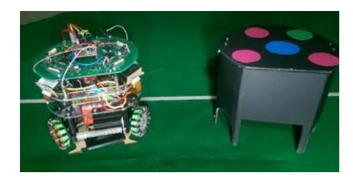
The current model corresponds to the third version of the robot designed by our team throughout the last generations of members. The design was recently updated changing the mechanical structure, with an special emphasis on the dribbler development and wheels design.
The material selected for the chassis structure is chosen by means of priorizing the collision resistance, so an aluminum base is used, while supports for the wheel motors also consists on four aluminum blocks and a second floor of polymethylmethacrylate (PMMA) which stands for supporting the battery. Then, a third floor is designed also of PMMA, with the aim of supporting the PCB and also isolating the battery and PCB. Finally, the cover is 3D-printed on ABS material.
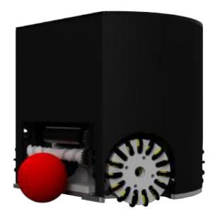
-Height: 150 mm. -Diameter: 180 mm.
-Maximum coverage of the ball: 18%.
2.1 Drive System
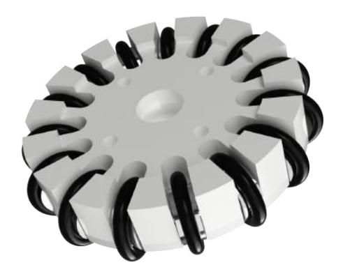
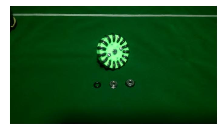
Mechanical locomotion of robots is based on 4 omnidirectional wheels, which are currently 3D-printed in PLA but we plan to switch to ROBALON which is a thermoplastic that has to be milled on a CNC router (we also plan to change the wheels support block material from aluminum to ROBALON). This change of material is expected to benefit from its very high wear resistance, very high impact strength, low density and virtually no moisture absorption. Each wheel is designed with 55 mm of diameter and 15 sub-wheels of 13.5 mm of diameter, so the robot can move in all directions. Also, each one of the 55 mm diameter wheel has a set of 15 mini metal V grove guide pulley rail ball bearing wheels. Each wheel is driven by a Maxon EC45 30 Watts motor [5] and a L6235 driver for 3-phase brush-less DC motor [4], which enables us to program a velocity control for each motor, ensuring that the robot moves to our desired setpoint speed.
Figure 3 and 4 shows the described wheel.
3 Hardware
Each robot is controlled by a PIC MX440F256H using Pinguino Development board. This model was chosen because of its simplicity, versatility and peripherals features. It has shown an acceptable performance letting us accomplish communication, movement and playing skills. The peripherals also replace a lot of external electronics needed to control the motors and dribbler.
3.1 Peripherals
ADC conversion The ease of implementation of this kind of modules allows us to control wheel speed and orientation through a L6235 driver using DAC conversion. Additionally using ADC conversion we can measure the wheel speed, allowing us to implement a PID control on velocities for each wheel.
I $^2$C As mentioned before, we use a L6235 driver, which communicates with the PIC through its I2C module.
UART The UART module allow us to develop serial communication between the PIC and our APC220 RF module, which will send and receive data from the centralized decision maker placed on the computer. Additionally we use an FTDI connected to our UART communication module to watch data of interest.
GPIO The general purpose Input/Output pins let us to program easily in general any other significant settings, i.e. set the wheel break and direction pins or activate the kick routine.
3.2 Kicker
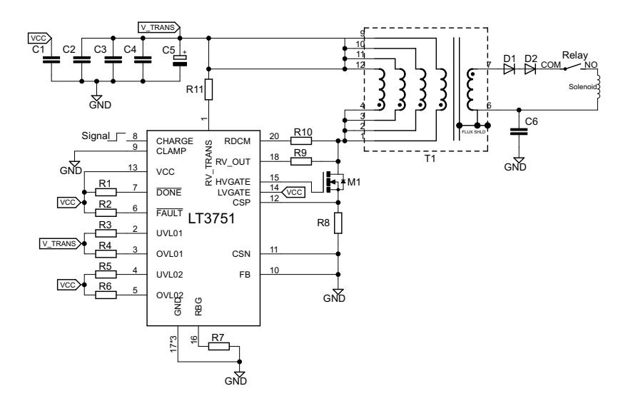
The circuit shown in Figure 5 is used for the kicking system. This consists of a chip charger controller with regulation which is a controller of flyback of high voltage, raising the voltage from 24 [V] to 100 [V] on a capacitor of 2400uF and, therefore, storing an energy of 244 [J]. The time of charge of the capacitor takes up to 3 seconds to reach the voltage setpoint and can be regulated to kick with different intensities.
3.3 Dribbler
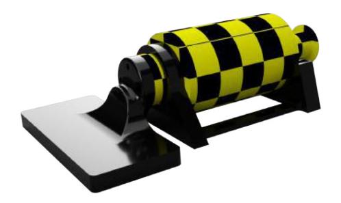
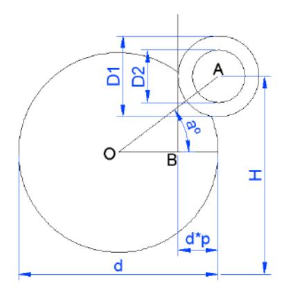
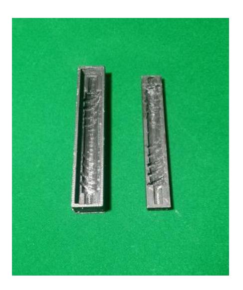
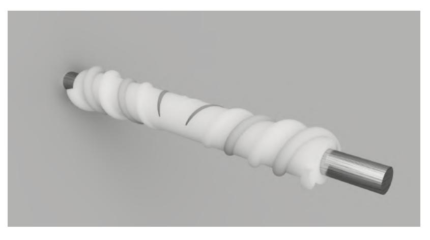
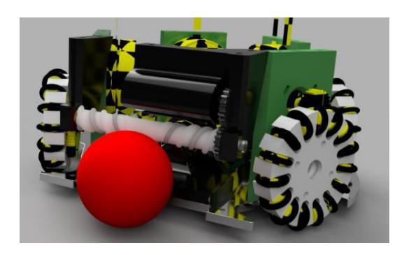
According to RoboCup rules, the robot is allowed to cover up to 20% of the ball. Experimentally, it has been proved that it is easier to catch the ball when the dribbler has a slightly curve to center the ball on its own. So, this design involves two diameters, D1 and D2 and based on this information, maximum height possible is calculated obtaining the following expression:
$$H = \sqrt{\frac{1}{4}(D_2(2d+D_2) + D_1(4pd-2d-D_1) + 4pd^2(1-p))} + \frac{d}{2},$$
(4)
where d and p corresponds to the ball diameter and maximum coverage of the ball, whose relation is illustrated in Figure 7.
4 Communication
For communication we use an RF module consisting of an APC220 which is a low cost NRF Athena that integrates an embedded high speed microprocessor and high performance IC that creates a transparent UART/TTL interface. It is a 430 MHz system capable of transmit up to 1000m.
We send every single robot data through a common channel as hexadecimal packages in order to achieve a better transmission bytes. Each robot receives and decodes the data in a pic microcontroller.
5 Kinematic model and wheel speed control
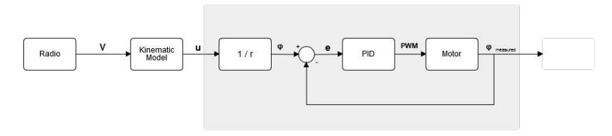
In order to maintain the expected velocity and position, we applied PID control on every wheel once the setpoint speed is calculated for every robot. To accomplish this task, our control system sends a velocity vector V = [vx, vy, vθ] T to each robot, multiplying then its kinematic model matrix W, defined by the geometry of the robots, obtaining
$$u = V^T W = [u_1, u_2, u_3, u_4]^T = \phi r,$$
where u is the wheel velocity vector, which divided by r (radius of the wheel), it is possible to obtain the angular velocities of the wheels, φ. This is the reference variable to the control speed system shown in Figure 11, and by obtaining direct measure from the hall sensors of the motor we can obtain the input error variable to the PID. Then, the controller generates a PWM as output in order to set the wheel speed. It is important to note that φ is treated as an absolute value, because the direction is set by enabling or disabling certain pins on the driver controller.
6 Software
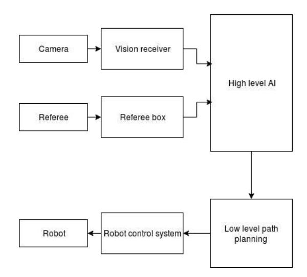
Diagram depicted in Figure 12 shows a general overview of the system, where we implement a high level AI decision making in order to decide which is the best action to take from a set of preprogrammed plays based on the game state that comes just from the vision receiver.
Then we have a low level path planning algorithm to choose the best path in order to execute the play avoiding obstacles. This is implemented on the desktop computer in charge of making the centralized decisions for every robot.
6.1 High level AI
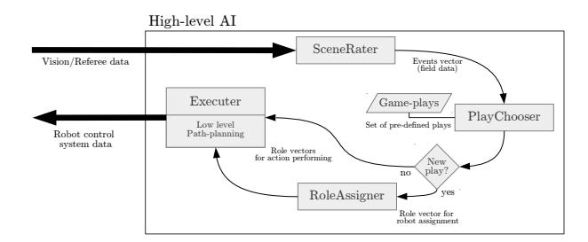
The higher order AI level computes at each processing cycle the best actions to be performed for each robot. This action is chosen by selecting a game-play from a pre-defined static pool. This fundamental part of the system's architecture is shown in Figure 13, introducing four identifiable processes. First there is a SceneRater which analyse and encapsulates all the relevant information from the game field for choosing a game-play. Then, that information is used for actually selecting the specific game-play through the block named as PlayChooser, weighting each detected event for deciding whether an attacking strategy or a defensive one should be used, and which one in detail must be performed. Once a game-play is chosen, then a RoleAssigner block is in charge of coherently distribute the roles associated to that game-play, as well as selecting which robots should assume each position. Finally, each position must be run by the robots, process managed through time by a Executer block.
6.2 Low level path planning
Under the high level plays we run a path planning algorithm to find the best way of executing these tasks. We have tested different methods looking for a suitable algorithm which gives good results at the moment of avoiding obstacles.
The first method tested was Potential Field algorithms [3]. This proposes a potential field representation for obstacles and target, using sources for the prior and sink for the latter. In this way, vector trajectories are generated avoiding obstacles and leading the agent to the target, as we let a ball fall down. A disadvantage of this method, is that we could obtain local minimums without reaching the target.
Based on this approach we found the "Ameliorative APF Algorithm" [7]. This method has a threat coefficient, defined as $e_{or}$ , determined by synthesizing the effect of the relative position and velocity among the robot, the obstacle and the goal (it takes values from 0 to 1). Also we define the maximum and minimum threat range given by $(D_{threat}){max}$ and $(D{threat})_{min}$ . Then the relative position of the obstacle and the robot is described by parameter $(\alpha+\beta)$ , while $\gamma$ gives the direction angle of the obstacle relative to the robot $(\gamma \in [0, \frac{\pi}{2}]$ means that the robot is going to collide). The following pseudo code gives the robot's velocity $vecv_r$ .
Algorithm 1 Ameliorative APF Algorithm
1: loop:
 2: if D_{ro} > (D_{threat})_{min} then
 3:
         if D_{ro} \leq (D_{threat})_{min} then
 4:
              if v_{or} \neq 0 then
 5:
                   if (\alpha + \beta) \in [-\frac{\pi}{2}, \frac{\pi}{2}] then
 6:
                        if (\alpha + \beta) \in [-\frac{\pi}{2}, 0) \uplus (0, \frac{\pi}{2}] then
 7:
                             if \gamma \in [0, \frac{\pi}{2}) then
 8:
                                 get e_{or}
 9:
                             else
                                  goto bottom.
10:
11:
                        else
12:
                             goto bottom.
13:
                   else
14:
                        goto bottom.
15:
               else
                   goto bottom.
16:
17:
          else
18:
               bottom:
19:
               e_{or} = 0
               get v_r
20:
21: else
          CRASH BACK
22:
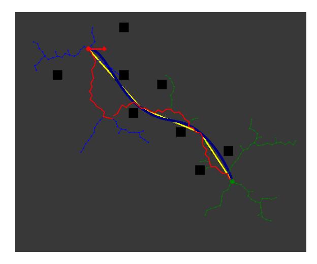
The second method tested was Rapidly Exploring Random Trees (RRTs), which is shown in Algorithm 2 and consists on expanding a tree on the target zone, avoiding to add nodes that could produce collisions with targets. The added points to the tree are randomly chosen with probability p in a straight line to the target, and with probability (1-p) selecting a random point on the space, making more exploration and avoiding to get stucked on a different location to the target, as shown in Algorithm 3.
Algorithm 2 Rapidly Exploring Random Trees
1: procedure BUILD-RTT(xinit)
2: T.init
3: for k = 0 to K do
4: xrand ← RandomState()
5: EXTEND(T, xrand)
     return T
Algorithm 3 procedure involved on RRT
1: procedure EXTEND(T,x)
2: xnear ← NEAREST-NEIGHTBOR()
3: if NEW-STATE(x, xnear, xnew, unew) then
4: T.add-vertex(xnew)
5: T.add-edge(xnear, xnew, unew)
6: if xnew = x then return Reached
7: else return Advanced
     return T rapped
For improving its performance, we have implemented and tested some of the algorithms based on RRT, way-points, smoothing and some extensions like RRT* presented on 2011 [2].
7 Expected Capabilities
By the time of the competition we expect to have built at least four robots, if there were not any more electrical failures in hardware we would expect to have built five robots, and have improved some aspects like:
- Improve the motion control for each robot, in order to be able to follow the ball facing it in a more efficient way. At the time of qualifications, robots are not able to face the ball at the same time they are chasing the ball.
- Implement dribbler and kicker on all the team. Although all robots that have been built by the moment of submitting this document, just 2 robots have included the kicker module.
- Referee box has already been tested, but there are remaining constraints in order to cover all rule cases.
- Test the implementation of game strategies with the final team (with the final number of robots).
Acknowledgments
AIS Team would like to acknowledge the previous team members that helped us to get here and to all the people that support and help us in any way. We could not have made it alone.
References
- Gabriel A Ahumada, Cristobal J Nettle, and Miguel A Solis. Accelerating q-learning through kalman filter estimations applied in a robocup ssl simulation. In Robotics Symposium and Competition (LARS/LARC), 2013 Latin American, pages 112–117. IEEE, 2013.
- Adam Bry and Nicholas Roy. Rapidly-exploring random belief trees for motion planning under uncertainty. In Robotics and Automation (ICRA), 2011 IEEE International Conference on, pages 723–730. IEEE, 2011.
- Shuzhi Sam Ge and Yan Juan Cui. New potential functions for mobile robot path planning. IEEE Transactions on robotics and automation, 16(5):615– 620, 2000.
- Vincenzo Marano. L6235 three phase brushless dc motor driver. Application Note, ST, 2003.
- AG Maxon Motor. Ec-powermax 30 catalogue information, 2008.
- Valiallah Monajjemi, Ali Koochakzadeh, and Saeed Shiry Ghidary. grsim– robocup small size robot soccer simulator. In Robot Soccer World Cup, pages 450–460. Springer, 2011.
- Cao Qixin, Huang Yanwen, and Zhou Jingliang. An evolutionary artificial potential field algorithm for dynamic path planning of mobile robot. In Intelligent Robots and Systems, International Conference on, pages 3331– 3336. IEEE, 2006.