Immortals 2018 Team Description Paper
Omid Najafi Koopai, Mohammad Ali Ghasemieh, Mehran Khanloghi
Sharif University of Technology; Amirkabir University of Technology; University of Tehran
Abstract The Immortals Small Size League (SSL) team had a successful participation in the past years. Below, we have described our goals and achievements in the past year for our participation in RoboCup 2018 Montréal, CA.
Introduction
"Immortals" is a robotic team consisting of Sharif, Tehran, and Amirkabir university students. The team was formed in 2003 to attend junior soccer league competitions. The small size project started in summer 2007 and simple-structured robots were made by summer 2008 and have continually improved since then. After participating Robocup 2009 Graz and Robocup 2010 Singapore competitions, it was decided to gear up for the next competitions with revising the whole Mechanical system and equipping the robot with a sophisticated electronic system to extract the maximum efficiency and maneuverability from the robots. Inheriting all preceding robots' strengths while decreasing their weaknesses, a brand new generation of robots was set to participate in the Robocup 2011 competitions. Those robots were granted the 2nd place at Robocup 2011 Turkey.
Since these robots needed to be upgraded due to the new rules in the field size of the Small Size League, it has been decided to apply major changes to the robots for higher efficiency. This involves changes in the mechanical designs and electronics of the robot.
This year the team is aiming to have a great impact on the standard platform robot, which was discussed in the past year. This paper will introduce ideas and experiments on the newly designed mechanics with the help of 3D-printing technologies, then a representation of the new designed electronics and firmware.
3D-Printed Mechanics
For this year there has been major changes applied to the mechanical designs, the idea is to move from high cost CNC production to simple 3D-printing technologies.
3D-printing technologies have been very common in robotics labs because of its comfort and inexpensive raw materials. This technology gives the ability to produce, test and fix the errors of a mechanical part in a small period of time. This idea will help new teams to reach to a point where they can have a basic mechanical design and spend more time and energy on their AI.
We believe that this could be a huge step to achieve the SSL goal, standard platform robot as it is possible for any individual to make these parts using most kinds of 3D-Printing devices.
Critical parts that should be strong enough to tolerate force or torque are reinforced with metal standard pins and screws. Other Parts are printed in different materials according to their need of strength. Materials that are used for the printed parts are PLAs including PLA based Carbon Fiber. The pieces have to be designed carefully since we want the center of mass to be in its lowest possible position. Currently the new Immortals robot parts are all 3D-Printed except the kicking parts and gears.
Main Body
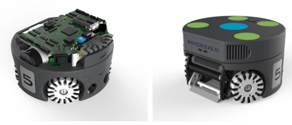
The biggest and most important part of the robot is its main body where all separate parts and the main electronic board, are directly mounted on it. In compare to other parts, this part has the most details.
The Main Body is designed to be compatible for both types of motors, 30W and 50W EC flat Maxon motors, the motors are designed to be as close as possible to the ground to reach the lowest center of mass in the robot. Currently the motors have a distance of 2 millimeters from the ground. Other pieces including the battery and magnetic shooters for chip and direct kicks are also contained inside this part. The magnets need to be optimized to avoid damage on other parts of the robot. [3]
The design of the kicker magnet and its plunger has been changed for making the kicker mechanisms more efficient. The first floor of the main body is designed to have a sufficient space for the plunger to completely get out of the coil when returning to its starting position.
Wheels
One of the major issues in the old robots were inaccurate low-level navigation. After many experiments, measurements and inspections on the control system, it came out that non-identical mechanical properties of each gear are the biggest issue, which was caused by manufacturing inaccuracies. To have smoother and more accurate movement, gear module is redesigned with smaller module size this year. Also there are a little change in sub wheel designs and tolerance to reduce unsteadiness and to stick better to the field during fast accelerations.
The wheels of the robot are also 3D printed except for their gears and sub wheels. The sub wheels are attached to the wheel by pins, there are 15 sub wheels on every wheel of the robot.
As the field size has been increased, higher speeds are inevitable; so the gear ratio is optimized to 72:22 and 50 Watts Maxon EC-45 brushless motors are used to overcome the max-speed/max-acceleration trade off.
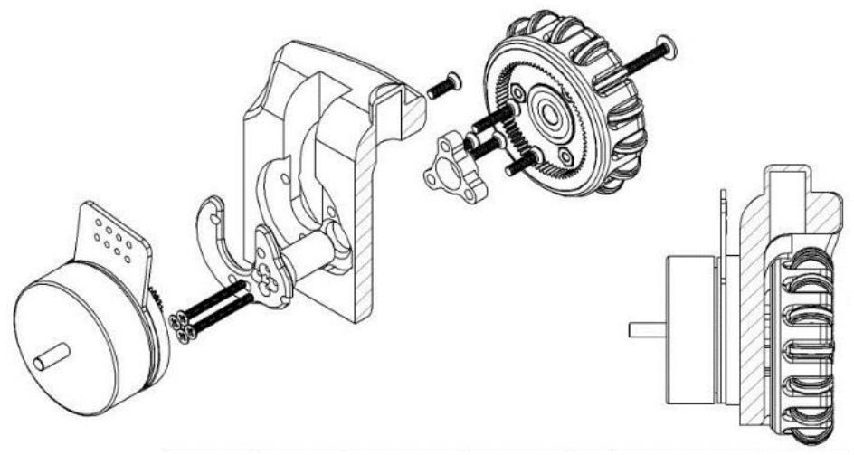
One of the most critical part is the wheel shaft which is reinforced by using four M2 and one M3 screws, the shaft is limited from behind to the motor and is screwed to it, from the front, the shaft is limited by the ball bearing and a single screw which holds the wheel and ball bearing to the shaft (see Fig. 2).
Casing
Although safe navigation has been a must for years in the league, highly dynamic nature of the SSL causes unavoidable collisions that lead to damages ranging from minor to severe. To avoid damages to internal parts, especially electronics which are fragile, making a robust, solid casing that can efficiently damp impacts is a necessity. Thus, a case made up of 2mm thick carbon-fiber compound is made which is as solid as it is light to cover the whole body but kicking devices and the dribbler.
Kicking & Dribbling System
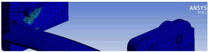
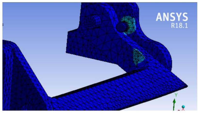
Because of some high voltage short circuit caused by magnet solenoids, our whole kicking system is isolated from body and there isn't any direct metal to metal contact. There is an impact between chip kicker and couple of pins which limit the rotation of the chip kicker this impact caused breaking in chip kickers through years (see Fig.3). The new design of the chip kicker has solved this issue by compensating the stress concentration (see Fig.4).
As we can see in Fig. 3 and 4 in the old design, impacts had a stress concentration and is the reason why the chip kickers break because of its fatigue. The new design also has this concentration but as we can see it is less than the old design.
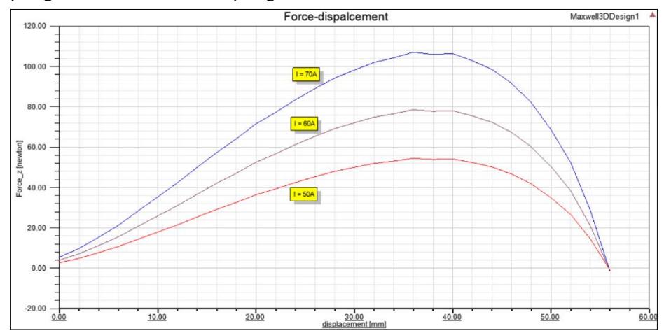
In order to make the kicker device efficient the main work is to transfer the most of the magnetic flux energy into mechanical energy (moving plunger). By simulating kicker magnet device in Ansys Maxwell we found out that the plunger will get more energy if the plungers starting position is completely out of the coil. As the plunger moves into the coil the more force is applied to it by magnetic flux and then it drops like in Fig. 5. In previous design piece of plunger was in the coil at starting position which it caused less energy to transfer. In the Fig. 5. we can see the force applied to the plunger versus the amount of plunger which is in the coil.
By measuring the area under the curve we obtained the energy transferred to the plunger and we were able to find the final ball speed.
Electronics
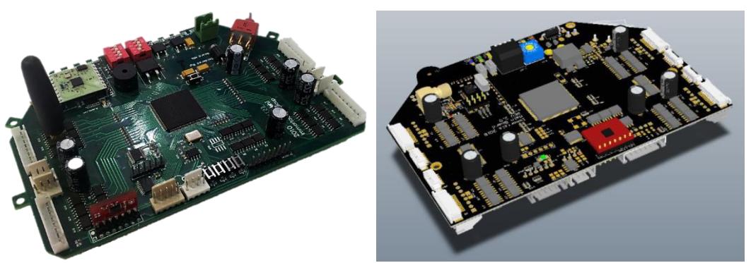
There have been minor changes applied to the electronics including both the main and kicker board for this year. The changes where aimed to fit the needs of the new standard platform robot designs.
The old main board had a single Xilinx XC3S400 chip for handling the sensors, modules and motors. [9] In the new main board an nRF52832 SoC has been implemented beside the Xilinx XC3S400 chip, which works as a wireless communicator and an ARM microcontroller. The nRF52832 controls the I/O switches,
LEDs, nRF(internally), Current sensors and FPGA(Xilinx XC3S400) actions, thus there are more free I/O ports on the Xilinx XC3S400 for handling 6-pin Encoders (Maxon motors internal Encoder) besides 4-pin Encoders (E4T US-Digital Encoder). [4]
Wireless Communication
Robots communicate with the same protocol used in the nRF24l01 module which is widely used in the league, the nRF52832 supports a 2.4GHz multiprotocol radio including the nRF24l01 protocol, which is directly accessed by its ARM processor, thus we are able to connect to the robots regardless of their nRF chip, in the same protocol. [2]
Kicker board
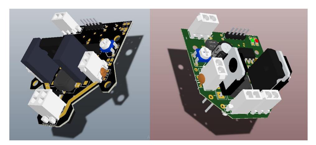
In order to transform electrical energy to kinetic energy, we use two solenoids; one for the direct and the other for the chip kicker. By applying a high current impulse to each solenoid, a strong momentary magnetic field is produced which applies a hard force to a ferromagnetic piece that pushes the ball. The impulse is given by discharging the high voltage capacitors directly to the solenoid using a fast switch IGBT that is controlled by the main board.
To account for the increase in field size, we have redesigned the kicking system and increased the capacitance of the circuit. The charging system is switching DC boost converter, which charges the capacitors. [10]
In RoboCup 2016 Leipzig, we provided four 2200µf capacitors, which took about 8 seconds to charge from 0 to 200V, recently because of the changes applied to the velocity rules, which limited the maximum ball velocity to 6.5m/s we decided to switch back to the old capacitor plan. Thus, currently we are using four 1200µf capacitors, which takes about 5 seconds to charge from 0 to 200V using the new kicker board.
Software & Firmware
Since the main electronic board has been changed from a single FPGA as its main controller to an SoC, serious changes had been applied to the firmware, especially separating the software running on the ARM core of the nRF52832 and the FPGA firmware.
This year we have made changes in the navigation process for a more acceptable maneuver in the robots.
nRF52832
The nRF52832 SoC is built around a 32-bit ARM® Cortex™-M4F CPU. The ARM core is programmed in C and is connected internally to a radio module, its main task is to send and receive the command via the ANT protocol which is the protocol used in the nRF24l01 on our sender and transfers it to the FPGA for operating the motors and shooting system. [2]
FPGA
A Xilinx XC3S400 has been mounted on the main board for controlling the motors, encoders, gyro and kicking system. There is a TSK3000 processor implemented inside the chip for calculating the navigation algorithms and processing data received from the nRF52832. The chip by its self has no non-volatile memory so it uses the nRF52832 for getting its initial data at startup.
Navigation
The navigation of the robot used to be done by sending its target velocity in every command which was being sent after every frame process, thus every 60 times per second the robot receives its new target velocity. This method had some issues in producing a smooth and accurate movement. To solve this problem, we choose to send the movement displacement instead of the targeted velocity. After using this method, the robot has a better view on its movement and runs a PI (PID without the Differentiation) controlling algorithm to reach the target position in the least time.
References
- Zickler, S., Vail, D., Levi, G., Wasserman, P., Bruce, J., Licitra, M., Veloso, M.: CMDragons 2008 Team Description. In: Proceedings of Robocup 2009.
- Nordic semiconductors, www.nordicsemi.com.
- EC 45 flat Maxon motors, www.maxonmotor.com.
- E4T Miniature Optical Kit Encoder, www.usdigital.com/products/encoders/incremental/rotary/kit/E4T
- Ruud Tilburgs, Design and realization of a solenoid for a Robocup kicking device.
- Lenses selection and setup, www.theimagingsource.com/en.
- Bruce, J., Zickler, S., Licitra, M., Veloso, M*.: CMDragons 2007 Team Description. Technical report, Tech Report CM -CS-07-173*, Carnegie Mellon University, School of Computer Science.
- Browning, B., Bruce, J.R., Bowling, M., Veloso, M.: STP: Skills tactics and plans for multirobot control in adversarial environments. In: Journal of System and Control Engineering.
- Niknezhad M.R., Salehi A., GhaziMirSaeed S.A.: Immortals 2016 Team Description
- Falin, J.: Minimizing Ringing at the Switch Node of a Boost Converter. Application report, Texas Instruments Inc. (2006)