KgpKubs 2018 Team Description Paper
Mayank Bhushan, KV Manohar, Sudarshan Sharma, Saurabh Mirani, Ankush Roy, Rahul Kumar, Ashish Kumar Gaurav, Sayan Sinha, Mehul Nirala, Shubham Maddhashiya, Saurabh Agarwal, Chelsi Raheja, Pritam Soni, Tanishq Jasoria, Pranit Dalal, Himanshu Mittal, Adnan Lokhandwala, Vibhuti Singhania, Yash Sharma, Siddharth Agarwal, Prince Agarwal, Shivam Kumar Panda, Harsh Shukla, Dhananjay Kulkarni, Viraj Patel, Shail Takarkhede, Gunjan Sengupta, Ankit Lohani, Rishabh Jain
Indian Institute of Technology, Kharagpur
Abstract This paper describes the mechanical, electronic and software designs developed by Kharagpur RoboSoccer Students' Group (KRSSG) team to compete in RoboCup 2018. All designs are in agreement with the rules and regulations of Small Size League 2018. Software Architecture implemented over Robot Operating System(ROS), trajectory planning and velocity profiling, dribbler/kicker design and embedded circuits over the last year have been listed.
1 Introduction
KgpKubs is a RoboSoccer team from IIT Kharagpur, India. The research group aims to make autonomous soccer playing robots and participate and conduct various related events. Undergraduate students from varied departments and years are a part of this group. We have previously participated in FIRA RoboWorld Cup in the years 2013-2015 in the Mirosot League and secured Bronze Medal in the same in 2015. We have also participated in RoboCup SSL & 3D-Simulation League in Nagoya, Japan 2017. In December 2017 we participated in RoboCup Asia-Pacific in Thailand in the 3D-Simulation League.
This paper is a continuation of last year's Team Description paper and describes the developments made after last year's participation. Mechanical design of the robots is presented in section 2. The firmware and embedded circuits are described in section 3, followed by the software system in section 4. Finally, the discussion and future work are described in section 5.
2 Mechanical Design
The robots are designed in Solidworks. Extensive simulation and testing were done using Ansys (Workbench) and Adams to validate the results.
The robot chassis is manufactured using Aluminium 6061 to ensure the strength of the robot and keep it low weight. All the electrical components are organized in a housing compartment which ensures safety and accessibility inside the robot. Table 1 summarizes hardware configuration of the bot.
Table 1: Robot Hardware
| Dimensions | Dia: 179mm , Height: 149mm |
|---|---|
| Driving motors | Maxon EC-45 Flat (50W) |
| Gear Type | Internal Spur |
| Gear Ratio | 1:3.3 |
| Wheel diameter | 50mm |
| Dribbling motor | Maxon EC-16 (30W) |
| Dribbling gear Ratio | 2:1 |
| Dribbling bar diameter Dia: 14mm | |
| Max. ball coverage | 19% |
| Sub-wheel Diameter | 10mm |
2.1 Locomotion System
The drive system is a four-wheel omni-drive with the rear wheels inclined at 90 degrees and the front wheels inclined at 120 degrees to provide space for the dribbler and kicker mechanism. The motor used for driving is Maxon EC45 (50W). Spur gears are used between wheels and motors with a gear ratio of 1 : 3.3. A significant drawback in last year's robot was the loosening of screws joining the wheel and the shaft after a few minutes of continuous motion. So we redesigned the washer and implemented a new square locker mechanism to correct this problem.
2.2 Dribbling Mechanism
In the previous design, the major problem was that of the ball getting under the dribbler which induced a tendency of backward toppling in the robots. It was fundamentally because of the following two reasons that there occurred incorrect torques and impulsive reaction forces,
- The dribbler rod was not at the correct height from the ground.
- The dribbler had an angular suspension, as a result when it damped the incoming ball, the angle of contact between the ball and the dribbler changed.
The dribbler would lose contact with the ball due to vibrations and insufficient damping. Hence, we completely remodelled our dribbler.
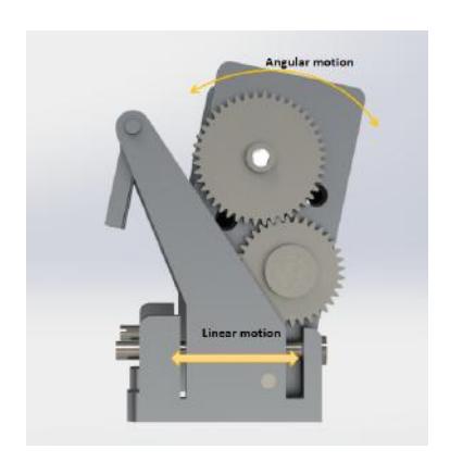
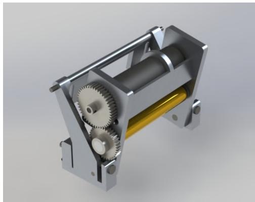
The new model shown in Fig.1, has been engineered to have a linear damping mechanism. It damps by moving horizontally backwards while receiving the ball. In this mechanism, the angle of contact remains constant. In addition to it, an angular mechanism has been implemented so that the height of the dribbler rod can be changed. This helps in setting the best height for the dribbler rod as the environment changes so that it can dribble the ball efficiently. This further gives a decent range of backward and forward acceleration of the robot and hence it does not topple.
The dynamical equations were formulated for the active handling of the ball and hence, the best range of accelerations were attained from −3m/s² to +3m/s². Considering this range and including other factors like coefficient of friction between ball and ground and normal reaction between the ball and the dribbler rod, the best range of angle of contact was calculated and hence the best range for dribbler height. The best range of height for the dribbler rod from the ground is between 27.3mm to 29.3mm. Additionally, The best range of angles is from 0◦ to 20◦. All the results were attained by carrying out analysis in MATLAB.
Further calculations established that the best gear ratio with the motor Maxon EC16 30W and gear-box is 4.4 : 1 which is 9 : 11. For the dribbler material, silicon rubber has been used. Currently, our team is using the previous design in our robots, but the new design will be implemented before RoboCup 2018.
2.3 Kicking Mechanism
Straight Kicker
The straight kicker is powered by two 250V 2200uF capacitors, which can be charged by a step-up converter to 200V each. In the earlier design, we had cylindrical solenoids made of 6061-Aluminium alloy. It had windings of 23AWG copper wire and 680 turns. The design was good and sufficiently robust for kicking the ball up to 8 m/s, but had two major drawbacks:
- Solenoid's frame was made of metal, which resulted in short-circuiting problems.
- Cylindrical solenoids consume a lot of space, so implementing the same dimension of solenoids for both straight and chip kicker becomes difficult.
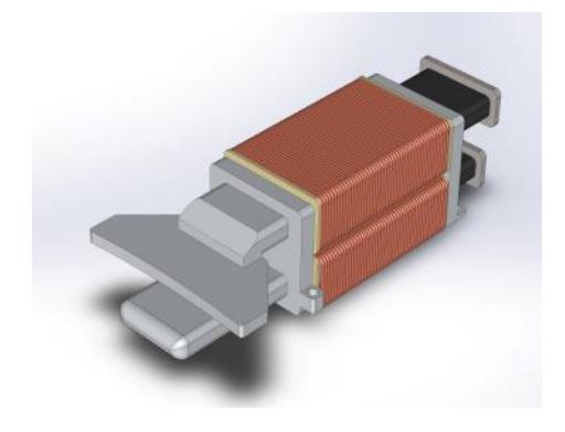
So, to tackle the problems mentioned above and keeping in mind the performance of the solenoid, optimization analysis was carried out using MATLAB. Also, the solenoid's frame would be made out of Polyoxymethylene (POM), which has high structural strength, high stiffness and low coefficient of friction, hence making it ideal for this purpose.
Solenoid Optimization
The goal was to achieve maximum energy generation by the solenoid while keeping the dimensions as a constraint. In order to efficiently use the space available, a rectangular cross-section has been used for the solenoid. The outer dimensions were decided by maximising the volume of solenoids within the available space. Optimization of the inner dimensions was carried out by implementing Finite Element Analysis using MATLAB. The magnetic field was calculated for each elemental volume inside the solenoid and integrated over the volume of the solenoid to get the total flux through the solenoid. By varying the dimensional parameters and taking 23 AWG wire copper wire for the winding, due to its superior performance as mentioned in KPGKubs TDP 2017 [13], the grapgh of Magnetic flux vs breadth vs width of the solenoid was plotted. From the graph, we found that the flux is maximum for l × b × h = 56mm × 40mm × 18mm. Further, the thickness of the winding layers is 3.4mm which sets the inner dimensions of the solenoid.
3 Embedded System
Main controller board
STM32F407VG is used as the processing unit which controls four base motors, dribbler and other peripherals. The communication between the main board and computer is established using Nordic nRF24L01+ radio modules. For accurate kicking, TSOP IR obstacle sensor module has been used to sense the appropriate location of the ball before kicking.
In our previous participation a few problems were recognized like wheel slipping, LiPo overdischarge, and difficulties in programming STM using STLink connectors. To tackle wheel slipping an onboard SD Card have been installed for real-time data logging of the encoder data. Lithium Polymer (LiPo) overdischarge protection circuit is incorporated in the main circuit. The onboard programming circuit is in the prototyping phase so that our main board can be directly programmed using the USB cable.
Power Circuit
A 5-cell 2200mAh LiPo battery is used to power the main controller and the kicker board. In the previous circuit, a comparatively bigger switch was used to turn ON/OFF the power supply. The switch was not robust, resulted in spark and would get damaged on a regular basis. In the present circuit, a relay based switch is integrated because of its low cost, low maintenance and sturdiness.
Motor Controllers
Currently, ESCON 24/2 motor controller module is used to control the four 50W and one 30W BLDC motors used in our robots. These controllers come with a dedicated microcontroller to drive the motor along with great error detection capabilities. The controller throws a lot of error and is not much reliable for the dynamic gameplay involved in SSL. The drivers needs to replaced, the four mentioned motors drivers have been tested succesfully.
- The UC2950 is a Texas Instrument (TI) based IC provides high-current switching with low saturation voltages when activated by low-level logic signals.This driver has the high current capability to drive large capacitive loads with fast rise and fall times; but with high-speed internal flyback diodes, it is also ideal for inductive loads.
- The IR4427 is a low voltage, high-speed power MOSFET and IGBT driver. The output drivers feature a high pulse current buffer stage designed for minimum driver cross-conduction. Propagation delays between two channels are matched. IR4427 was initially tested with N-MOS IRF540N and P-MOS IRF940N. Optimal results were observed. Then the testing with IRF7389 was intitated but the results were not acceptable.
- The MC33035 is a high-performance second generation monolithic brushless DC motor controller containing all of the active functions required to implement a full-featured open loop, three or four phase motor control system(closed loop can be implemented using a companion IC MC33039).This device consists of a rotor position decoder for proper commutation sequencing; temperature compensated reference capable of supplying sensor power, frequency programmable sawtooth oscillator, three open collector top drivers, and three high current totem pole bottom drivers ideally suited for driving power MOSFETs. MC33035 was initially tested with N-MOS IRF540N. Optimal results were observed.
- The A3930 is a three-phase brushless DC (BLDC) motor controllers which can be used with N-channel external power MOSFETs. They incorporate much of the circuitry required to design a cost-effective three-phase motor drive system and have been specifically designed for automotive applications. It was initially tested with N-MOS IRF540N. Optimal results were observed.
Further testing is being done on above-mentioned circuits. The best circuit will be incorporated into the main circuit.
Communication Module
Bi-directional communication have been established between the base station and the robots. Each robot has three nRF24L01+ chips connected on board. Out of three, two are used for receiving data, as opposed to only a single nRF24L01+ chip, and this minimizes data loss. The third nRF24L01+ chip is used to send data back to the base station from each of the robots. The base station too has two nRF24L01+ chips to receive data from the robots. The multiple data-pipes is being used in the nRF24L01+ to receive data from all the robots at the same time. So, this year, the nRF24L01+ chips have been soldered directly on the main circuit, as opposed to using female berg strips, and this prevents it from getting loose when subjected to collisions and vibrations, which was one of the major issues of the previous generation robots.
Kicker Board
The kicker board constitutes of charging and discharging circuit. The circuit has a dedicated ATMega328 microcontroller. The board receives external interrupt trigger and kicking level from the main circuit. The Kicker board charges two 2200uF capacitors using flyback topology up to 200V each. This year the design of circuit has been changed completely. The previous circuit occupied a lot of space, produced electric sparks and required excessive maintenance. Also the charging time of the capacitor was more as compared to the new circuit.
Charging Circuit
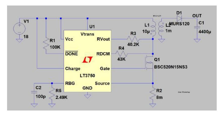
The earlier charging circuit was based on Switch Mode Power Supply (SMPS) and used flyback converter to charge two 2200uF capacitors to 150 volts in sixseven seconds. For switching, Power MOSFETs were used which were controlled by a PWM signal from Atmega with a frequency of 100 kHz. But the circuits were not robust, MOSFETs were damaged frequently and charging time was high which prevented us from kicking frequently. So to improve our circuit and rectify all the problems we switched to LT3750, a capacitor charge controller from linear technology. The LT3750 is a flyback converter designed to rapidly charge large capacitors to a user-adjustable target voltage. It consists of a different resistor which can be used to change various output parameters like charging current. The CHARGE pin one the IC gives full control of the LT3750 to the user and the DONE pin indicates when the capacitor has reached its programmed value, and the part has stopped charging. It also has features like under voltage lockdown and overvoltage protection. Simulations on LTSpice shown in Fig.3 showed improved efficiency and reduced charging time. The new charging circuit is significantly small in size and much more robust and faster than the previous circuit.

4 Software
The following section has the description of the developments and changes made on the software side, since our last participation in SSL. An overview of Finite State Machine (FSM) architecture developed on Robot Operating System (ROS) is presented in subsection 1. Subsection 2 discusses the improvements in vision data processing for updating the world state model. Subsection 3 analyses the controls and the various methods applied for PID tuning. Subsection 4 discusses our GUI development for testing and tuning robots. Subsection 5 is about path planning, mainly the RRT and its variants. Subsection 6 highlights our work on velocity profiling.
4.1 Code Base
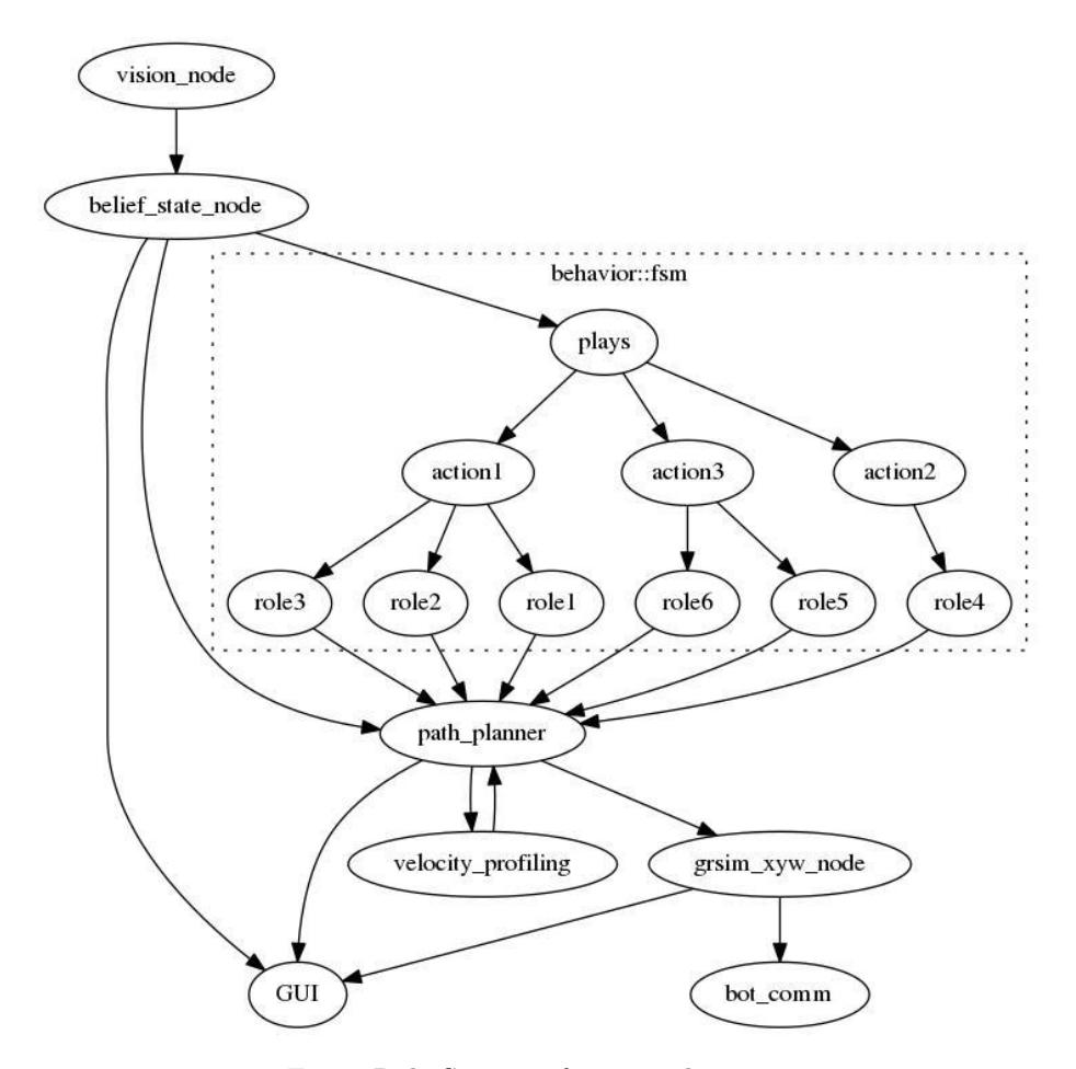
This paper proposes Finite State Machine (FSM)[16] developed on ROS for implementing adaptive robot behaviours. Our software relies on deterministic finite automaton implemented through FSM. This is a generic hierarchical state machine class in which a state comprises of sub-states. Each state is implicitly in its parent state, thus sufficing the polymorphism of state machines.
There are three methods corresponding to each STATE:
- on enter STATE
- execute STATE
- on exit STATE
Each transition edge calls on exit function on parent's state followed by on enter and execute function on its unique child's state. Recursive transitions between states continue until an action has met its target state or termination. Failure of any transition leads to termination.
Issues:
Our previous RoboSoccer software based on naive Skill Tactic Play (STP) architecture had several issues :
- Intercommunication between various skills, tactics and plays was limited, resulting in inefficient coordination between agents.
- For testing a single part of the code, the whole project had to be re-compiled and executed, thus limiting the scope of unit testing.
- All the computations were made on each video frame due to an inefficient structure of the code, making it slow.
Developments:
Software developed on Finite State Machine has the following improvements:
- Independent testing for each Role, Action and Play.
- Computations are currently performed only during the strategic transition of every state.
- The execution of complex strategies has been simplified into a composed form of low-level actions.
Modules:
- state machine comprises the architecture of finite state machine
- roles comprises definitions of simple motions.
- actions consists of definitions of collection of roles.
- plays comprises definitions of plays.
- planners contains definitions of path planners and controllers used by roles.
| – belief state subscribes to SSL-Vision and publishes Belief State information on belief state topic. It includes state of robots and ball along with field parameters and predicates. The state comprises the position and velocity vectors. | | – ssl common contains miscellaneous libraries that are required by several modules such as configuration files, network libraries, serializerdeserializer etc. | | – ssl msgs contains all ROS message definitions required by other modules. Communication on all topics must be through one of these message types. | | – vision comm describes node that publishes vision information to the topic vision and connects to either SSL Vision instance (real robots) or grSim instance(simulator) depending on execution parameters. | | – kgpkubs launch contains launch files and other scripts for launching all nodes on a machine. | | – navigation contains executables for path planners and PID which are used for locomotion. |
4.2 Vision
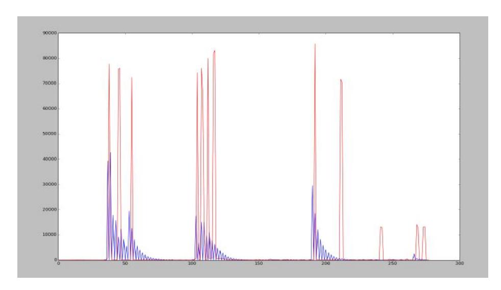
The data captured by the camera is not reliable as it is noisy. This hinders the prediction of robots' positions and velocities accurately. To overcome this problem we tested two filters - the Savitzky–Golay filter and Kalman filter. Though the results obtained from both the filters were almost the same, the Kalman filter was a tad slower and resource heavy as compared to the Savitzky–Golay filter. So, we used Savitzky–Golay filter to keep up with the frame rate.
4.3 PID Control
PID controller [14] calculates and rectifies error in position of robots and applies a correction using proportional, integral and derivative parameter. We have applied this controller to position error of robots independently in the x and y coordinates.
$$\overrightarrow{e} = \overrightarrow{SP} - \overrightarrow{CP} \tag{1}$$
e is the error in position vector, SP is the set point, CP is the current point
Parameters of PID controller were tuned to minimize rise time, overshoot and remove steady-state error in the position of a robot.
For optimizing parameters, Trial & Error and Particle Swarm Optimization (PSO) [15] were tried. In PSO, a swarm of particles is created whose position is initialised randomly in the environment representing constants of PID Controller. Each particle moves based on the best global position of swarm and best local position of particle.
$$v_i(t+1) = wv_i(t) + c_1 r_1[\hat{x}_i(t) - x_i(t)] + c_2 r_2[g(t) - x_i(t)]$$ (2)
i is the particle index, w is inertial coefficient, c1, c² are acceleration coefficients, r1, r² are random values.
For Trial & Error optimization, initially, PID parameters are set to zero. The proportional parameter of PID is increased till steady oscillations are achieved. Consequently, the derivative setting is increased to minimize oscillations in error. The integral parameter of PID is then used to minimize steady state error if any.
$$u(t) = k_p e(t) + k_i \int_0^t e(t')dt' + k_d \frac{d(e)}{dt}$$ (3)
4.4 GUI Development
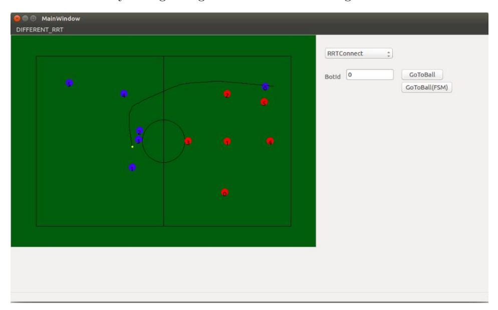
We developed a PyQt based GUI for testing and analysing the performance of variants of the Rapidly Exploring Random Tree (RRT) algorithm. This GUI makes it simple and time efficient to monitor the errors.
Features:
- To test Basic Skills
- Real time analysis of growing tree for various RRT algorithms
4.5 Path Planning
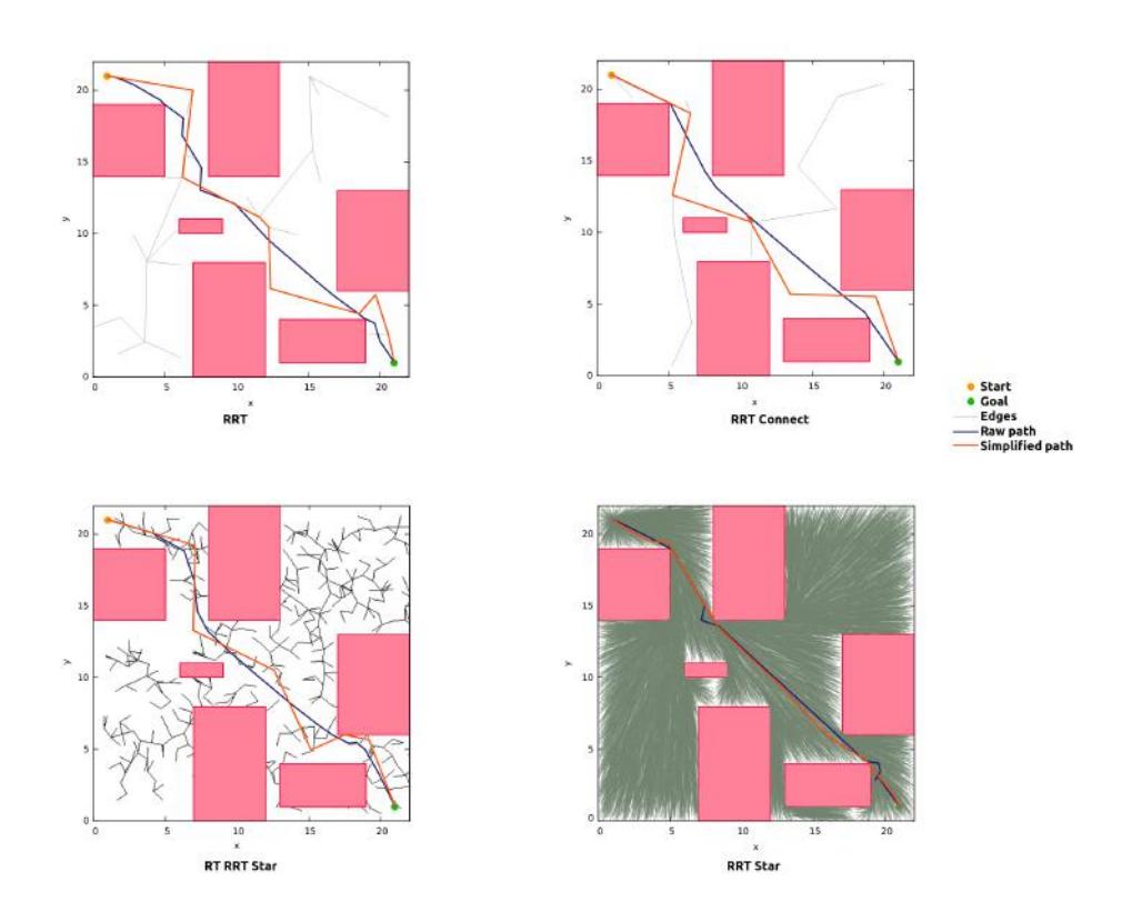
A few path planners were implemented which suited our purposes, including variants of RRT and Kinodynamic planners. Kinetics and dynamics of the robot were difficult to capture in kino-dynamic planners. Hence, we focused on variants of RRT, specifically RRT Connect, Real-Time RRT Star (RT-RRT* with edge rewiring [17]) and RRT Star (RRT*). The efficiency of these planners over the other variants was determined using some preliminary tests. They were developed and integrated with ROS and our GUI. Exhaustive testing on grSim and the robots were done. After generation of a path, it is processed using multiple steps of simplifications and smoothing. In Table 2 we present a set of planners and the time required for path generation and simplification. Figure 7 shows the tree growth and paths formed by the RRT algorithms.
Table 2: Path planners
| Planner | Solution time (in s) | Simplification time (in s) |
|---|---|---|
| RRT | 0.001284 | 0.002113 |
| RRT Connect | 0.000677 | 0.001080 |
| RT-RRT Star | 0.000732 | 0.000963 |
| RRT Star | 5.004750 | 0.000203 |
| LBT RRT | 5.000386 | 0.000319 |
| Lazy RRT | 0.047412 | 0.000328 |
| TRRT | 0.014794 | 0.001864 |
| pRRT | 0.001266 | 0.000875 |
| Informed RRT Star | 5.000174 | 0.000252 |
4.6 Velocity Profiling
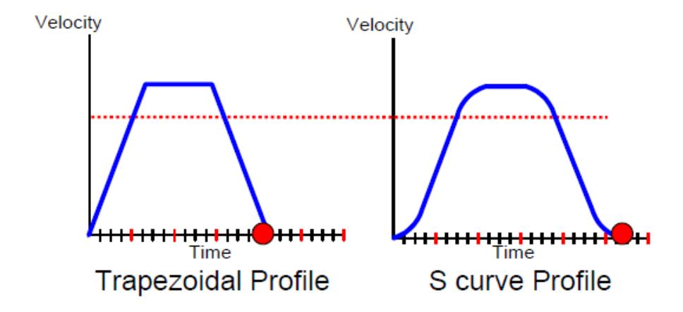
After a detailed analysis of the speed, the performance of S-curve and Trapezoidal Velocity Profile we have implemented the latter one. With adaptive restrictions on Max Velocity and acceleration, it creates a velocity-time mapping for given path, which is used to predict velocity at any instant, meant to be modified by PID after taking in considerations the error in current and expected positions. (Refer Section 4.3).
5 Discussion and Future Works
As future work, it is imperative to explore more dynamics that affect the robot behaviour. On the embedded side, we aim to incorporate variable discharging for controlling the speed with which ball is hit; develop fuzzy-PID controller based on encoder readings; integrate IMU for better state estimation. On the software side, we would improve upon the tracking algorithm and upgrade inter-tactic strategies such as pass-receive.
Acknowledgements
The team also acknowledges the mentorship and guidance of our professors Prof. Jayanta Mukhopadhyay, Prof. Sudeshna Sarkar, Prof. Alok Kanti Deb and Prof. Dilip Kumar Pratihar. This research is supported by Sponsored Research and Industrial Consultancy(SRIC), IIT Kharagpur. We also thank our former team members who made all of this possible.
References
- Brett Browning, James Bruce, Michael Bowling, and Manuela Veloso. Stp: Skills, tactics, and plays for multi-robot control in adversarial environments. Proceedings of the Institution of Mechanical Engineers, Part I: Journal of Systems and Control Engineering, 219(1):33–52, 2005.
- Lindsey Langstaff Ryan Strat Robert Woodworth Justin Buchanan, Sean Csukas. Team description paper, robojackets gt, 2015.
- Tamas Kalmar-Nagy, Raffaello D'Andrea, and Pritam Ganguly. Near-optimal dynamic trajectory generation and control of an omnidirectional vehicle. Robotics and Autonomous Systems, 46(1):47–64, 2004.
- Michele Aicardi, Giuseppe Casalino, Antonio Bicchi, and Aldo Balestrino. Closed loop steering of unicycle like vehicles via lyapunov techniques. Robotics and Automation Magazine, IEEE, 2(1):27–35, 1995.
- Werner Dirk Jan Dierssen. Motion planning in a robot soccer system. A Master's Thesis, Language, Knowledge and Interaction Group Department of Computer Science University of Twente The Netherlands, 2003.
- Marko Lepetic, Gregor Klancar, Igor Skrjanc, Drago Matko, and Bostjan Potocnik. Time optimal path planning considering acceleration limits. Robotics and Autonomous Systems, 45(3):199–210, 2003.
- Christoph Sprunk and Boris Lau. Planning motion trajectories for mobile robots using splines. University of Freiburg, 2008.
- Gregor Klancar, Drago Matko, and Saso Blazic. Mobile robot control on a reference path. In Intelligent Control, 2005. Proceedings of the 2005 IEEE International Symposium on, Mediterrean Conference on Control and Automation, pages 1343–1348. IEEE, 2005.
- Michael Bowling and Manuela Veloso. Motion control in dynamic multi-robot environments. In Computational Intelligence in Robotics and Automation, 1999. CIRA'99. Proceedings. 1999 IEEE International Symposium on, pages 168–173. IEEE, 1999.
- Alessandro De Luca, Giuseppe Oriolo, and Marilena Vendittelli. Control of wheeled mobile robots: An experimental overview. In Ramsete, pages 181–226. Springer, 2001.
- Oussama Khatib. Realtime obstacle avoidance for manipulators and mobile robots. The international journal of robotics research, 5(1):90–98, 1986.
- Brett Browning, James Bruce, Michael Bowling, and Manuela Veloso. STP: Skills, tactics and plays for multi-robot control in adversarial environments
- KGPKubs Team Description Paper, RoboCup 2017 Symposium.
- PID Control System Analysis, Design, and Technology, Kiam Heong Ang, Gregory Chong , Student Member, IEEE , and Yun Li , Member, IEEE
- Tuning of PID Controller Using Particle Swarm Optimization (PSO),Mahmud Iwan Solihin, Lee Fook Tack, Moey Leap Kean
- RoboJackets 2015 Team Description Paper,Matthew Barulic, et. al.
- RT-RRT*: A Real-Time Path Planning Algorithm Based On RRT*,Kourosh Naderi, et. al.
- STM32F407VG Datasheet, July 2017. www.st.com/resource/en/reference manual/dm00031020.pdf
- nRF24L01+ Product Specification v1.0, 2008. http://www.nordicsemi.com/eng/Products/2.4GHz-RF/nRF24L01P
- Andre Ryll, Mark Geiger, Nicolai Ommer, Arne Sachtler, Lukas Magel. TIGERs Mannheim - Extended Team Description for RoboCup 2016, 2016