MRL Extended Team Description 2018
Amin Ganjali Poudeh, Vahid Khorasani Nejad, Arghavan Dalvand, Ali Rabbani Doost, Moein Amirian Keivanani, Hamed Shirazi, Saeid Esmaeelpourfard, Meisam Kassaeian Naeini, Aras Adhami-Mirhosseini
Islamic Azad University of Qazvin, Electrical Engineering and Computer Science Department, Mechatronics Research Lab, Qazvin, Iran
Abstract MRL Small Size Soccer team, with more than nine years of experience, is planning to participate in 2018 world competitions. In this paper, we present an overview of MRL small size hardware and software design. Having attained the third place in 2010, 2011 and 2013, second place in 2015 and first place in 2016 competitions, This year we enhanced reliability and achieved higher accuracy. Due to the great changes in the rules, We made major changes to the software. Finally, by overcoming electronic and mechanical structure problems, We promoted the ability of the robot in performing more complicated tasks.
1 Introduction
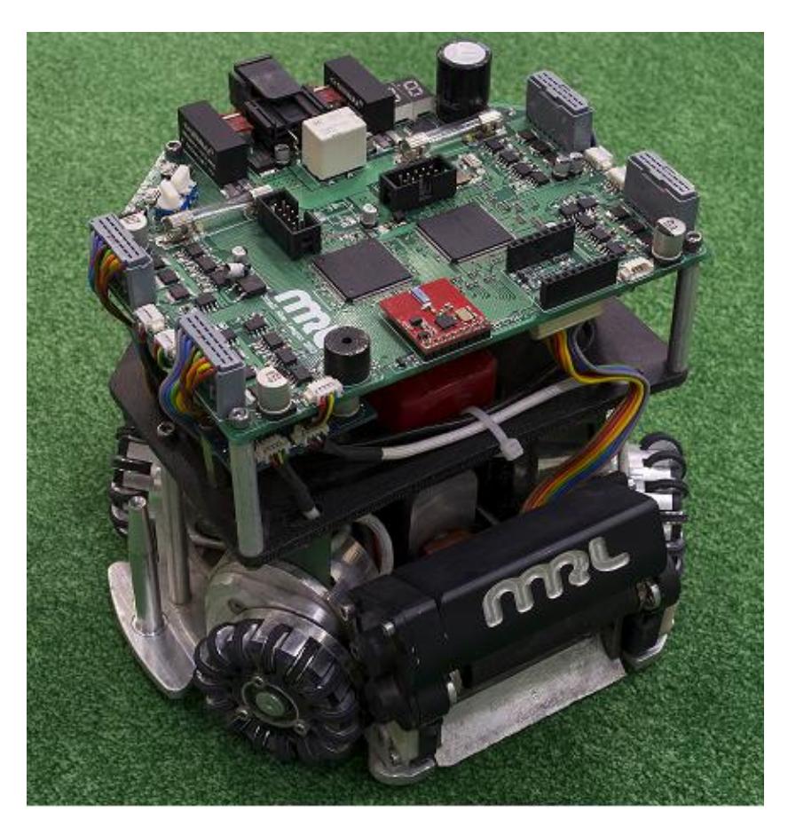
MRL team started working on small size robots from 2008. In 2016 RoboCup, the team was qualified to be in the final round and scored in the first place. In the last competition in Germany MRL team placed in the top 3 teams. In the upcoming competitions, the team goals are having more dynamic and intelligent behavior. In 2018 competitions the main structure of the robots is the same as last year, see [1] for details Figure 1 shows the MRL 2016 robots.
Some requirements to reach this target are achieved by redesigning the electrical and mechanical mechanisms. Moreover, simple learning and optimization approaches are employed in the way of more dynamic play. Evaluation by software tools, like simple motion planner and Strategy originator based on artificial intelligence.
This paper is organized as follows: First of all, the software contains new visualizer and logger description 2. The Electrical design including ARM micro controller, and other accessories of robots onboard brain is explained in section 3. Description of new wheels and mechanical structure, which modifies the capabilities of the robots dribbler system, is the subject of section 4.
2 Software
In this part the software main objects are presented. It is shown that how our new modifications provide us a more intelligent and flexible game. In this year MRL software team has not changed the AI main structure. The game planner as the core unit for dynamic play and strategy manager layer is not changed structurally, but some new skills and abilities are added to the whole system. In this section, after a brief review about the AI structure, short description of the unchanged parts are presented and references to the previous team descriptions are provided. Finally major changes and skills are introduced in details.
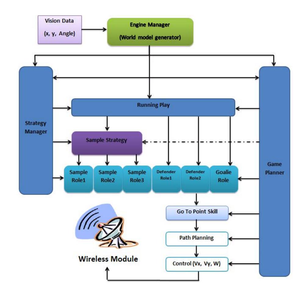
The software system consists of two modules, AI and Visualizer. The AI module has three sub-modules being executed parallel with each other: Planner, STP Software (see [6]) and Strategy Manager. The planner is responsible for sending all the required information to each section. The visualizer module has to visualize each of these sub-modules and the corresponding inputs and outputs. The visualizer also provides an interface for online debugging of the hardware. Considering the engine manager as an independent module, the merger and tracker system merges the vision data and tracks the objects and estimates the world model by Kalman Filtering of the system delay. Figure 2 displays the relations between different parts. In this diagram, an instance of a play with its hierarchy to manage other required modules is depicted. The system simulator is placed between inputs and outputs and simulates the entire environment's behavior and features. It also gets the simulated data of SSL Vision as an input and proceeds with the simulation.
2.1 Simple Motion Planning
according to growing the field size and number of the robots, Our previous system it was not efficient and, less cost-effective and more efficient way. A number of previous problems can be found below:
- Due to a lot of processing, we had to use a special GPU (Graphics processing unit) and we could not use this motion planner on any computer.
- Use of old and outdated technology.
For these reasons, we needed to rewrite the whole motion planner. We decided to use a method that would cost less and find an efficient motion. We prefer to use CPU for motion planning processes. But before using the RRT, we have another way to find the simple path.
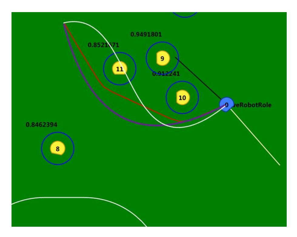
At the beginning number of simple paths has been generated in order to a robot and the target which is consisting of a straight line, polynomial curves(up to third-degree equation) and also sinus curves. Next, each path is being checked by all obstacles in the field and in the next stage, an optimization finds the best path with respect to our parameters and cost function. If every curve has collision then we start to use RRT(Rapidly Random Tree) otherwise, Velocity and instantaneous acceleration has been calculated by result of first and second derivation of path equation and finally they return as control parameter to lowlevel control unit. For instance:
$$Y = x^2$$
Speed Constraints are being considered as bellow:
$$V_x^2 + V_y^2 \leqslant V_{max}^2$$
$$V_Y = 2x \cdot V_x$$
$$(2 \cdot x \cdot V_x)^2 + V_x^2 \leqslant V_{max}^2$$
$$4x^2 \cdot V_x^2 + V_x^2 \leqslant V_{max}^2$$
$$V_x = \left(V_{max}^2 \setminus 4x^2 + 1\right)^{\frac{1}{2}}$$
Also acceleration Constraints are being considered as bellow:
$$a_x^2 + a_y^2 \leqslant a_{max}^2$$
$$a_y = 2V_x^2 + 2x \cdot a_x$$
$$(2V_x^2 + 2x \cdot a_x)^2 + a_x^2 \leqslant a_{max}^2$$
$$(4x^2 + 1) \cdot a_x^2 + (8x \cdot V_x^2) \cdot a_x + 4V_x^4 \leqslant a_{max}^2$$
where:
Vx: Linear Velocity of x
Vy: Linear Velocity of y
ax: Linear Acceleration of x ay: Linear Acceleration of y
amax: Maximum Linear Acceleration of Robot
x: Position of x
Our new motion planner decreases the complexity of processes because it does not have any intermediate points like RRT additionally the improvement increased the speed of robots to move through the pass.
2.2 Strategy originator
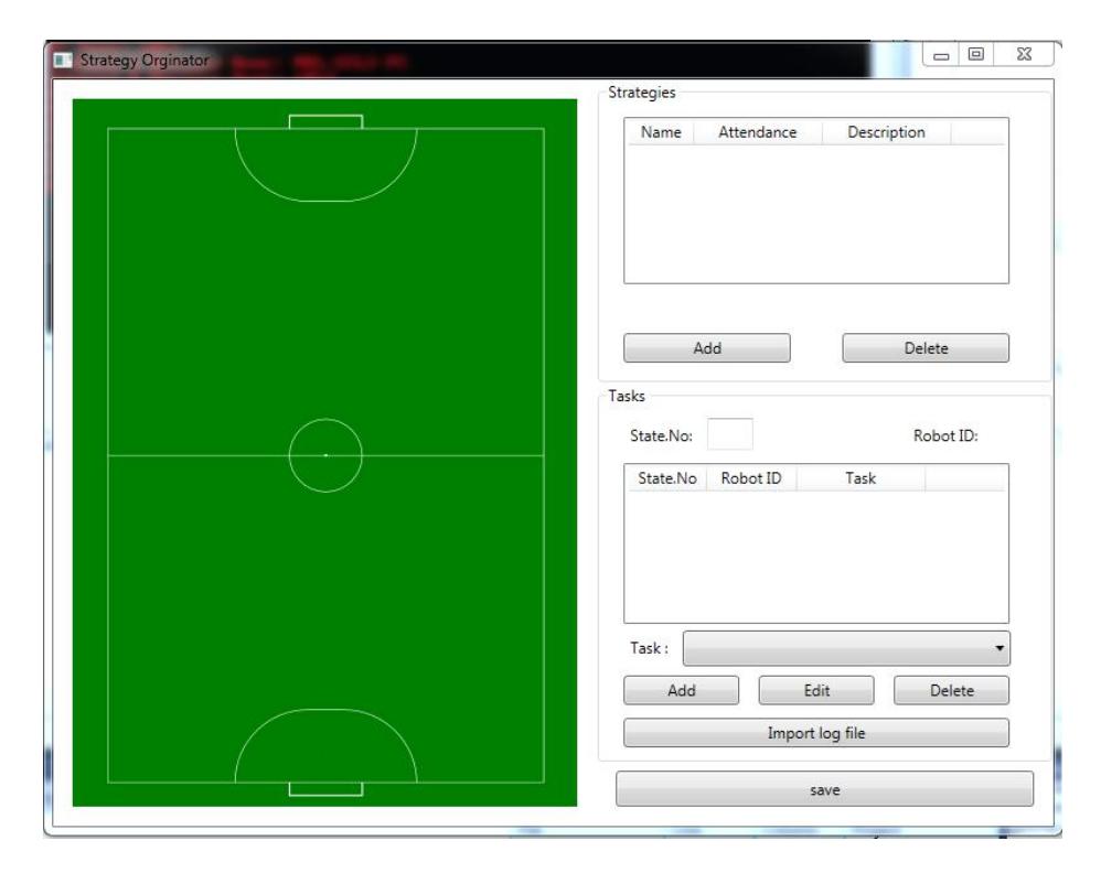
As the field grows and the number of robots will increases to 11 in the next year, The league is on the way to approaching real football.We designed a software where we can adjust the number of assailants, the starting position of the ball and the motion of the robots. Also, considering the logs of the past games, which are available from the teams, at the free kicks which the passes successfully reaches the targeted attackers, the way for misleading the defense will be discovered.And without the need to write a strategy, by giving these logs to the software, that gives the number of The aggressor and region of the placed ball and finds the robot next moves and creates a similar strategy.
This software helps us to analyze other teams better than ever, and score them from their weaknesses. also with the help of this software, we can make new aggressive strategies in a visual environment with defining the moves and tasks for every robot, in little time. In the next phase, the learning system is supposed to be implemented based on the recent logs of the opponent team in order to identify the weaknesses of the defense and generate strategies to score.
2.3 Intelligent defending algorithm
In Small Size League matches (like real soccer games) attacking strategies are very flexible and dynamic. This matter implies that the defense strategies should be dynamic too. In fact, there are lots of unforeseen states that cannot be considered in advanced. Thus, defenders cannot classify all of them to have suitable react. Between the defense skills, positioning is the most important one. Positioning is the sequence of finding the target(s), selecting the blocking strategy. In this year we are going to add prediction part in our defense that predicts the position from last plays of opponents, We give the system some log from latest games of opponent and this new system returns positioning for all defenders for every strategy of opponent, Of course a human must check the result and correct malicious predictions.
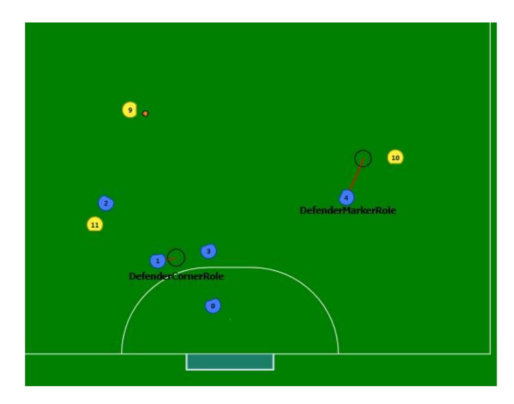
Generally, we have two type of defender, one is to stick to an opponent's robot as a marker called DefenderMarker and the other is that the defender blocks the opponent from the shoot at a great distance called DefenderCorner.
In this algorithm, according to several parameters of the passer and the probable robot that will hit the final ball, one of these two types of the defender will be chosen to deflect the ball.
For example, when the forward striker moves forward and moves quickly to the side of the specified area and strikes the ball, we use the DefenderCorner to deflect the ball.But when the target striker stays in a certain place for the pass we use DefenderMarker which blocks the ball to the striker and seizes the ball and along with defending, it also helps to attack.
We created a software based on the past logs of the opponent's team, by giving the correct roles to the defenders, it simulates the scene several times several times, Until the best defense is found.
In the second phase, we will be able to look at some of these scenarios and correct it if there is a mistake and the application will learn from The correction.
3 Electronics
MRL robot electronic consists of an Altera Cyclone FPGA linked to an ARM core the same as previous years. Changes during last year in this section are implementation of parallel motor controllers in FPGA, since calculation of PID controllers in software requires a lot of CPU time. Moreover, moving controllers to FPGA, the ARM processor can be dedicated to other tasks with fewer interrupts. The other changes are using frequency IR sensor for ball detection and some modifications on the wireless board. For unchanged parts of the electronics see [2] and [1].
3.1 Wireless Board
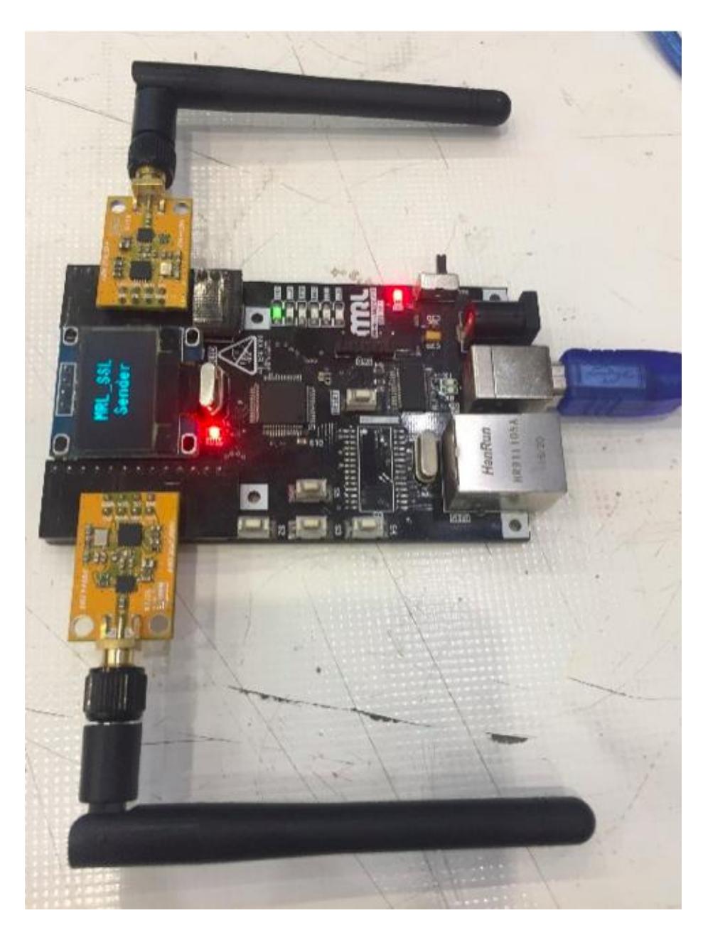
Last year In order to have a stable two-sided communication we used a new nRF24l+ module but we didnt reach the performance we were looking for, So we designed a new wireless board using an STM32F4 instead of LPC2378 in order to have the faster processor and a more stable high-speed air-data transfer. STM32F405 Micro-controller is featured more than the LPC2378 Microcontroller. STM32F746ZG is operating up to 168MHz frequency but the old Micro-controller were operating up to 72MHz. We have also changed the communication between the server and wireless board using an FT232 chip (Serial to UART Converter) and the air-data form so now we can handle more robots faster than before.
3.2 Capacitor Charger Board
Preparing for the new field size, we decided to have longer chip kicks so we had to make some changes in charger board beside the mechanical system and more specific in MOSFET driving and we did so. We have used a more powerful solenoid by increasing the radius and number of turns. Overall, by changing the solenoid and decreasing leakage in MOSFET driving we have better chip kicks.
4 Mechanical Design and construction
Typically, the main portions of the mechanical structure of a small size robot, include 4 wheels, two kickers, a dribbler and the motion transformer system. Regarding the league rules, the diameter of the robot is 179mm and the height is 140mm. The spin back system conceals 20% of the ball diameter in the maximum situation.
Due to some drawbacks in the previously proposed design, we have decided to improve both the mechanical design and the construction materials. Main changes in the mechanical structure of the robot are described in the following paragraphs. The other parts are the same as 2014 robot described in [1].
4.1 Dribbling system
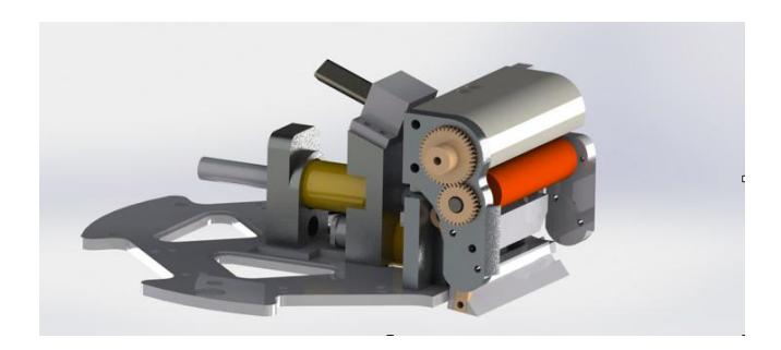
last year we had some problems with our dribbling system. The problem was that the robot could not able to carry the ball on all kind of carpets. So we decided to design a suspension system for it. Now our dribbling system has a suspension that shown in Figure 7. in this new system we can easily change the height of the dribbler and fix it in our desire position based on the carpet. As it is shown in Figure 7, the dribbler is a steel shaft covered with a rubber and connected to a high-speed brushless motor shaft, Maxon EC16 Brushless. Since the spin back motor is on the front side of the robot, it is exposed to the strikes caused by the collision with the ball or other robots. To solve this problem, we took the spin back motors position a little back and designed a shield for it. To improve the capability of spin back to control the ball, we made a construction in which the amount of damping is controlled. the advantage of this system is that now we can control incoming pass up to 6m/s speed that we couldn't before.
References
- Ganjali Poudeh, A., Beik Mohammadi, H., Hosseinikia, A., Esmaeelpourfard, S., Adhami-Mirhossein, A.: MRL Extended Team Description 2014. Proceedings of the 17th International RoboCup Symposium, Jao Pesoa, Brazil, (2014).
- Ganjali Poudeh, A., Asadi Dastjerdi, S., Esmaeelpourfard, S., Beik Mohammadi, H., Adhami-Mirhossein, A.: MRL Extended Team Description 2013. Proceedings of the 16th International RoboCup Symposium, Eindhoven, Netherlands, (2013).
- Adhami-Mirhosseini, A., Bakhshande Babersad, O., Jamaati, H., Asadi, S., Ganjali, A.: MRL Extended Team Description 2012. Proceedings of the 15th International RoboCup Symposium, Mexico city, Mexico, (2012).
- Ahmad Sharbafi, M., Azidehak, A., Hoshyari, M., Bakhshande Babersad, O., Esmaeely, D., Adhami-Mirhosseini, A., Zareian, A., Jamaati, H., Esmaeelpourfard, S.,: MRL Extended Team Description 2011. Proceedings of the 14th International RoboCup Symposium, Istanbul, Turkey, (2011).
- Zarghami, M., Fakharian, A., Ganjali-Poudeh, A., Adhami-Mirhosseini, A.,: Fast and Precise Positioning of Wheeled Omni-directional Robot With Input Delay Using Model-based Predictive Control. Proceedings of the 33th Chinese Control Conference (CCC), pp. 7800–7804, Nanjing, china, (2014).
- Browning, B., Bruce, J.; Bowling, M., Veloso, M.M.: STP: Skills, Tactics and Plays for Multi-Robot Control in Adversarial Environments. Robotics Institute, (2004).
- InvenSense Inc: MPU-6000 and MPU-6050 Product Specification Revision 3.4, 2013.
- Utilizing a Vishay IrDA Transceiver for Remote Control. Application Note by Vishay Semiconductors, Doc. No. 82606, (2014).
- Nordic Semiconductor: nRF24L01+ Product Specification v1.0,(2008)
- LLC Allegro MicroSystems: A3930 and A3931, Automotive Three Phase BLDC Controller and MOSFET Driver, A3930 and A3931 Datasheet
- LLC Allegro MicroSystems. A3930 and A3931 Automotive 3-Phase BLDC Controller and MOSFET Driver, A3930-1 Demo board Schematic/Layout