OMID 2018 Team Description
Ali Mollajafai, Mohammad Hossein Zahedi, Alireza Fatollahzade, Rasoul Aboutalebi, Alireza Sahebi, Amir Mohammad Biuki, Javad Rahmani, Omid Mahdizadeh, Faeze Gholamrezai, Maryam Akhoundian, Mohadeseh Khandani, Reyhane Davarzani, Azam Aliakbari
Department of Electrical Engineering of Shahed University of Tehran, Iran; Department of Computer Science of Shahed University of Tehran, Iran; Department of Computer Engineering of Shahed University of Tehran, Iran; Department of Electrical Engineering Islamic Azad University Science and Research Branch; Department of Electrical Engineering of Khaje Nasir University of Tehran, Iran
Abstract This paper is an explanation of OMID 2018, Robocop small size team, technical estate and robots technical improvement which generally divided into three part: Mechanical part, Electronic part and Software part.
1 Introduction
Omid Robotics Team (ORT) began small size team in 2007. ORT has been participated in competitions since 2007 as a branch of robotics society of Department of Electrical Engineering of Shahed University. The team is located in Tehran, Republic Islamic of Iran. The previous work of the team was used as reference.
We are willing to invite talented students. In addition, newcomers are mentored by former members. This article describes the team's general information and improvements in this year. The designed robot systems of ORT consist of three major parts: mechanics, electronics and software.

2 Mechanical Design
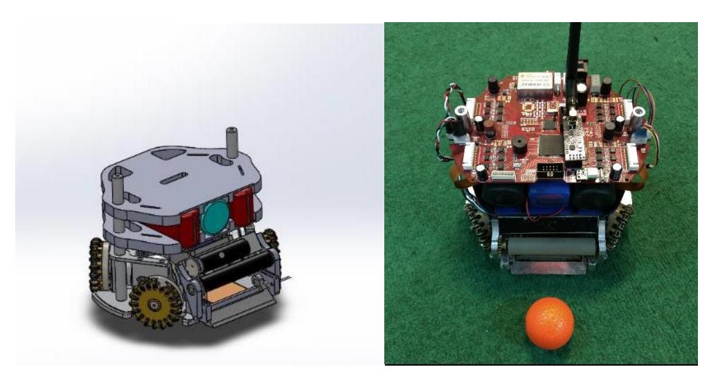
According to Small-Size League rules, the robots must have specific dimensions. Our robots have a diameter of 178mm and height of 148mm and each robot covers less than 20% of ball. The whole robot is about 2 kilograms weight. 3D simulation models shown in Fig. 1 are created with Solid Works.
2.1 Kicking System
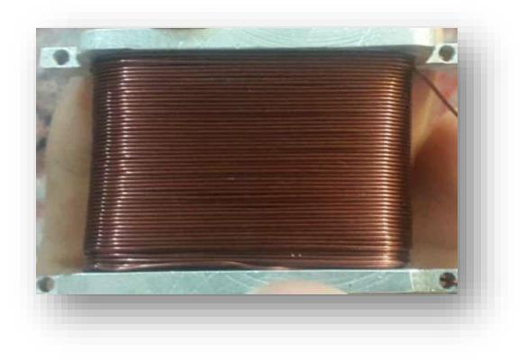
The electrical design for this year has focused on increasing the kick power and reducing the time taken to fully charge the capacitor. In order to reduce the resistance, we decreased the thickness of wires in inductors from 28 AWG to 21 AWG for chip kick and to 23 AWG for direct kick. Also, the charge voltage and the time taken to fully charge the capacitor have been decreased. The charge voltage is 170 and time taken to fully charge is 4 seconds. Generally, increasing the number of turns enlarges the magnetic field. Therefore, we increased the number of turns to 10 for chip kick and to 8 for direct kick. As a result, kicking system has been improved completely. Fig. 3 illustrates a view of new kicking inductor.
3 Electrical System
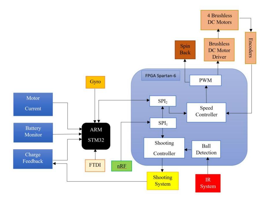
Robots consist of three general parts: Communication, Main board and Kick board. In the main board we use FPGA Xilinx Spartan 6 XC6SLX9-2TQG144I [1], STM32F103 ARM processor, motor drivers, etc. A 4-cell li-polymer battery (1500 mAh) used as the power supply. The block diagram of robot's electrical hardware is shown in Fig.3.
3.1 Main Board
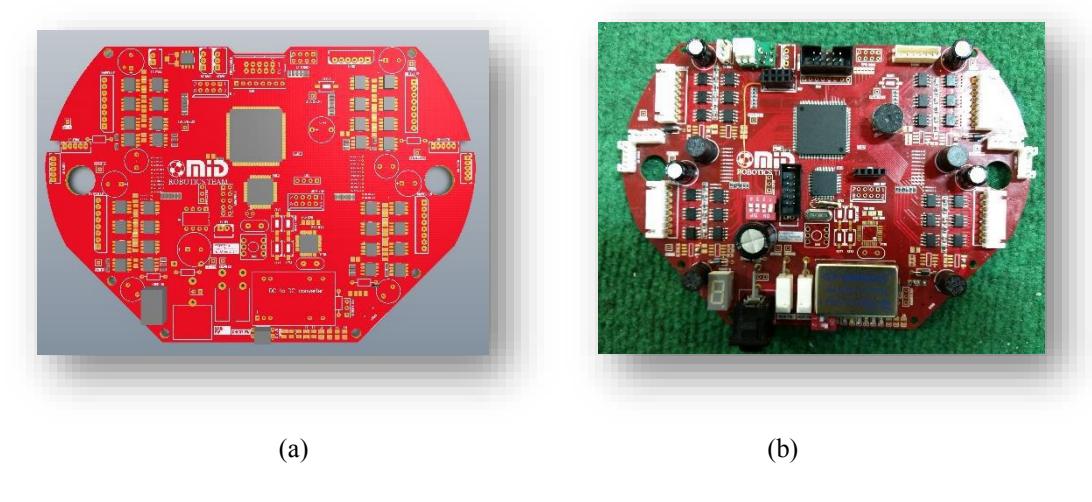
In the main board, we have used FPGA (Spartan 6) as the central controller that controls motors and shooting system by Pulse Width Modulation (PWM) technique. We have solved almost all the previous board problems in our new PCB design. In order to achieve an efficient better design, we have used a 4 layer PCB.
In FPGA, we have applied some code optimization and changed controller operational speed as described in the following section.
3.2 Speed Controller
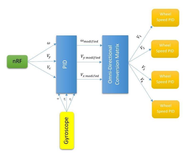
The new generation of kicker board employs ARM processor. Basically, we established a communication protocol between ARM processor and FPGA. Clearly, the goal is to:
- Optimize performance of the process (by dividing duties between ARM and FPGA)
- Receive battery voltage
- Receive current of motors, etc.
3.3 Kicking System
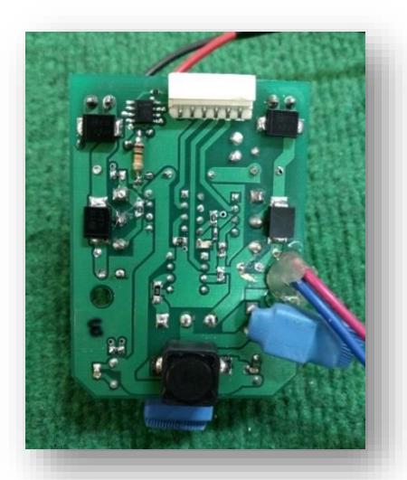
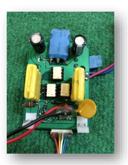
In Our previous system, capacitor charging was controlled through an external ADC (AD7999) which was connected to FPGA. However, the main board was faulting and being affected by noises. To resolve these problems, we decided to control our charging through an ARM system by using the ADC which results in a better performance and improved accuracy.
In order to resolve the shortage of interior space, we designed a new board which occupies less space. Moreover, we resolved failure due to routing overcurrent.
3.4 Ball Detection System
To design a ball detection sensor, we have two practical solutions:
- Using a laser diode and photo-transistor
- Using infrared (IR) LED and Receiver
In our previous design, we had tried first solution and designed a circuit using a laser diode and phototransistor. Unfortunately based on our results, this approach caused a problem when the ball hit the kick part of the robot. So, the two elements were removed from the line of sight, and no longer employed. Furthermore, transistor burns up due to the high sensitivity of the photo-transistor to the high temperature during soldering.
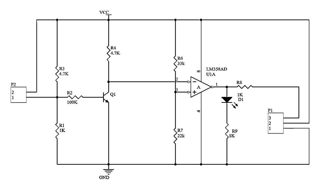
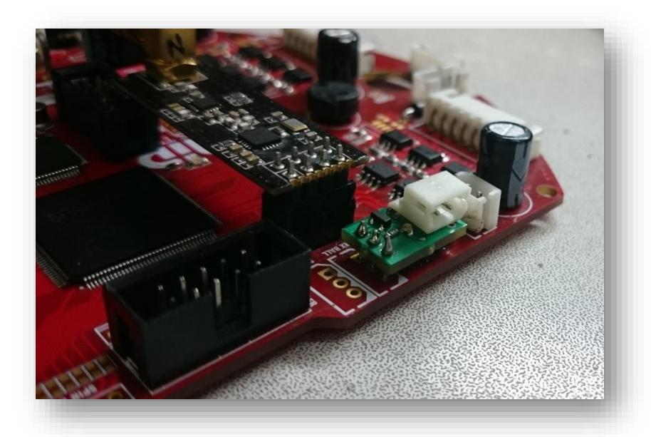
Since we had faced such problems, we tried the second solution. Therefore, we designed a new circuit and performed the necessary tests, including durability to shock and deviation of the two elements, and achieved acceptable results. Another reason that we took advantage of this circuit instead of previous one was the use of a receiver of 3 mm (instead of 5 mm). Also, we designed a comparator by using an OPAMP and two resistors (R6, R7) that the ball detection responds appropriately to the output. The schematic design of new ball detection circuit is shown in Fig.7.
4 Software
Software team decided to migrate to Windows because of its fluency and reliability in developing. On the other hand, the previous core of software became erratic during years. Moreover, so many bugs made difficulties for the development of previous core. Consequently new software core was designed with new features, like modularity, new algorithms, etc.
The software design focuses on the following areas:
- Motion control
- Path finding
- Modular Graphical user interface
- Game plan for robots
4.1 Software Overview
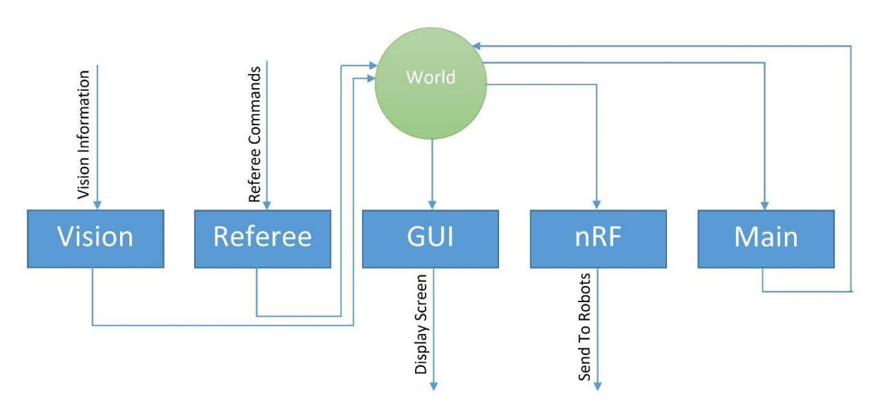
Software has five main sections that work as five threads:
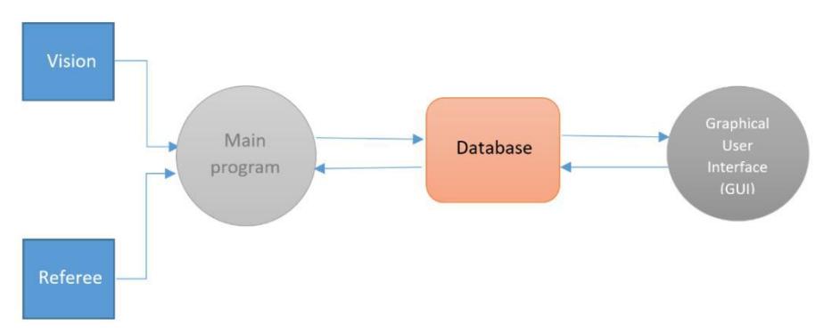
- a) Vision: receives data from SSL-vision and stores the information in world module.
- b) Referee: receives commands from referee and stores them in world module.
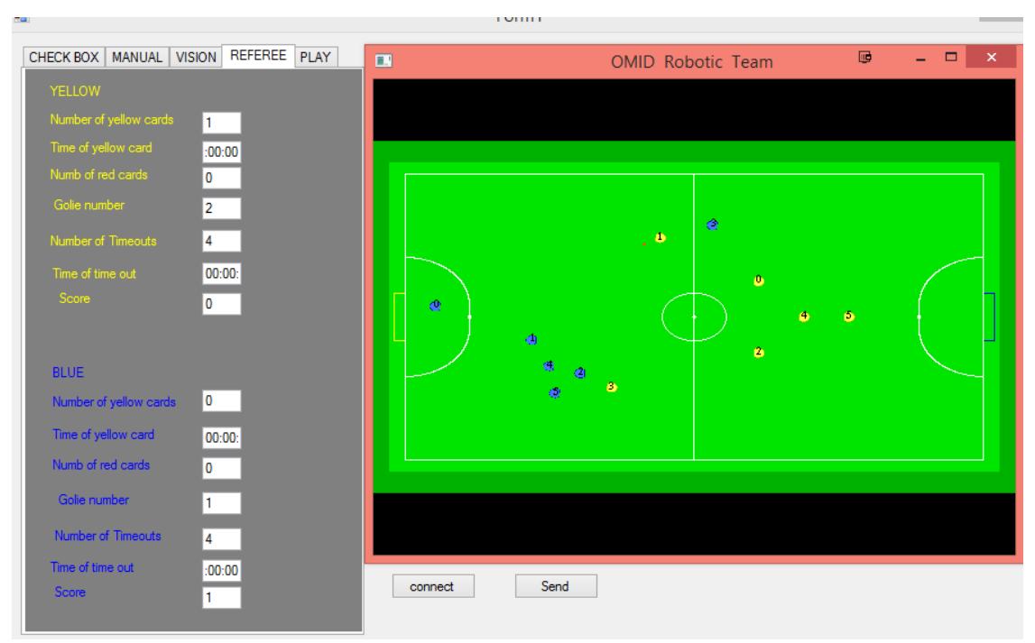
- c) GUI: receives information from world module and shows them on screen, like: position, number and angle of robots, number of yellow and red cards, number of goals for each team, etc.
- d) nRF: receives information from world module and sends them to robots.
- e) Main
Two or more threads need a couple of data. In fact, this data consists of robot information such as position and angle, referee commands, commands for robots, etc. Hence, we store them in a memory called "World module".
4.2 "Main" Section
4.2.1 Decision layer & Functions:
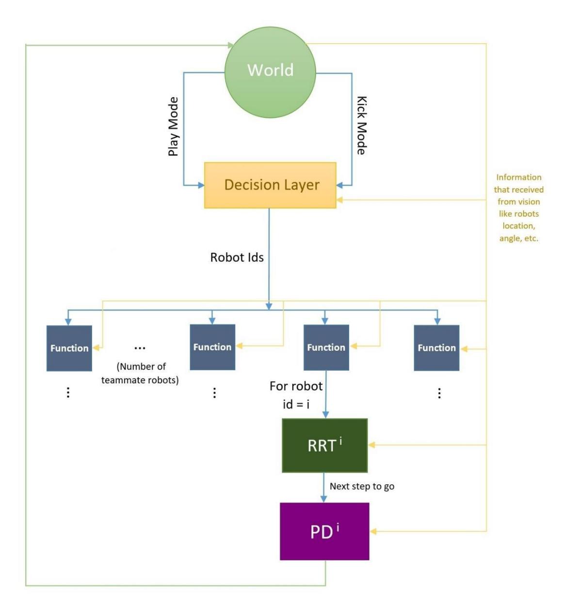
During the game, software core determines a game plan. Depending on robots position, ball position and other effective parameters, a task is assigned to each robot. In the next step, functions determine some low level parameters (like motion vector) to robots depending on robot's duty.
In comparison with our previous software core, the dynamic change in the number of teammate robots during the game is one of our main improvements.
Future plan in software team is using fuzzy logic to get better game plan for robots. By this, each robot knows what to do in every possible situation.
4.2.2 Pathfinding
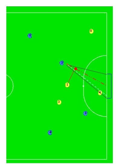
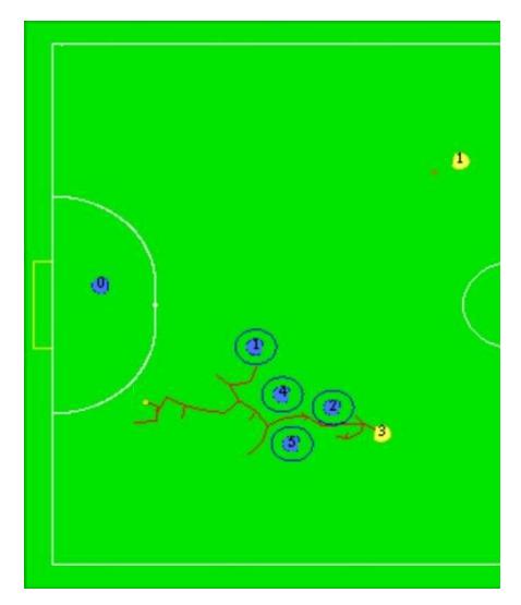
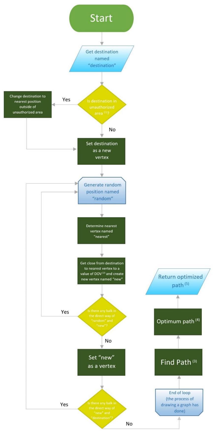
In movement of robots between two points, there might be some obstacles in the robot's straight path between robot's position and destination of robot. So robots should move in paths that don't hit the obstacles.
We use RRT (Rapidly-exploring Random Tree) [9] algorithm to find the paths. In this algorithm, we create a graph that its vertices are points on the field and edges are paths between them.

4.2.3 Motion control
We use PID controller [10] as a motion control of our robots.
The distinguishing feature of the PID controller is the ability to use the three control terms of proportional, integral and derivative influence on the controller output to apply accurate and optimal control.
The overall control function can be expressed mathematically as:
$$u(t) = k_p * e(t) + k_i * \int_0^t e(t) dt + k_d * \frac{de(t)}{d(t)}$$
Since the robot mainly aimed at forward moving path and destination, the 'I' term is not useable and we use PD control system.
k_p and k_d coefficients in formula are calculated by trial and error method.
4.3 GUI
References
- Xilinx : Spartan-6 FPGA Family data sheet
- Li Wang, Zheng Zhang, Ping Sun: Quaternion-Based Kalman Filter for AHRS Using an Adaptive-Step Gradient Descent Algorithm
- Nordic Semiconductor. : nRF24L01+ Single Chip 2.4GHz Transceiver Product Specification v1.0 (2008).
- Sebastian THRUN, Wolfram BURGARD, Dieter FOX. : PROBABILISTIC ROBOTICS.
- Rudy Severns. : DESIGN OF SNUBBERS FOR POWER CIRCUITS.
- Kanjanapan Sukvichai, Piyamate Wasuntapichaikul, Yodyium Tipsuwan. : IMPLEMENTATION OF TORQUE CONTROLLER FOR BRUSHLESS MOTORS ON THE OMNI-DIRECTIONAL WHEELED MOBILE ROBOT
- Li-Chun Lai, Chia-Nan Ko, Tsong-Li Lee, Chia-Ju Wu. : Time-Optimal Control of an Omni-Directional Mobile Robot.
- Omid Robotics Team. : OMID 2017 Team Description paper. Technical report, ECE Department, Shahed University of Tehran, 2017.
- LaValle, Steven M: "Rapidly-exploring random trees: A new tool for path planning". Technical Report. Computer Science Department, Iowa State University.
- Araki, M: "CONTROL SYSTEMS, ROBOTICS AND AUTOMATION" Volume II PID control.