RoboFEI 2018 Team Description Paper
Guilherme P. de Oliveira, Vin´ıcius M. Alves, Danilo Pilotto, Lucas A. da Silva, Julia B. Drapella, Danilo R. Vassoler, Igor do N. Alves, Raphael B. Bezerra, Fernando T. H. Darsono, Wesley de S. Motta, Maria Eduarda T. de C. Daltro, Guilherme C. Garcia, Leonardo da S. Costa, Lucas G. Pinto, Guilherme Luis Pauli, Marcos A. P. Laureano, Carlos Alberto F. Cadamuro, Ana Paula C. K. Santos, Reinaldo A. C. Bianchi, Pl´ınio Thomaz Aquino Junior, Flavio Tonidandel
Robotics and Artificial Intelligence Laboratory Centro Universit´ario da FEI, S˜ao Bernardo do Campo, Brazil
Abstract This paper presents the current state of the RoboFEI Small Size League team as it stands for RoboCup International Small Size League competition 2018, in Montr´eal, Canada, as well as works that are still under development. The paper contains descriptions of the mechanical, electrical and software modules, designed to enable the robots to achieve playing soccer capabilities in the dynamic environment of the Small Size League.
Introduction
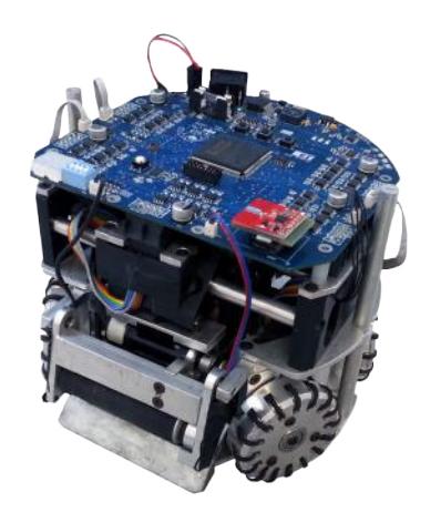
For the RoboCup 2018, the RoboFEI team intends to use the same electronics and mechanical design that have been used over the last years, as shown in figure 1, but we also intend to use the new robot design that we are developing since 2017, playing with a mixed team. The new version is in the test phase, but significant modifications have already been made to follow the challenges and the evolution of the league. We decided to start the software strategy from scratch, because some implementations of artificial intelligence's algorithms wouldn't be possible in the old architecture. We have already done some tests in the XV Latin American Robotics Competition (LARC) [1] and the new software features provided satisfactory results. This new project is focused in high performance, modular design and easy maintenance. With our researches, we hope to bring innovations and new ideas for the community.
Electronic Design
Since RoboCup 2014, RoboFEI's team released the current electronic design as open source to the community. All the schematics, layouts and firmware are available on-line, under a Creative Commons license, in RoboFEI's web-site (www.fei.edu.br/robofei). Currently, the electronic hardware remains the same update of last year, the components description are shown in table 1.
Current Electronic Description.
| Device | Description |
|---|---|
| Main Board | CPU: Xilinx Spartan 3 FPGA operated with 50 MHz clock |
| MOSFET Driver | TC4427 working with IRF7389 MOSFET |
| Current Sensor | ACS712 with A/D converter AD7928 |
| Kick Board | Boost converter topology. |
| Kick Storage | Two capacitors of 2700 µF, in parallel, charging up to 160V in 16s. |
| Kick MOSFET | IRFSL427, Id 72A DC. |
| Driving Motor | Maxon,EC-flat-45 50W with hall sensor. |
| Dribbling Motor | Maxon EC-max-22 25W with hall sensor. |
| Ball Sensor | TEFT4300 infra-red emission diode and photo diode pair. |
| Communication | nRF24L01 transceiver, 2 Mbps, 2.4/2.5 GHz. |
| Power Supply | LiPo, 3-cells (11.1V ) and 2250 mAh capacity. |
Electronic Design in development
To follow the modifications and challenges proposed by the Small Size League for the next few years, the electronic system is being renewed in its hardware and firmware configurations, the new topologies of the circuits are in the test phase. The old design have characteristics that are making some maintenance impossible, the creation of new functions is difficult and the evolution of the team has been slow, because all the circuits are welded directly on the main board, our current radio system can't control more than 8 robots simultaneously and the CPU's storage memory is full. The last revision was made in 2012, the topologies are obsolete, generating exhausting maintenance and many expenses with the purchase of components, because some of them always burns or have their manufacturing discontinued. The new version of the project will correct the major problems of the previous design, will replace the components by more modern and more efficient models and the circuits will be mounted on separate boards, making the design modular and ensuring the quickly replacement of defective boards during the competitions.
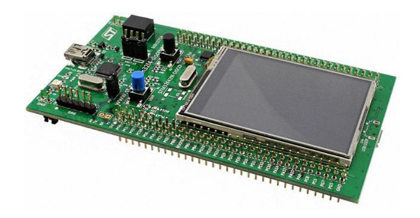
The main change will be in the CPU of the electronic system. We chose the STM32F429ZIT6 microcontroller, from ST Microelectronics [2], because it is simple to program, has low power consumption and is composed of several special peripherals very useful for our application, such as, Timer, Interrupts, UART, SPI and others. In the first place, we will use a Discovery Board, that shown in figure 2, because it is the easiest way to start developing and already has a touch screen display added, where we can configure and change the parameters of the robots quickly using the graphic interface. To reduce CPU processing and increase the accuracy of the motor control, a specialized chip will be used for this application, the A3938 3-Phase BLDC Controller IC, from Allegro Microsystems [3].
In the power electronics department, we have studied several topologies of DC-DC converters such as SEPIC and Flyback [4] to design a new kicking device since 2015. After those studies, the Flyback circuit stood out as the best option for our purposes of optimizing our kicking system besides downsizing maintenance time. For this goal, we chose the LT3751, from Linear Technology [5], that is a controller specifically designed for this topology. Since then, we had to stop our studies to adapt our current kicking board to the angular kick that we developed last year. The new system will be adapted to this type of kick, delivering this technology to all of our robots. Recently we are testing the efficiency of the circuit in prototypes and planning to get the first version of the new kicking board by the middle of 2018.
Mechanical Design
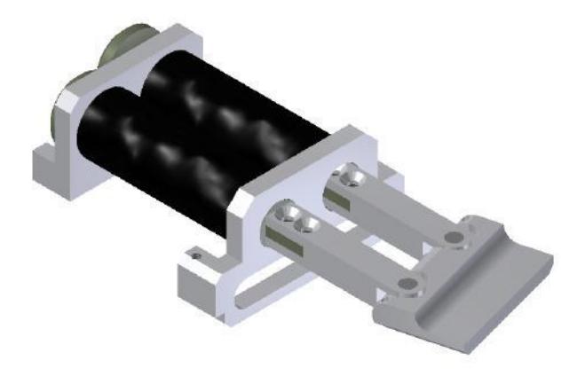
The mechanical design is basically the same of previous years, however studies are being done to build a new structure in purpose to have more robots. Our goal is to participate in next years in division A. This new project is focused on modular design and easy maintenance. We are studying the possibility to have the solenoids with same geometry. Our robots have two kinds of solenoids, one for straight kick that use cylindrical geometry and another one which uses a flat geometry for chip kick. The idea is to use three solenoids of the same dimensions. Two of them for the directional kick and another for the kick chip, this pattern would simplify the production and reduce costs. We are continuously studying the mechanism that could be able to vary the direction which the ball is launched who was presented in the last TDP [6]. Figure 3 We evaluate the efficiency at RoboCup 2017 with some directional kicks, however the results didn't go as expect.
There's still a concern to implement this kick in the game's strategy since it was only a prototype. It was possible to obtain the relation between the trigger time of each solenoid's plunger with the angle that the ball will be launched from the kick plate. It was acquired through the finite element method with dynamics simulations. The equation is shown below, where the angles were obtained in degrees and the time in milliseconds. The mechanism has a geometry limitation that we can work within a range of 20 degrees variation to each side, so we know that the maximum time of triggering between each solenoid's plunger is 2,5 milliseconds.
$$\theta = 7,2907\Delta t$$
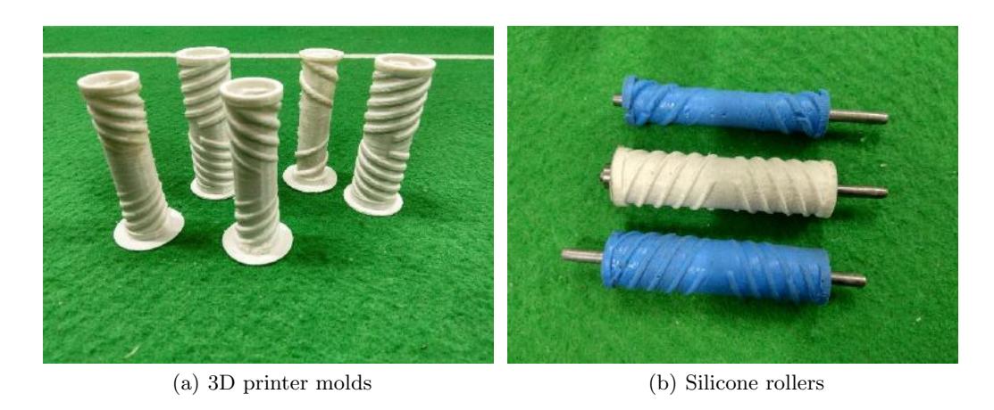
We are also working on the dribbling device that uses the inverted pendulum concept where the damping is provided by a viscoelastic foam, presented in the TDP of 2015 [7]. Our aim is performing the kick that can describe a curved trajectory as presented in the last RoboCup by the OP-AmP team [8]. For this purpose, some modifications were necessary in this device. Currently the roller is composed of polyurethane (PU) of hardness 30 Shore A of smooth cylindrical format. In order to centralize the ball were made threads in roller. Several geometries with various types of threads and pitch were tested. The new roller is made of silicone and has a hardness of 20 Shore A. They were cast in ABS using a 3D printer molds, as shown below in figure 4. Another modification required was the transmission ratio of the motor dribbler (Maxon EC-Max 22 25W). So the ball could perform a curve trajectory, a high rotation was required. To solve this, we changed the transmission ratio from 1:3 to 1:1. Using the maximum power of the motor we reached a rotation of 8820 rpm, however, there are friction losses in the belt. We are still working on the efficiency of this mechanism to get more accurate kick.
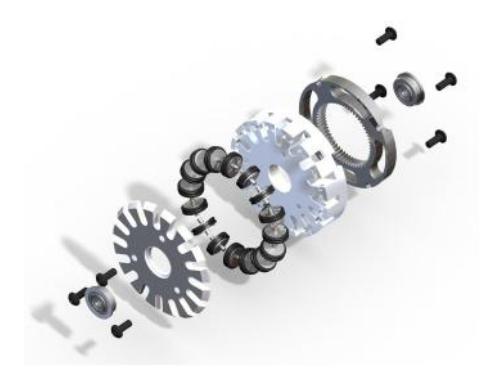
This year a small change was made to the wheels, we are now using o-rings instead of the old quad-rings. The change was made due to the difficulty of obtaining the quad-rings and their expensive price. The exchange was validated in the games during the last competition. We are developing new omni-directional wheels, the current wheel version has been used since 2012. Figure 5. To improve the wheels, we intend to modify the fluidity of the movement, decrease their size, decrease their weight and facilitate their machining. For this, the structure of the wheel will be remodelled to grow the number of o-rings. The reduction in the wheel's size is due to the interest in increasing the available space in front of the robot. Several prototypes have already been made, but still subject to testing to evaluate the best model.
Software Development
Old Software erased
As you may notice, for this year's RoboCup, major changes are being made by our team in all parts of the project. We are leaving behind great part of our old software and taking some parts that still can be reused. Some of the the problems that we've faced along the past years are: different programming styles, which ended up making the code messy and lack of modulation and documentation; bad programming manners.
New Software in development
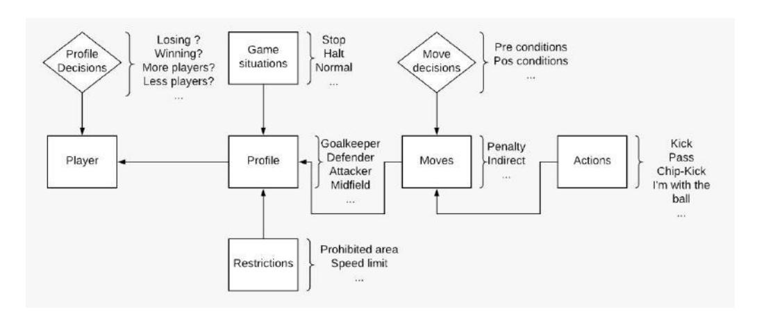
We are developing a new software architecture. An illustration of the new structure can be seen in figure 6, where now everything is written in its own block and the basics functions are already done (for example: pass, walk, kick, etc.), some others are in development. Some of the new and most important improvements we achieved are:
- Protocol Changes: we had modified the radio protocol, so that we could access/change functions to our new robot that we couldn't before. Simple changes into the radio package allowed us to use the roller and trigger the solenoid simultaneously.
- Firmware: not only the software strategy, but also part of the firmware is being remade. With that and reviewing the software architecture we could reach new levels, so our future robot could make the most of the interaction low level/high level.
Beyond that, both receipt and treatment of SSL Vision and SSL Referee is already working, it is interesting to note that given the new software structure now we have the possibility of running tests using grSim [9] , something that was impossible to do using the old software. We are now able to make great changes that we couldn't make before, and although progressing slowly, we are achieving a satisfying success in our journey. We've made quite a lot, but we are still in the beginning. Some of the stuff we are working into, and intend to make are: making a better and more participating goalkeeper, a new defence strategy due to the new rectangular defence area and create a new interface with all the robot's informations and statistics.
Path-Planning Algorithm
In the new software it is being used the A* (A star) algorithm for path-planning as described at [10]. In order to use this algorithm it was necessary to create a grid representation of the field, it contains all objects in the field, such as, ally robots, opponents robots and the ball. The grid is treated as a two dimensional matrix. Given the dimensions of the actual field it isn't practical to use a 1 : 1 scale, because of that it was necessary to create the grid in a reduced scale, an effect of this is a minor reduction in precision when generating a path, fortunately, this loss of precision did not cause any noticeable impact when testing in a real size field. Even though we are able to significantly reduce the matrix size and processing time to analyse, it still can have a large memory usage and processing cost, to avoid that it was used a protocol to storage and identify the objects on the grid. Using this strategy it is possible to use a few bytes to inform everything needed to use the path-planning algorithm, the protocol uses only one byte per cell and the information in each cell can be seen in table 2.
The lower nibble contains the robot ID, where, bit 0 is the less significant and bit 3 is the most significant. The fifth and fourth bits represent the type of the object that occupy a cell, the values defined to each object can be seen in table 3. The sixth bit is used to inform which cell is the upper left corner of the robot, this information is used to create the graphical representation of the robots. The seventh bit indicates if the cell is occupied.
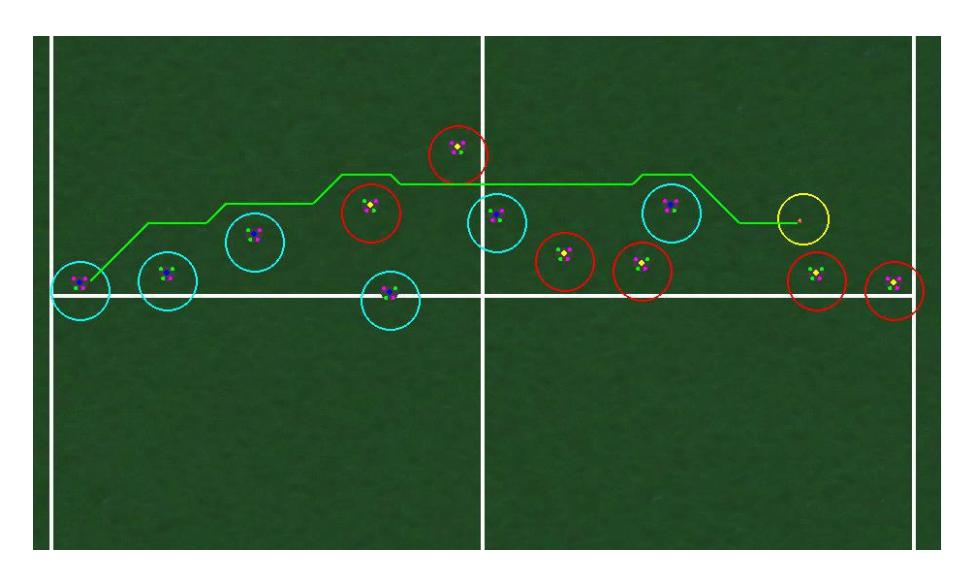
Also, to avoid any collision it is defined a safety region around every object in the grid. Figure 7 shows an example of the algorithm working, the green line is the calculated path to get the robot to its destiny, in this case, the ball, which is inside the yellow circle. Opponents are marked as red circles.
Protocol used in the grid.
| Bit | 7 | 6 | 5 | 4 | 3 | 2 | 1 | 0 |
|---|---|---|---|---|---|---|---|---|
| Meaning | State | First cell Type Type | ID | ID ID | ID | |||
| Description | Occupied cell = 0 | Robot ID | Robot ID | |||||
| Empty cell = 1 | MSB | LSB |
Values for each type of object in the grid.
| Type | 5 | 4 |
|---|---|---|
| Opponent | 0 | 0 |
| Ally | 0 | 1 |
| Ball | 1 | 0 |
Acknowledgements
We would like to thank, in advance, the Small Size League Committee, for the consideration of our material. We would like also to immensely thank the staff of Centro Universit´ario da FEI, for all the help we always received.
References
- LARC, Latin American Robotics Competition (http://www.cbrobotica.org). 2017.
- STM32F429ZIT6 datasheet, ARM Cortex-M4 32b MCU+FPU, 225DMIPS, up to 2MB Flash/256+4KB RAM, USB OTG HS/FS, Ethernet, 17 TIMs, 3 ADCs, 20 comm. interfaces, camera and LCD-TFT STMicroelectronics. (www.st.com), 2016.
- A4915 datasheet, Three-Phase Power MOSFET Controller. Allegro Microsystem Inc., 2015.
- Documentation, High Performance DC/DC Controllers. Linear Technology Corporation. (www.linear.com), 2015.
- LT3751 datasheet, high voltage capacitor charger controller with regulation. Linear Technology Corporation. (www.linear.com), 2016.
- Danilo Pucci, Caio B. Jos´e, Andr´e O. da Silva, Filippe O. A. Chaves, Guilherme P. de Oliveira, Vin´ıcius M. Alves, Lucas Carlos dos Santos, Lucas A. da Silva, Abner R. Santos, Danilo R. Vassoler, Iago A. Martins, Victor D. de Almeida, Marcos A. P. Laureano, Reinaldo A. C. Bianchi, and Flavio Tonidandel. RoboFEI 2017 Team Description Paper. 2017.
- Danilo Pucci, Fernando Rodrigues Jr., Caio Schunk, Caio Braga Jos´e, Victor Torres, Thiago Silva, Victor Amaral, Andr´e De Oliveira Da Silva, Jos´e Angelo Gurzoni Jr., Reinaldo A. C. Bianchi, and Flavio Tonidandel. RoboFEI 2015 Team Description Paper. 2015.
- Takamichi Yoshimoto, Takato Horii, Shoma Mizutani, Yasuyuki Iwauchi, Yutaka Yamada, Kousei Baba, and Shota Zenji. OP-AmP 2017 Team Description Paper. 2017.
- Monajjemi V., Koochakzadeh A., Ghidary S.S. (2012) grSim, RoboCup Small Size Robot Soccer Simulator. In: R¨ofer T., Mayer N.M., Savage J., Saranl U. (eds) RoboCup 2011: Robot Soccer World Cup XV. RoboCup 2011. Lecture Notes in Computer Science, vol 7416. Springer, Berlin, Heidelberg.
- Choset, H.,Robotic Motion Planning: A* and D* Search. Available at: (www.cs.cmu.edu).