RoboIME: From the top of Latin America to RoboCup 2018
Carla S. Cosenza, Gustavo C. K. Couto, Lucas Germano, Lucas G. Corrêa, Luciano de S. Barreira, Luis D. P. de Farias, Luis R. L. Rodrigues, João G. O. C. de Melo, Matheus Bozza, Matheus P. de Souza, Nicolas S. M. M. de Oliveira, Onias C. B. Silveira, Rebeca P. dos Reis, Renan P. de Souza, Sergio G. S. Dias, Yugo Nihari, Paulo F. F. Rosa
Instituto Militar de Engenharia, Rio de Janeiro, Brasil
Abstract This paper describes the electronic, mechanical and software designs developed by the RoboIME Team in order to join the RoboCup 2018. The overall concepts are in agreement with the rules of Small Size League 2018. This is the fifth time RoboIME participates in the RoboCup.
1 Introduction
RoboIME is a Small-Size team from the Instituto Militar de Engenharia, IME, located in Rio de Janeiro, Brazil. This is the ninth time the team takes part in competitions, being the best result first place in the Latin American Robotics' Competition 2017, two second places in RoboCup Brazil Open 2011 and in Latin American Robotics Competition 2012.
All students that work in the SSL project are members of the Laboratory of Robotics and Computational Intelligence at IME. Team's previous works were used as reference [2] [3] [1], as well as the help from former members of the team as consultants and tutors.
This article describes the team's general information and improvement in the most recent semester, since our previous TDPs for RoboCup 2017 have detailed explanations on our previous changes. This article is organized as follows: software in section 2, embedded eletronics in section 3 and mechanical design in section 4. Conclusions and future works are discussed in section 5.
2 Software Project
This paper reports the main improvements and changes since 2017 RoboCup project.
2.1 Passing State
One of the big changes of the software project was the introduction of a passing state that is used in the indirect and direct kicks. When this state happens the striker takes its position using the Inverse Best-y, described in section 2.1. The attacker waits for the striker arrive in its position to execute the pass. Then the striker tries to intercept the ball. When the ball is near the striker, touches a robot or goes out of the field, the personalities can change and therefore the striker becomes the attacker (see the dynamic personalities in [3]).
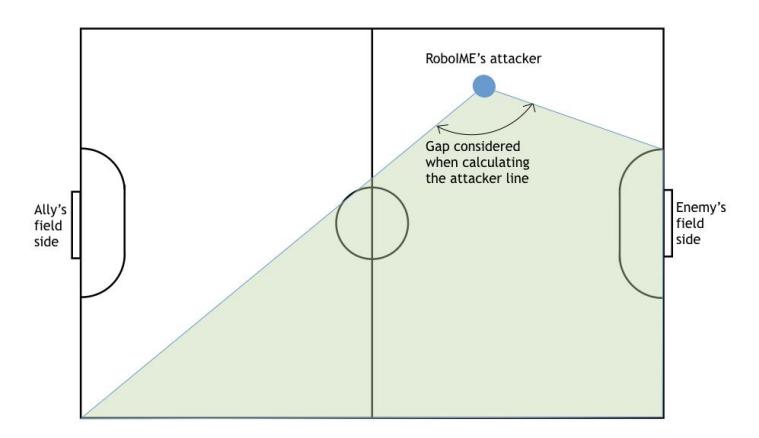
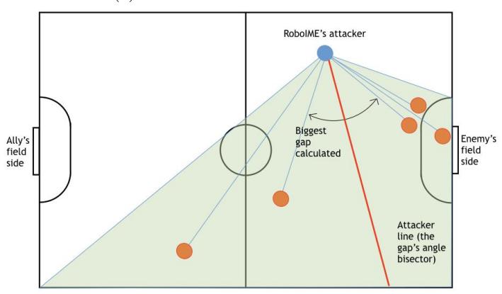
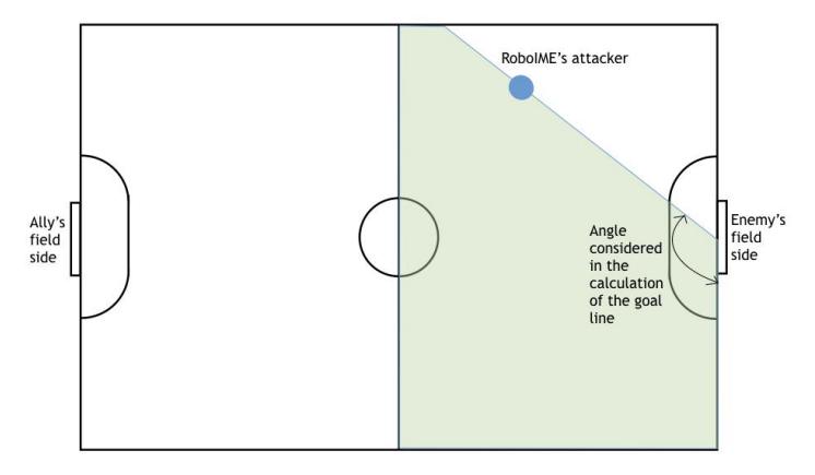
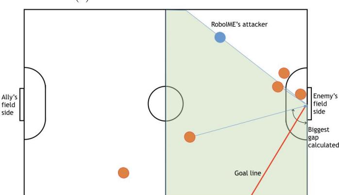
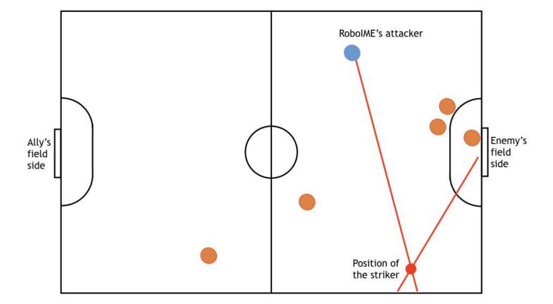
Inverse Best-y: The inverse best-y calculates the best position for the striker to receive the pass. In order to do that, the intersection of the attacker line and the goal line are calculated. The attacker line is the line that contains the position of the attacker and whose slope is the tangent of the angle bisector of the biggest gap of robots. This angle is calculated from the beginning of the defense area to the opposite lower corner of the field (see figure 1). This line gives the best direction in which the attacker can kick the ball. The goal line is the line that contains the center of the goal and whose slope is the tangent of the bisector of the biggest gap of robots, calculated from the attacker and the corner on the opposite side of the striker and close to the enemy's side (see figure 2). For the calculation of this line, robots on the ally field side are not considered. This line gives the best direction in which the striker can kick the ball without any interference. The intersection of the two lines will give a point with a free path from the attacker and a free path to the goal, which is essentially the objective of the pass (see figure 3).
2.2 Personalities
For the advancement of the AI, some changes were made to the personalities (see Personalities in [3] in order to have a better understanding on how the personalities work).
- Attacker: Now, when an enemy robot has the ball possession and it is located at the ally side of the field, the attacker's target point is set at the position of this robot. This offensive behaviour enables a dispute for the ball possession, since the two of them will stay face to face trying to kick the ball to the other side.
- Defender: When an enemy with possession of the ball approaches the wall of robots, one of the defenders also assumes the same offensive behavior as described in the attacker's item, in order to kick the ball away from the ally's goal.
- Goalie: The change in the goalie is that the radius of the semicircle it follows is bigger, allowing it to protect a bigger area of the goal.
- Striker: The striker now assumes a man-marking behavior when an enemy robot has the ball possession, which is determined by whether the ball is closest to an ally or enemy. First, it is calculated for each enemy robot its distance from the ally's goal and from the robot which has ball control. The one which presents the smallest addition of these two results is considered the most dangerous enemy. Then, it is applied the GoTo method to position the striker properly between the enemy which has the ball and the most dangerous one. This position is set next to this last robot mentioned, along the vector that links these two enemies. The striker is oriented in order to kick the ball away from the man-marked robot, in case the most dangerous one receives a pass from the other.
2.3 Test Module
In order to help test infield and during the timeouts, the test module was developed. There are three major testing modules, as described as follows:
- Kick Test: The Kick Test is used to test the kick with controlled magnitude. It is possible to generate a log with kicking performance data (such as ball positions and the kick's magnitude in each observable moment of the test), which is useful for calibrating the kick for passing.
- Dribbler Test: Used for turning the dribbler on.
- Control Test: The Control Test works by setting a sequence of waypoint coordinates, creating a circuit and making a robot perform it. Even being this simple, it was the best improvement observed for testing, since it allows any robot movement impairing issues be quickly detected.
2.4 Control
Obstacle Avoidance In order to avoid collision with other robots, the Potential Field algorithm is used (further reading can be found at [4]). For every ally robot, it is computed the other robots' influence described by the potential field model. Furthermore, the ally robot's velocities are hence updated. Even though this algorithm doesn't guarantee the robot won't be trapped in a local minimum, it is simple to implement and it has been shown to be an efficient approach for obstacle avoidance in highly dynamic environments. In order to achieve an optimized trajectory and to avoid problems that may occur with the Potential Field approach, a rapidly exploring random tree (RRT) based algorithm is currently being developed for critical roles, such as the attacker and the striker.
3 Electronics Project
Since the RoboCup 2017, a lot of effort has been put into making the electronic project more robust. Standardizing the production of the boards proved to be an improvement in the board's reliability. Also, the modularization of the project proved once again to be useful, enabling to remove a defective robot mid-game, debug it, and put it back in action within a few minutes. The LARC 2017 competition was very useful to test the changes in the project.
3.1 Firmware
The firmware was improved from a bare metal code that ran with hardware interruptions to execute the communication and the wheel controls, to a real time operating system. FreeRTOS was chosen due to its ample support in online community and its robustness.
Previously, the firmware in the transmitter was the same as the one in the robots, being the connection to a serial port the trigger to call some functions instead of others. This was also changed with the addition of the FreeRTOS tasks, in order to make the code clearer and more readable.
With such architecture, new additions to the code are easier to make, not having to know the whole flow of the code, just the particular module being modified.
The transmitter's firmware consists of two main tasks, responsible for reading the USB COM port and transmitting its commands through the NRF24l01P and the other responsible for reading and writing in the command line for debugging purposes.
The robot's firmware has a task for receiving the commands from the transmitter, another for controlling the four wheels' speeds, a third for activating the kicks and check for the ball sensor and a fourth for transmitting back data for the software.
Kick Strength One major contribution of the LARC 2017 was the kick strength modelling. After several tests using the camera system and controlling the time the capacitor discharges in the coil, the data was collected and it was possible to develop a simple equation that, with the time the capacitor discharges, estimates the ball's speed.
Robot Communication One big improvement from RoboCup 2017's project to RoboCup 2018's is the addition of communication from the robots to the AI software. Previously, due to difficulties in the firmware configuration and hardware limitations, information from the robots could not be transmitted to the AI. For example, if the ball sensor is activated or not or even if it is working. With such limitation fixed, this forward-backward communication becomes possible, enabling more possibilities for the IA system.
3.2 Control
Maintaining the robot at the expected speed or position is very important so that the software project is able to work properly. To try to keep the robots moving as expected, there are several routines to check or filter the results obtained from the vision system and the robots themselves.
Dealing with a non-ideal movement In cooperation with the each wheel's speed being controlled, it is important to control the overall direction that the robot follows. Wheels accelerate differently from each other. One wheel achieving the final speed before the others can compromise the entire movement of the robot, changing its direction due to the robot's rotation. Incremental acceleration of the robot with the slower one acting as the leader is a possible solution to this problem, therefore acceleration should be sacrificed over overall trajectory precision.
3.3 Board Designs
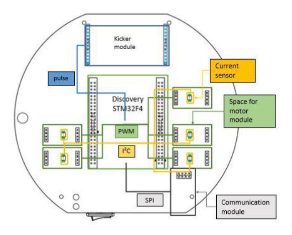
RoboIME's hardware platform kept its same structure, as seen in figure 4.
The motor module remained unchanged since the last competition, proving itself to be very reliable, with only few remaining problems during the games, either in the RoboCup or LARC.
Stamp module This module is responsible for performing all the logical functions, serving as a brain for the electronic system. The module is a commercially available board - the STM32F4-Discovery; it is a development kit that aggregates an Arm Cortex M4 microcontroller with a series of peripherals like a debugger, a motion sensor, two push buttons and two USB plugs.
This year STM electronics changed the main microcontroller in STM32F4- Discovery kit from the the STM32F407VGT6 to the STM32F411VET6, that will obligate some changes in timers configuration due to differences between them.
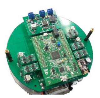
Main Board The Main Board, figure 5, provides physical support to the other modules and connection between them and the robot's actuators, sensors and battery. Most of the main board is composed of simple routes and planes making these connections. But it also implements some important circuits:
Firstly, the protective and regulation circuit that uses a tank capacitor and a resettable fuse to limit and to regulate the power delivered to each motor module. The circuit also implements the INA220, a current sensor that reads the current delivered to each motor module and communicates with the stamp board using I2C. Secondly, the simple circuit transforms the two cell lithium polymer battery voltage into 5V in order to feed the stamp board. It also allows the battery voltage to be read by the stamp board using the sensor class.
The design of this board was also improved for the LARC 2017. The throughhole capacitors and simple fuses were substituted by SMD capacitors and modern SMD resettable fuses. The power routes were changed to planes, and the INA220 was added to make it possible for the stamp board to control the current delivered to each motor module.
Kicker module This module stores power in two electrolytic capacitors of 2200µF, 200V using a DC-DC step-up circuit controlled by the MC34063 IC, that transforms the 7/8V DC of the battery supply into a 180V DC power supply to charge the capacitors. It also uses two IRFP4868PBF Power MOSFETs driven by an IR4427 Mosfet driver to close the high voltage circuit, that releases the power stored in the capacitors to one of the coils. The stamp board can also control the kick speed, controlling the signal duration sent to the mosfet driver.
Besides, a problem concerning the switching of the IRFP4868PBF, was corrected by running simulations. Through that tool, it was possible to determine the cause of some failures on switching and correct it with an improved design. By adding a boost circuit capable of turning the 7V battery voltage to 12-15V, which is a more efficient switching voltage.
4 Mechanical Project
The mechanical project still is developed using CAD (Computer Aided Design) and CAM (Computer Aided Manufacturing) softwares. Therefore, the team members are involved on the conception but also on the machining itself. CNC milling, CNC lathe and 3D printing were used for the manufacturing of the new parts.
The participation in the RoboCup 2017 in Japan made it possible to notice many opportunities of improvements of the mechanical project, not only because of the real experience of the matches but also because of the exchange of information with other teams. Next, it will be described the improvements made since the competition at Nagoya and also the planning for the RoboCup 2018.
4.1 Wheels transmission system
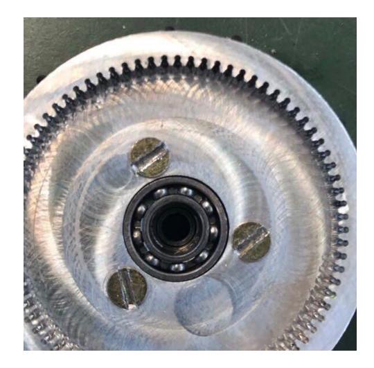
One of the major issues that occurred during RoboCup 2017 happened on the wheels transmission system. The gear utilized to transmit movement from the engines to the wheels was made through 3D printing by a stereolithographic process. However, the resin was not strong enough; and, match after match, it was noticed the wear of the gears teeth until the moment when the movement was not transmitted at all. The machining difficulty was due to the distance between consecutive teeth being less than 1mm. Despite that, it was possible to machine it by combining the use of a 0.6mm diameter drill and a 1mm diameter end mill (see figure 6). The new gears were used on LARC 2017 and did not present any problems.
4.2 Wheels components machined with aluminum
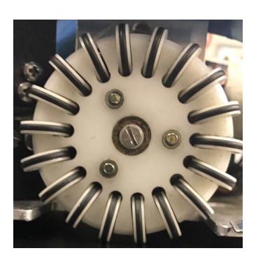
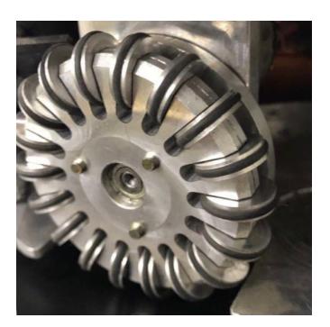
The omni-directional wheels are composed of 18 small wheels perpendicularly coupled around a bigger wheel. The robot's wheels utilized during RoboCup 2017 were composed of plastic components. In order to improve the precision of the movement and cease warping problems, new parts were machined in aluminum: the small wheels, as well as the internal and external parts of the bigger wheel. Figure 7 shows the difference between the old and the new wheels.
4.3 Dribbler
The dribbler is composed of an engine, a transmission system, a roller that makes the ball dribble, and it lateral mounting, named dribble arms.
Dribble arms The dribble arms used at RoboCup 2017 were made by 3D printing with ABS plastic. Due to the impacts with the ball and with other robots, the components would eventually break or the LEDs and sensors placed inside the arms would get damaged, since the plastic presented some malleability. Having that in mind, it was noticed the necessity of changing the material of these parts from plastic to aluminum. The machining of the aluminum dribbler arms was made through CNC milling. Also, each arm, which was composed of two parts, was simplified to one part, in order to make the manufacturing process easier.
Another observed problem was that the low kick would impact the ball only if it was well positioned. However, during a game this was not so usual. Consequently many kicks were not made. The solution to this issue involved the backward positioning of the whole dribbler system, which increased the chances of impact of the low kick with the ball, even when the ball was not at the best position.
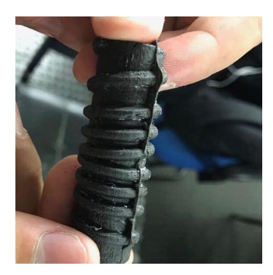
Roller For the 2018 RoboCup a new roller utilizing silicon rubber was developed. The manufacturing process started with 3D printing a plastic mold. After that, the mold was filled with silicon rubber in liquid state. The addition of catalyzer solidified the material after a few hours inside the mold. The roller design includes two helical cavities that make the ball go to the center when it spins, optimizing the ball possession (see figure 8).
4.4 Kick sensor protector
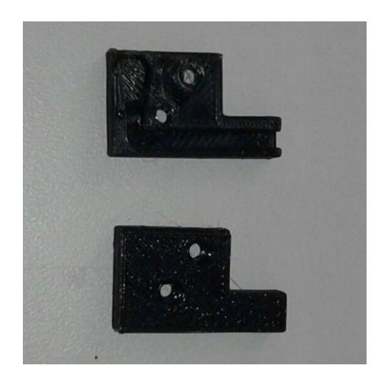
The sensor and LEDs failure occurred not only due to the ABS plastic malleability, but also because they were laterally exposed to impacts, which could damage the wire terminations. The developed solution consisted on a lateral protector with a cavity for placing the wires, protecting them from direct impacts. On LARC 2017, 3D printed protectors were utilized, made with ABS plastic (see figure 9). Both the LEDs and sensors have shown no any mechanical damage after the competition. Therefore, machining the protectors on aluminum are not a priority for RoboCup 2018, although this still is a possibility to increase the hardiness of the robots.
4.5 Mechanism for fast removal of the cover
RoboCup 2017 proved that our solution for the cover for the robots was far from good. Two screws were used, which took more time than acceptable to remove, even using an electric screwdriver. During a match, this made it harder to release and to connect the batteries and to perform eventual repairs of mechanical and electronic parts.
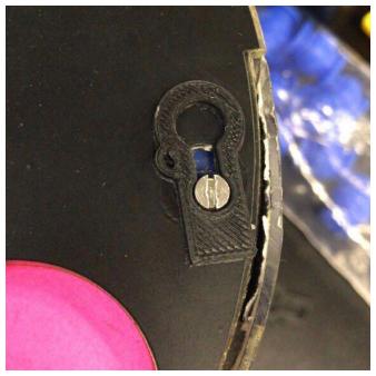
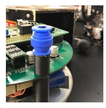
To solve this problem, a mechanism that made it possible to fasten and remove the robots cover quickly and without the need of any tools was developed. This mechanism consists of a spring concentrical with each of the two supportive rods pushing the cover upward. At the same time, a lock placed above the cover blocks the free upward movement (see figure 10 A). Therefore, to remove the cover it is only necessary to push it down and to move the two locks, freeing the upward movement. For the sake of simplicity, the spring effect was achieved by using rubber gimbals (see figure 10 B).
4.6 Planning for RoboCup 2018
Until the RoboCup 2018, the mechanical project might face some more modifications. Three improvements are already being elaborated in order to make the functioning of the robots more stable and reliable.
New kick system With the experience exchanged with other teams, it was realized that the kick system is not efficient. The possibility of reducing the solenoid's dimensions by changing the cooper wire thickness, the solenoid's diameter and the number of windings is being analyzed in order to improve it.
Transmission system of the dribble An o-ring has been used to transmit movement from the engine to the roller. However, it was noticeable that slipage occurs between the pulley and the o-ring, when the ball is being dribbled.
Therefore, there will be changes made on the transmission system to use gears instead of an o-ring.
New covers The current covers make it possible to observe the electronic components only through the front of the robot. Thus, during the manufacturing of new covers, that will be taken into account in order to make it possible to see all the LEDs from the electronic board, despite the angle at which the robot is on the field. Also, a lateral access will be made to allow a faster battery change during the matches.
5 Conclusions
For the this competition, we are aiming into continuing the progress established last year: experimenting a new approach to the software project, modularizing the electrical project and producing more reliable CADs and CAMs in the mechanical project.
5.1 Acknowledgement
This research was partially supported by the Army's Department of Science and Technology (DCT), Fundação Carlos Chagas Filho de Amparo à Pesquisa do Estado do Rio de Janeiro - FAPERJ(grant E-26/111.362/2012); Fundação Ricardo Franco (FRF), Fábrica de Material de Comunicação e Eletrônica (FMCE/IMBEL) and the companies Altium, SKA and National Instruments. The team also acknowledges the assistance of Clara Luz de S. Santos and Jorge L. de Castilho Jr from FMCE. Special thanks to all former members of RoboIME. Without their support, this team would not be here.
References
- Jan L. L. Segre Lucas O. de Lima Naum A. F. Barreira Victor Bramigk Gustavo C. K. Couto Renan P. Souza Luis D. P. Farias Onias C. B. Silveira Rebeca C. Brito Carlos A. D. Pinto Johnathan F. Rosa Paulo F. F. Rosa. Roboime: on the road to robocup 2016. pages 1–9. Available at https://github.com/roboime/roboime-tdp.
- Carla S. Cosenza Gustavo C. K. Couto Luciano de S. Barreira Luis D. P. Farias Luis R. L. Rodrigues Jan L. L. Segre Matheus C. Castro Nicolas S. M. M. de Oliveira Onias C. B. Silveira Renan P. de Souza Victor Bramigk Yugo Nihari Paulo F. F. Rosa. Roboime: on the road to robocup 2017. pages 1–12. Available at https://github.com/roboime/roboime-tdp.
- Carla S. Cosenza Gustavo C. K. Couto Luciano de S. Barreira Luis D. P. Farias Luis R. L. Rodrigues Jan L. L. Segre Matheus C. Castro Nicolas S. M. M. de Oliveira Onias C. B. Silveira Renan P. de Souza Victor Bramigk Yugo Nihari Paulo F. F. Rosa. Roboime: Team description paper. pages 1–6. Available at https://github.com/roboime/roboime-tdp.
- Ramon Jansen. Waypoint navigation with obstacle avoidance for mav's. RAM, Robotics and Mechatronics, pages 1–7, 2016. Available at https://www.ram.ewi.utwente.nl/aigaion/attachments/single/1338.