UMass MinuteBots 2018 Team Description Paper
Kyle Vedder, Edward Schneeweiss, Sadegh Rabiee, Samer Nashed, Spencer Lane, Jarrett Holtz, Joydeep Biswas, David Balaban
University of Massachusetts Amherst, Amherst MA 01003, USA
Abstract This paper presents the changes in electromechanical design and a selection of the algorithms used by the UMass MinuteBots, a second-year RoboCup team from the University of Massachusetts Amherst. The team uses RoboCup as a research application area for both hardware and algorithms. We are actively researching many areas, including multi-agent kino-dynamic navigation, time-optimal control, system identification, and failure recovery. As a second-year team, our primary objectives for the 2018 RoboCup competition are to solidify basic soccer capabilities, develop more robust advanced tactics, and apply current state-of-the-art research whenever possible. As winners of the lower bracket in the 2017 competition, we expect to continue to improve and play competitively against all teams.
1 Introduction
The UMass MinuteBots were founded at the University of Massachusetts Amherst in 2017. We are associated with the Autonomous Mobile Robotics Laboratory in the College of Information and Computer Sciences. RoboCup is a research platform for our lab, we believe excellence on the field will follow from excellence in our research. Thus, our goal is to have a successful RobCup campaign driven by an application of novel, state-of-the-art research. Research foci include time-optimal control, joint kino-dynamic planning in adversarial domains, system identification, and failure recovery. As a new team, much of our work has involved reproducing existing algorithms from the literature however, we are working on integrating our research into our RoboCup system.
This team description paper primarily discusses the modifications to our existing system that we are making for RoboCup 2018. A more comprehensive description of our hardware and system architecture can be found in our 2017 TDP [1]. In Section 2, we first present our hardware updates for the MinuteBots robots. Next, in Section 3, we present our approach to navigation and motion control. We then discuss two of our additional research areas, specifically system identification in Section 4 and semi-automated repair of robot state machines in Section 5. Finally, we analyze our performance from the 2017 RoboCup, and present both our short-term and long-term research goals in the RoboCup domain.
2 Hardware
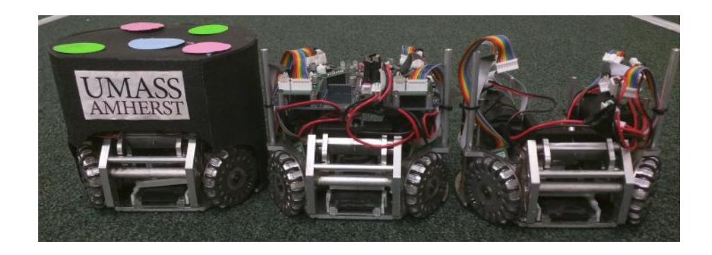
In 2017, we completed the design and construction of our first generation of SSL Robots. Our focus last year was on simplicity, durability, and ease of maintenance. Of particular note is our modular electronics system in which there is one main board and several driver boards. The main board integrates radio receiving, processing, and power distribution while the drivers control individual components such as the motors or the kicker. Our completed hardware is shown in Fig. 1. Additional detail about our electromechanical design can be found in our 2017 TDP [1].
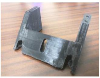
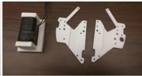
Since the 2017 competition, we have begun construction of two additional robots and have made a few modifications to our design. In particular, we are redesigning the dribbling and kicking mechanisms. We are also experimenting with 3D printed parts to reduce weight and manufacturing costs. The dribbler backstop was 3D printed and included on the 2017 robots. This is shown in Fig. 2a. We have also printed a piece of our kicking mechanism and a portion of our support structure which are shown in Fig. 2b. We experimenting with replacing other aluminum parts with plastic, 3D printed versions, and hope to integrate them into our robots for the 2018 competition.
3 Navigation and Motion Control
We have identified navigation, motion control and safety to be three critical low-level behaviors in the RoboCup domain. We believe making these three behaviors robust and accurate is critical to fielding a competitive team. We also have ongoing research in these areas.
For our navigation planning, we switched to planning on an eight-connected grid. We found searching this eight-connected grid to be very fast using an exact heuristic: the octile distance. As obstacle collision checks dominate the runtime of eight-connected grid planners and many other roadmap based real-time planners, developing strategies to limit this work is important to meeting our real-time requirements. For eight-connected grids, we can algorithmically calculate the eight-connected grid vertices potentially in collision with an obstacle on an obstacle by obstacle basis, and arbitrarily combine these invalidated obstacle collision lists together to form a full list of invalid vertices for each robot. This avoids the very expensive overhead of computing invalid vertices on a robot by robot basis. This is particularly useful in situations where an obstacle is only applied to one robot. For example, the free kick taker is allowed within 500 mm of the ball and other robots are not.
In addition, we are experimenting with path collision repair on eight-connected grids. Detecting and repairing future collisions in individually planned paths is important as without it we end up relying upon Dynamic Safety Search (DSS) [2] to prevent collisions between our own robots. This is a computationally expensive process and often leads to highly suboptimal paths.
For motion control, we use two different control systems: Near Time Optimal Controller (NTOC) [3] and Two Stage Optimal Control Solver (TSOCS). Both NTOC and TSOCS were in use during the 2017 competition, though we have been improving TSOCS and its associated uses since the competition. NTOC solves the problem of arriving at a target configuration at rest with an arbitrary start configuration and velocity. TSOCS is used to solve problems with arbitrary start and end velocity and with bounded acceleration and unbounded velocity. We use TSOCS for situations requiring quick action such as ball interception and NTOC as our default control strategy.
As mentioned above, we continue to utilize DSS as the last step of our planning and control loop to help prevent any potential crashes. More information on DSS can be found in the original paper [2].
4 System Identification and State Estimation
There exists remarkable amount of nonlinearity in the dynamics of the soccer robots, which stems from various factors such as, the motors' dynamics, the differences in the wheels, as well as the wheels' slippage. These nonlinearities become specifically important at large acceleration and velocity magnitudes. Moreover, each robot also behaves differently from the others due to mismatches between their parts. Therefore, one simple kinematic model would not be able to compensate for the nonlinearities in the dynamics of the robots and cannot address the differences between robots' dynamics either. Hence, it would result in poor control and trajectory tracking.
In order to address this problem, we train robot specific kinematic models. The models are in the form $v = f(u)$, where $v = [v_x, v_y, v_θ]^T$ represents the robot's velocity in its own local frame of reference and $u = [u_1, u_2, u_3, u_4]^T$ denotes the commanded wheel velocities. A model is trained for each robot using the data achieved while robots are running in a game without the need to have the robots perform specific trajectories. This approach allows for continuous learning and adaptation and removes the need for a separate calibration process. A kinematic model is learned for each robot such that it minimizes the robot's pose prediction error over a horizon in the future. So far, we have tried two different kinematic models. One is a linear model and the other is the combination of a linear model and a neural network (NN). The linear model estimates the velocity of the robot as a linear function of the commanded wheel velocity values. The NN model, however, is applied on top of a linear model and predicts the the amount of error in the linear model's estimate of the robot's velocity. We train three NN models, each responsible for estimating the linear model's error in predicting the robot's forward velocity $v_x$, lateral velocity $v_y$, and rotational velocity $v^θ$ respectively. We are using 2-layer neural networks with 10 nodes in the hidden layer. The inputs of the networks are the commanded wheel velocities and the outputs are the velocity corrections. The output of the NN model and the linear model are then added together to produce the predicted robot velocity given the commanded wheel velocities. In the first scenario, the relation between the robot velocity and the wheel velocities is modeled using a linear model and the difference between the robot's dynamics is addressed by training a separate instance of this model for each robot in an online fashion. In the second scenario, however, not only different models are trained for different robots, but also the nonlinearities in the robots' dynamics are captured to some extent at the cost of a more complex nonlinear kinematic model.
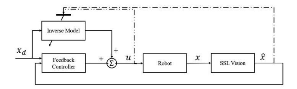
We have been able to improve the prediction accuracy of the robots using both types of models and will be conducting more experiments to choose the best function approximator for the robots' motion models considering the complete control loop. Fig. 3 shows the block diagram of system identification, where $x$ denotes the robot state consisting of the robot pose and velocity, $\hat{x}$ represents the observed robot state, $u$ shows the velocity commands for each wheel, and $x^d$ denotes the desired robot state. It should be noted that the inverse model block on the figure would be replaced by a model predictive control (MPC) block, when the motion model is not invertible such as the case with the kinematic model being a neural network.
We use this learned model to inform our state estimation. In 2017, we used an Extended Kalman Filter (EKF) as our estimation strategy however, this placed restrictions on the motion models. Specifically, the model needs to be invertible in order for it to be compatible with the EKF. We have since converted to an Unscented Kalman Filter (UKF) which is compatible with the new motion models we are testing.
5 Semi-Automated Repair of Robot State Machines
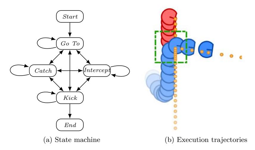
For RoboCup 2018 we are testing an approach to one of the difficulties of writing complex controllers as robot state machines (RSMs). RSMs require reasoning about the transition between states, and even when this logic is correct, it is often parameter configuration dependent. As an example we use a version of our attacker RSM. The attacker has five states, a start state which handles the initial startup of the RSM, a GoToBall state which handles traveling to a slow or motionless ball, Interception, which handles the case of intercepting a moving ball at the correct angle to kick on goal, Catch, which handles the case of intercepting a ball moving directly towards the robot, Kick, which kicks the ball towards the selected target when the robot is correctly setup, and finally Finish, which is entered after a completed kick. There are 12 parameters which are used for determining when to transition between these states. Fig. 4 shows a diagram of an attacker state machine and an example failure and success, where the difference between success and failure is the parameter configuration for the transition into the kick state. In this example the robot travels in the intercept state while attempting to reach the necessary conditions for kick. There are six parameters used as thresholds to determine if a robot is correctly positioned for a kick, and in our failure case these thresholds are never met, causing the robot to follow the ball indefinitely.
Configurations that work on one robot, or in one environment, may not work on another robot or in another environment. While manually tuning the parameters can be arduous and error prone, the debugging process offers the following key insights: the roboticist debugging can frequently identify when something went wrong, which state the behavior was executing, and which corrected state the behavior should have executed for successful operation. With this information we have partial specification of the desired behavior, this specification details what should have happened, but not the complete sequence of states necessary to get there, or the parameter values necessary to achieve it. Based on this, we repair robot state machine transitions as follows:
- Log execution of the robot state machines at run time.
- Replay the logs and provide corrections or reinforcements to a small subset of the state transitions.
- Automatically adjust the parameter of the robot state machine so as to satisfy as many of the corrections as possible.
For the last step of this process we use a novel approach leveraging program repair techniques to reduce the problem of finding parameters which satisfy our human corrections to a MAX-SMT problem over the set off all assertions. Since the tactics in the MinuteBots codebase are written predominantly as state machines, we can then use this system to simplify parameter configuration and the transfer to new robots and environments. Note that updating these parameters is not done in real time, instead happening after games and practices when we have identified failure cases.
6 Conclusion
In 2017, UMass MinuteBots team won the lower bracket finals after placing 4th in our group during the group stage. We improved our software and refined our strategy throughout the week of the competition and managed to defeat RoboTeam Twente 3 to 0 in the lower bracket final, resulting in a final rank of 13th overall. The results for all games played are shown in Table 1.
Our primary goals for this year are threefold. First, we would like to continue to perfect the basics of robot soccer, including control, safe navigation, basic coordination, and development of fully functional and reliable hardware. Second, we would like to extend the capabilities of our previous MinuteBots team by developing more robust advanced tactics such as ball interception, highly coordinated passing, and threat-based defense. Third, we are committed to deploying as much state-of-the-art research on our robots during competition as possible, especially in the areas mentioned in Sections 3-6.
Our long-term goals for RoboCup SSL are centered on continued exploration of the foundational problems and challenges related to both multi-agent systems and long-term autonomy. We believe RoboCup SSL is an excellent platform for exploring both of these topics.
Table 1: Results of the 2017 Matches
| Game | Opposing Team | Goals Scored | Goals Received | Result |
|---|---|---|---|---|
| Group D, Game 1 | ER-Force | 0 | 7 | Loss |
| Group D, Game 4 | RoboFEI | 0 | 0 | Draw |
| Group D, Game 6 | SRC | 0 | 4 | Loss |
| Group D, Game 8 | Kiks | 1 | 1 | Draw |
| Lower Quarter Final | RoboIME | 4 | 1 | Win |
| Lower Semi Final | RoboJackets | 1 | 0 | Win |
| Lower Final | Robo Team Twente | 3 | 0 | Win |
References
- K. Vedder, E. Schneeweiss, S. Rabiee, S. Nashed, S. Lane, J. Holtz, J. Biswas, and D. Balaban, "Umass minutebots 2017 team description paper," 2017.
- J. R. Bruce and M. M. Veloso, "Safe multirobot navigation within dynamics constraints," Proceedings of the IEEE, vol. 94, no. 7, pp. 1398–1411, 2006.
- T. Kalmar-Nagy, R. D'Andrea, and P. Ganguly, "Near-optimal dynamic trajectory generation and control of an omnidirectional vehicle," Robotics and Autonomous Systems, vol. 46, no. 1, pp. 47–64, 2004.