ITAndroids Small Size Soccer Team Description 2019
Benny Mirahy, Éric Machado, Eric Moreira, Francisco Azevedo, Joel da Silva, José Luciano, Maihara Santos, Marcos Máximo, Reynaldo Lima, Riedel Linhares, Rudá Bittencourt, Victor Duarte
Aeronautics Institute of Technology, São José dos Campos, São Paulo, Brazil
[email protected] · http://www.itandroids.com.br/
Abstract ITAndroids is a robotics competition group associated to the Autonomous Computational Systems Lab (LAB-SCA) at Aeronautics Institute of Technology (ITA). ITAndroids is a strong team in Latin America, winning 21 trophies in robotics competitions in the last 7 years. Our Small Size League (SSL) team started its activities in early 2017, after ITAEx, an alumni association, provided financial aid and support to acquire the necessary material to build a Small Size League team. Two years later, this paper describes our efforts on the road to our first RoboCup participation.
1 Introduction
ITAndroids is a robotics research group associated to the Autonomous Computational Systems Laboratory (LAB-SCA) at Aeronautics Institute of Technology. As required by a complete endeavor in robotics, the group is multidisciplinary and contains about 45 students from different undergraduate and graduate engineering courses.
ITAndroids is regarded as one of the best robotics teams in Latin America, winning 21 trophies in robotics competitions in the last 7 years. In Latin American Robotics Competition (LARC) 2018, Latin America's version of RoboCup, our team won 6 trophies, therefore being the team with the most number of trophies in this competition. Moreover, ITAndroids have participated in several (2012, 2013, 2015, 2016, 2017 and 2018) RoboCup competitions in other leagues. In RoboCup 2018, we placed 9th in Soccer 2D and finished top 8 in Humanoid KidSize. Notice that we have also participated in the Small Size league in LARC 2018.
We intend to participate for the first time of the Small Size League (SSL) in RoboCup Sydney. As a new team, we want to participate in Division B in order to gain experience. After two years of development, we are finally able to participate with other teams in this world tournament.
This paper presents our efforts in developing a Small Size team to compete in the Robotics World Cup. The rest of the paper is organized as follows. Sec. 2 introduces electronics projects. Sec. 3 explains mechanical designs and development works. Sec 4. presents our software development. Sec 5. concludes and acknowledgments.
2 Electronic Design
The electronics project was based on the RoboFEI open source project [11]. The team uses a modified version of the main and kicker boards from the open source project. Over the last two years the electronics team has worked on understanding and using correctly the most important features, as well as implementing its own low-level logic to improve the robots' functionality.
2.1 The Main Board
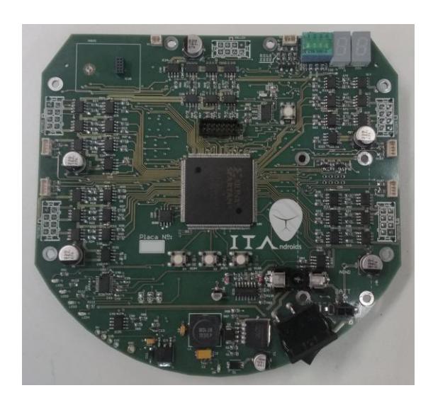
The main board is responsible for processing all logic functions with a Xilinx Spartan 3 FPGA board as the component responsible for realizing the embedded computations and the robots' motion control as shown in Figure 1.
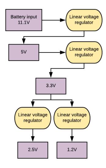
Power Supply A 3 cell 2200 mAh LiPo battery is used to power the main board. The input ranging from 11.1 V to 12.6 V is received by circuitry consisted of various linear voltage regulators capable of giving the board inputs of 5 V, 3.3 V, 2.5 V, and 1.2 V. This is responsible for powering every component of the board, except the motors and their drivers, which bypass the regulation circuit and receives its energy directly from the battery. Figure 2 illustrates how the battery voltage is transformed into suitable values for each part of the board.
Data Processing For simplicity reasons, the FPGA was used partially with the Microblaze soft core microprocessor provided by Xilinx. For the implementation of the features of the board like the brushless motor MOSFET drivers, the AD converter, the radio and DIP switches, ITAndroids used the Intellectual Property Cores (IP Cores) released by RoboFEI. These IP Cores serve as libraries programmed in VHDL that contain the functions used to integrate components from the main board with the firmware and, thus, with the software instructions received from the communications module.
Communications The Radio used to communicate with the external computer is the commonly used NRF24L01. The data received from the high-level software includes reference wheel speeds, and kicking instructions. This information is processed in the robot's firmware, which converts the commands into electrical signals sent to the individual components. The current state of the project uses an Arduino Uno with an NRF radio as the communication station that links the computer and each of the robots. In order to achieve a more robust design, the electronics team plans on developing a specific board for the radio station in next year's iteration.
2.2 The Kick Board
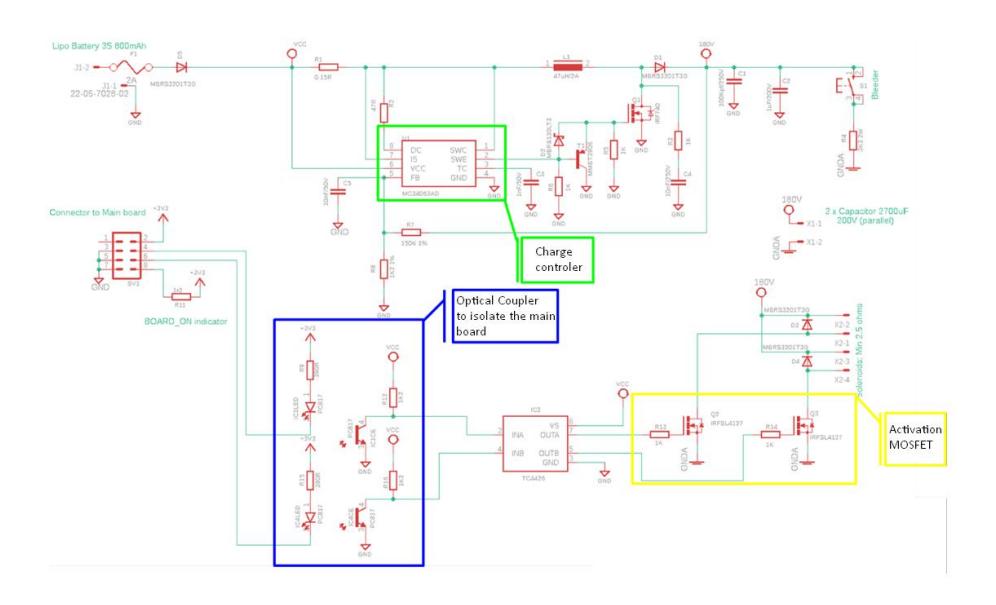
The electronic kick system is contained in a separate circuit board opto-coupled to the main board, for safety measures since it is a power circuit. The purpose of the kick board is to control the charging of two capacitors of 2200 µF, which are connected in parallel, to a voltage of 180 V through a DC-DC converter.
If the main board sends a signal to execute a kick, a MOSFET will be activated and all the energy stored in the capacitors will be discharged onto a solenoid that, with the magnetic field generated by the passage of the current in its winding, will move a plunger to effectively kick.
2.3 Electronics Work in Progress
In 2019, the team is reformulating the electronic project, especially the boards' layout. Most of the modifications include changing the types of electric connectors used and their positions in order to have a better integration with the mechanic design. We are also removing unused components like buttons and a 7-segment display. Moreover, for the next iteration of the ITAndroids Small Size robots, new 50 W Maxon motors will be used. To support these new, more potent motors, the boards' power supply is being repurposed. As for the kick board, a new board will be made with optimized routing so that better connectors may be used. This board will be equipped with a functional button that discharges the capacitors, for safety reasons. Finally, as mentioned in section 2.1, a new custom communications station will be made, equipped with the NRF24L01 radio and an antenna for increased communication range, over the current setup with the Arduino Uno.
3 Mechanical Design
Our robot was designed based on Skuba's [13] open source mechanical project and we acquired some knowledge and information with FEI and IME researchers, who helped a lot by sharing their experience. Adapting the Skuba's project to the team's manufacturing methods, machinery and materials, we designed a new robot, focusing in a project that is easy to manufacture and test.
3.1 Designing
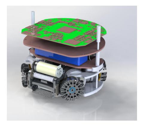
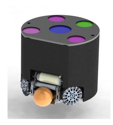
Overview The 3D model CAD was made based in Skuba's [13] available part drawings. The team used Dassault Systèmes SolidWorks for drawing and assembling the parts. The project was modified to adapt to the team's manufacturing methods. In addition, the Skuba's project featured different mechanical actuators, thus it was necessary to create some parts and suppress others. Figure 4 shows the core mechanical parts in an assembly drawing and Figure 5 shows the complete robot's CAD.
The robot is composed of four omnidiretional wheels, allowing it to move in any direction. Each one of these wheels is powered by a Maxon EC45 flat brushless motor [6]. Each wheel also contains an internal gear that connects it to the motor's axis. An encoder is attached to the back in a extended shaft for measuring wheel velocity.
The robot also consists of two kicking systems: the plunger and the chip kicker. The plunger allows horizontal kicking and the chip kicker allows vertical kicking. The robot also has a dribbling system, which is able to hold the ball while the robot is driving it.
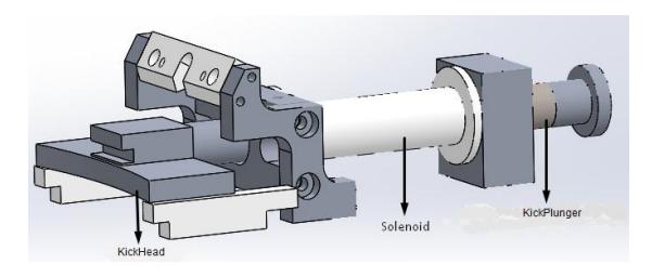
Kicking system the team had a few options to choose from: a spring based mechanism, a pneumatic based mechanism, and a solenoid based mechanism. Out of the three possibilities, the main factors to analyze are shooting power, space occupied, time between each shot, safety, and number of total shots in a game. With that in mind, ITAndroids opted to implement a solenoid based kicked mechanism, mostly because of the guarantee that it would work for the team's first Small Size robot, since it is the choice most SSL teams use.
The robot's shooting system is composed by an inductive resistance in which, when a high current passes travels through the wrapped coil, a magnetic field is created. This field interacts with a ferritic stainless steel shaft, thus converting the energy stored in the two 2200 µF 200V capacitors into a mechanical impulse. Figure 6 illustrates the parts of the kicking subsystem.
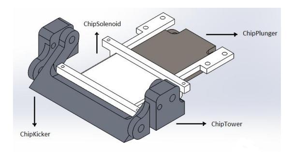
Chipping system consists of a rectangular solenoid mounted under the cylindrical solenoid of the kicking device. Its working mechanism is quite similar to that of the kicking system. So far, ITAndroids has designed its chipping system, but the team has not manufactured it yet. As we still do not have a mature enough software, due to the project still being in early development, we decided to not devise our limited effort into making the chipping system work, but we designed the mechanics so this system may be easily integrated into the robot in the future. Figure 7 represents the parts of the chipping system in assembly.
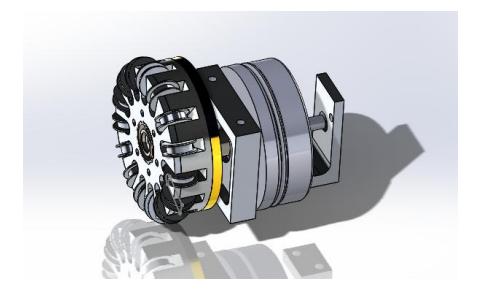
Motion system composed by motor mounts, encoder mounts, motors, and wheels. There are two possible and symmetrical configurations for the mount assembly.
The motor mount: the motor mount is a structure responsible for holding the motor and the wheel axle. The wheel axle (8mm) is held by pressure, using a M3 screw to fix it. Three M3 screws hold the motors next to the motor mounts.
The encoder mount: the encoder mount holds the encoder. There are four encoder mounts in the structure and they are all equal.
The motor: the motor used for motion is a Maxon EC45fl-200142 [6] brushless DC motor.
The wheels: these are the most complex part of the motion system. The omnidirectional nature of these wheels add the need for freedom of movement in the direction parallel to the rotation axle.
- The gear: the gear used is a 72 teeth internal gear. The pinion gear is a 20 teeth gear, thus we have a 5:18 gear ratio.
- The wheel hub: this is the central part of the gear, in it the gear is fixed with five M2 counterbored screws. The wheel rollers are placed in this part of the wheel.
The wheel rollers: the wheel rollers are 15 small rollers placed around the hub (with 3mm wire). O-rings are placed around the rollers to increase friction with the floor.
The wheel cover: the cover closes the wheel assembly and holds the rollers.
Figure 8 shows the motion system.
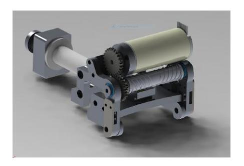
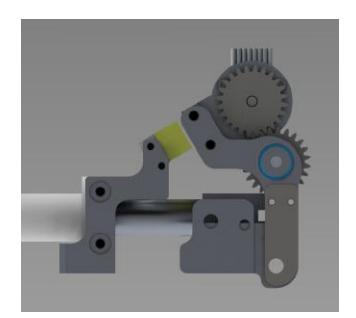
Dribbling System this is a ball control system using a Maxon 283856 motor with 1:1.04 transmission and a roller bar with splines designed for centering the ball. The system is mounted on a pivoting axis structure to absorb ball impacts and a pair of fixed rubber bumpers is used on the back.
By analyzing the materials used by other teams such as RoboFEI, Tigers, and OP-AMP, a silicone rubber material with 25 Shore A hardness was selected for the dribbler roller. The configuration of multiple splines mirrored from the end to the center of the shaft to centralization of the ball and final nominal rotation of 10,226 RPM proved effective in dominating and centralizing the ball in simulations and practical tests. Losing dominance only in the robots rotation movement which can be tested with different dribbler rotations or limiting the speed of rotation of the robot. Figure 9 shows the dribbling system.
4 Software
The code has been planned and divided in several modularized parts, so that each part can be separated from the others with ease. Our team uses two opensource softwares: grSim [8], used for testing the software, and SSL-Vision [15], the shared vision system for the Small Size League.
4.1 Embebded Software
As described in Sec. 2, our electronic design is based on the RoboFEI project [11], which uses an Xilinx FPGA with an embedded Microblaze microcontroller.
After an initial phase of getting acquainted with RoboFEI's embedded code, we decided to maintain the VHDL (VHSIC Hardware Description Language) code while completely rewriting the C code which runs on the Microblaze. Our embedded code follows an object-oriented style, especially adapted to the C language. The embedded code encompasses the following main classes:
- Communication: encodes and decodes messages based on the team's protocol.
- RF24: deals with the nRF24L01 radio. This class was adapted from the RF24 Arduino library [14].
- LowPassFilter: first-order low pass filter used for filtering noisy measurements.
- Motor: drives a brushless motor.
- Encoder: represents an encoder, which may be an actual wheel encoder or a Hall sensor based encoder.
- PIController: represents an abstract PI digital controller, which is used for controlling the motors. Gains for the digital controller are computed using Tustin transform.
Regarding motion control, the robot receives desired speeds in forward, sideways, and rotational directions and transforms them into wheels speeds. For each wheel, we adopt a SISO control loop endowed with a PI compensator, therefore coupling between wheels is neglected during controller design. Since the US Digital encoders were not mounted in the robots in 2018, we used the Hall sensors as encoders. Despite the noisy measurements, we were able to adequately control the wheel motors using a sample time of 5 ms. Since the dribbler motor has only one pole pair, we decided for a longer sample time of 20 ms in this case.
The control loops' update rates were selected by trial and error using a Simulink simulation which included encoder quantization. We also considered the phase margin lost due to discretization delay in this decision. We expect to have a higher update rate for the wheel motor when the US Digital encoders are mounted, which will allow higher control bandwidth.
For designing the PI gains, we considered bandwidth and phase margin requirements for each control loop. The motors' parameters were obtained from the manufacturer's datasheets [6, 7] and the wheel's inertia was estimated from CAD files. The robot's inertia effect on the wheel's plant has already been modeled, but we have not taken it into account in the control loop design yet. No current control loop was implemented.
When designing the controllers' gains, we consider the delay of T$^s$/2 introduced by discretization, where T$^s$ is the sample time. To take this into account, we use the Pade approximation. Since this result in high order transfer functions, we use a numerical optimization procedure through the fminsearch MATLAB function to compute the gains. In order to provide an adequate initial guess to fminsearch, we first compute the gains analytically by neglecting the delays.
4.2 Localization
Stochastic filtering techniques are used for improving the estimates used in highlevel control and decision making. For ball tracking, we use a linear Kalman Filter, whereas for teammates localization, we use an Extended Kalman Filter (EKF) to take into account the nonlinear dynamics of the robot. The covariance matrices used in filter design were selected by trial and error. However, we expect to run experiments to identify the actual covariance matrices. Moreover, we intend to implement system delay compensation as described in [12].
4.3 Action Planning
The decision making used is based on role assignment and isolated logic for each role, focusing on an agent based AI instead of hardcoded plays and tactics.
There are currently four roles considered within the strategy layer: Goalie, Defender, Main Attacker and Support Attacker. All the roles except the Main Attacker are defined by a certain Behavior Tree [4], meaning that each agent belonging to each one of these groups at any given moment has an isolated tree representing the robot's behavior.
The main advantages of this strategy structure are the scalability and the behavior modularization. As a first iteration, the Behavior Trees used for each role are simple and do not contain more than 3 layers, but in case the strategy becomes more complex the Behavior Tree will scale well.
The Goalie uses a simple default semi-circle behavior as described in [5]. The Defender uses a Threat-Based Positioning approach as described in [2], but has a default position defined by a Delaunay Triangulation positions set in case of no threats. The Support Attacker only has Delaunay positions but uses it only in case it has not received any request for positioning from the Main Attacker.
The Main Attacker uses an Action Chain algorithm in order to maintain an agent based AI approach but easily make cooperative offensive plays. The Action Chain algorithm is described in detail in [1]. If the Main Attacker decides to make a cooperative play (like a pass, for example) it overlay the Support Attacker behavior logic.
4.4 Trajectory Planning
This section refers to the path finding problem, where an object (in this case, a robot) must navigate from one point of the map to another avoiding obstacles. This problem is specifically complex in the Small Size League domain because of the fast moving robots and high dynamic games.
The path planning algorithm used is an ERRT (Extended Rapidly-Exploring Random Tree) [3]. The ERRT version we implemented has some modifications and heuristics which differ from the original algorithm, as described in [10].
4.5 Software Work in Progress
This year we plan to optimize our behaviors before developing more complex action planning. The defense behavior will be optimized using a Supervised Learning system with Hungarian Algorithm to assign defenders to opponent attackers. We also expect to have a new marking behavior using Deep Reinforcement Learning, similar to the one described in [9].
The high-level control will be optimized for dribbling and navigation, as will the trajectory planning algorithm. We expect that the focus of our development until RoboCup will be on optimizing basic behaviors, and localization and control algorithms.
We are also developing a new Graphical 2D Interface connected to grSim [8] in order to help in development and debugging.
5 Conclusions and Acknowledgements
This paper describes some of our efforts during the years of 2017 and 2018, providing some insight on how we used several open source projects to quickly build a working team. We currently have 2 working robots, but we expect to participate in RoboCup with 5 units (unfortunately, we will not be able to build a 6th robot this year due to budget limitations).
Regarding immediate future work, we are currently redesigning our robot in order to have a better integration between electronics and mechanics and to improve the system robustness. Moreover, the design is being adapted to the new 50 W motors. Until RoboCup, we also expect to improve our basic high-level behaviors as well as our localization and control algorithms.
We would like to acknowledge the RoboCup community for sharing their developments and ideas. We specially acknowledge RoboFEI and Skuba for open sourcing their electronic and mechanic designs, respectively, since our current design is heavily based on their designs. Moreover, we would also like to thank members from CMDragons, RoboFEI, and RoboIME for helping with many questions. Finally, we thank our sponsors Altium, Intel Software, ITAEx, Metinjo, Micropress, Polimold, Rapid, Solidworks, ST Microeletronics and Virtual Pyxis. We also acknowledge Mathworks (MATLAB), Atlassian (Bitbucket), and JetBrains (CLion) for providing free access to high quality software.
References
- H. Akiyama, S. Aramaki, and T. Nakashima. "Online Cooperative Behavior Planning Using a Tree Search Method in the RoboCup Soccer Simulation". In: 2012 Fourth International Conference on Intelligent Networking and Collaborative Systems. 2012, pp. 170–177. doi: 10.1109/iNCoS.2012.83.
- Joydeep Biswas et al. "Opponent-driven Planning and Execution for Pass, Attack, and Defense in a Multi-robot Soccer Team". In: Proceedings of the 2014 International Conference on Autonomous Agents and Multi-agent Systems. AAMAS '14. Paris, France: International Foundation for Autonomous Agents and Multiagent Systems, 2014, pp. 493–500. isbn: 978-1-4503-2738-1.
- J. Bruce and M. Veloso. "Real-time randomized path planning for robot navigation". In: IEEE/RSJ International Conference on Intelligent Robots and Systems. Vol. 3. 2002, 2383–2388 vol.3.
- Michele Colledanchise and Petter Ögren. "Behavior Trees in Robotics and AI: An Introduction". In: CoRR abs/1709.00084 (2017). arXiv: 1709.00084. url: http://arxiv.org/abs/1709.00084.
- M. Mauelshagen et al. "Tigers Mannheim Team Description for RoboCup 2012". In: (2013).
- Maxon. Maxon EC-45 Flat Motor Datasheet. https://www.maxonmotor.com/medias/sys_master/root/8830904893470/2018EN-265.pdf.
- Maxon. Maxon EC-max 22 Motor Datasheet. https://www.maxonmotor.com/medias/sys_master/root/8830475272222/2018EN-223.pdf.
- Valiallah Monajjemi, Ali Koochakzadeh, and Saeed Shiry Ghidary. "grSim – RoboCup Small Size Robot Soccer Simulator". In: RoboCup 2011: Robot Soccer World Cup XV. Ed. by Thomas Röfer et al. Berlin, Heidelberg: Springer Berlin Heidelberg, 2012, pp. 450–460. isbn: 978-3-642-32060-6.
- Alexandre Ferreira Velho Muzio. "Curriculum-based Deep Reinforcement Learning Applied to Humanoid Robots". Master's Thesis. Aeronautics Institute of Technology, 2018.
- Igor Franzoni Okuyama. "Trajectory Planning Considering Acceleration Limits for an Autonomous Soccer Player". Bachelor's Thesis. Aeronautics Institute of Technology, 2017.
- Danilo Pucci et al. "Robofei 2014 team description paper". In: (2014).
- Michael Sherback, Oliver Purwin, and Raffaello D'Andrea. "Real-Time Motion Planning and Control in the 2005 Cornell RoboCup System". In: Robot Motion and Control. Ed. by Krzysztof Kozłowski. London: Springer London, 2006, pp. 245–263. isbn: 978-1-84628-405-2.
- J. Srisabye et al. Skuba 2009 Team Description of the World RoboCup 2008. Kasetsart University, Thailand, 2009.
- TMRh20. Building Robots for RoboCup Small-Size Category MauaBots Team. Centro Universitário FEI, Brazil.
- S. Zickler et al. "SSL-vision: The shared vision system for the RoboCup Small Size League". In: (2009), 425 to 436.