Immortals 2019 Extended Team Description Paper
Omid Najafi Koopai, MohammadAli Ghasemieh, Mehran Khanloghi, AliReza Mohammadi, AmirMahdi Matin, AmirMahdi Torabian
Sharif University of Technology; Pars University of Art; University of Tehran; University of Science and Technology
http://www.immortals-robotics.com
Abstract This paper describes the recent works done by the Immortals team, a team consisting of undergraduate engineering students, currently focusing on the Small Size League. There were changes applied to the mechanics and electronics of the robots in the previuos year. This year, the team focused on solving the issues which were observed during the recent competitions including RoboCup 2018, Montréal. The goal is to achieve a reliable design where there is no need for any robot substitution due to damages during a match. In addition to the current robot, there is a 3D printed robot which was introduced in the previous year by this team and has been improved and tested in the recent competitions.
Introduction
The Immortals Robotics Team is a team of undergraduate students from Sharif, Tehran and Pars University. The team started the Small Size League (SSL) project in the summer of 2007 and produced its first robot after one year, there have been major revisions made in the designs of the robots since then. In this paper the most recent changes on the designs and achivments made by the team will be shared with the reader whom, wants to design or modify an SSL robot. There is also a new type of robot which was introduced by this team in the past year known as the 3D-Printed robot [1,4].
Mechanics
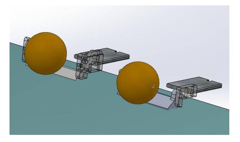
In the past two years there were multiple changes applied to the chip kicker in order to reach the most efficient design. A great number of simulation tests were done on every chip design and after a successful test, the parts were manufactured for real world testing procedures.
2.1 Chip kickers new design
Chip kicker is a part which should have a high resistance against impacts, it has to be efficient in transmitting the force applied to it from the chip kickers plunger to the ball. The first improvement in the chip kicker is that $\theta$ (angle between a line which passes through the chip kickers axis of rotation and impact point and the direction of the force vector)has been increased to 90 degrees. With this improvement the force applied to the chip kicker will be completely in the direction of the angular acceleration of the chip kicker. According to the torque relation, It is shown that when the angle between the force and the distance vector turn into 90 degrees, the ball would receive the most impact from that force.
The other improvement is to increase the moment of inertia around the chip kickers axis of rotation. This way, more angular acceleration can be achieved by the chip kicker.
In this section a function for angular acceleration of the chip kicker will be driven. As known, the relation between the moment of inertia around the chip kickers axis of rotation and sum of torque applied to the chip kicker can be written as:
$$\sum T = I\alpha \tag{1}$$
$$T = Fb \tag{2}$$
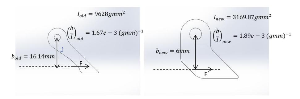
Equation 1 is one of the general equations of motion for rigid body in plane motion [7]. Although the chip kicker is a 3D model in real life but the most important part of the chip kicker (which is shown in Fig.2) is the design of the arms of the chip kicker which can be discussed in 2D (The arms of the chip kicker which is shown in Fig.2 are the same at both left and right sides of the chip kicker assembly. For 2D analysis we neglect the thickness of this part).
b is the vertical distance between center of pin of the chip kicker and point which force is applied.
T is torques applied to the chip kicker. In this problem there is only one torque which is applied to the chip kicker and in equation 2 this torque is defined.
$\alpha$ is the angular acceleration of the chip kicker.
I is moment of inertia around the axis of rotation of the chip kicker.
F is the force applied to the chip kicker by the plunger.
It is not necessary to calculate the impact force accurately thus, it is assumed that the force applied, is constant to reduce the parameters involved in the new chip kickers design, the impact force is approximated by the equation below:
$$F = \frac{m_{plunger}V_{f-plunger}^2}{2d} \tag{3}$$
Where $m_{plunger}$ is the mass of the plunger and $V_{f-plunger}$ is the velocity of plunger exactly before the impact and d is the distance in which the plunger and the chip kicker are in contact during the impact.
Below is an expression for the angular acceleration, resulted from the previous equations:
$$\alpha = \frac{bm_{plunger}V_{f-plunger}^2}{2Id} \tag{4}$$
By assuming F as constant¹, The angular acceleration will be a function of:
$$\alpha = f(\frac{b}{I}) \tag{5}$$
¹ Constant force assumption is because of the very low period of time which the plunger and chip kicker is in contact. It is assume that the force won't change significantly during the impact.
As a result, if the moment of inertia around the axis of rotation reduces by decreasing the mass of the chip kicker or reducing the distance between its center of mass and the axis of rotation, $\alpha$ will increase. As shown in Fig.2, $\frac{b}{I}$ is calculated for both old and new designs:
Electronics
Last year there were major changes applied to the design of the electronics. At the time of writing this paper, it has been about one year which these circuits were used and have been tested and qualified in different matches. Currently all the robots (including the 3D-printed robots) are functioning with the help of these circuits. The reader is referred to the previous years TDP [1]of this team for more details about the main circuit.
For this year, (1)There have been some research made for designing the teams future sender base in order to communicate with a great number of robots. (2)A new type of motor encoder is used for a better and more reliable robot navigation.
3.1 Communication
Last year, teams in division A were permitted to use 8 robots in the field during the play, in the next years this limit will increase to 11. This fact comes with different challenges for all teams related to there robots communication system.
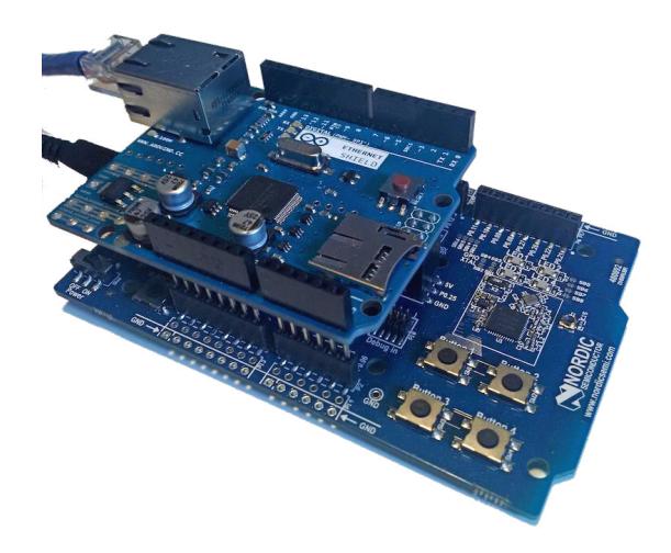
Number of links to every robot from a senders base, bit rate and packet size limit are the three parameters that have an inverse relationship with each other. Some teams solve this problem by using two or more sender bases, each controlling a set of robots. A few other teams decided to send there data with a lower rate or smaller packet size. In the Immortals team the goal was to use a single sender base without reducing any of the three parameters. Using the same type of RF module on the main circuit of the robot [2]. Currently the sender which is used to communicate with the robots, is using a RF module called the nRF24L01 from Nordic Co., The RF module implemented on the robot is nRF52832 which also is from Nordic Co.. Both the modules are capable of using the Enhanced ShockBurst protocol (ESB) and are currently using that protocol to communicate. The nRF24L01 acts as a bottle neck for the system since it has a slower bit rate in compare to the nRF52832 Thus, it is decided to design a sender base with the nRF52832.
By using an nRF52 Development Board and an Arduino Ethernet Shield it is possible to setup a simple sender base equipped with the nRF52832 module (see Fig. 5).
After running many tests the average amount of packet loss for the link between the sender and the robot was negligible (less than one packet loss among 60 packets per second on average). Using the previous sender of the team (nRF24L01)the average packet loss was one or two out of 60 packets. Although this might not be a concern when the robots can still get navigated properly with a few packets lost, it may be important for teams that wish to run 11 robots in the future.
3.2 Magnetic Encoder
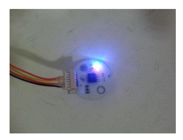
Until last year the robots were equipped with a disk encoder which required the motor to have a back shaft, If the backshaft bends slightly due to very hard collisions made with the wheel, the disk encoder will malfunction and in extreme cases the encoders disk and ciruit will hit each other resulting in the damage of the encoder itself.
It was decided to use magnetic encoders due to the explained issues. The type of encoder which the team currently uses is TLE5012B-E1000 [5], The previous disk encoders were the E4T-500 Miniature Optical Kit Encoderers [6].
After using the magnetic encoder the precision of the motor speed increased by a factor of 8 due to the high resolution of the magnetic encoders, there were no robot substitutions due to malfunctioning encoders, the process of assembling and disassembling a robot got very fast and easy, the motors we used were not needed to be specially customized which takes much time to get prepared by the manufacturer.
On the other hand the magnetic encoder outputs are a little vulnerable to noise and the data gets invalid when a strong magnetic field gets presented, For example when the robot performs a kick the encoders will give an invalid data output for a few tens of milliseconds.
Software
At the time of writing, the main software has not improved much. There are some functionalities which got added to navigate the robots in a more controlled and smooth way, some structures were changed in the software to be able to implement state machine code which made it able to perform tasks like ball placements.
References
- Najafi, O.,Ghasemieh, M.A.,Khanloghi M. :Immortals 2018 Team Description Paper. RoboCup 2018 SSL, (2018).
- Nordic Co. https://infocenter.nordicsemi.com/pdf/nrf52832_ps_v1.0.pdf.
- Nordic Co. 2.4 ghz rf system-on-chip, transceivers and audio streamer www.nordicsemi.com.
- Immortals Open Source Project. https://github.com/maghasemieh/immortals_ssl_opensource_mech.
- Infineon Co. https://www.infineon.com/cms/en/product/sensor/magneticposition-sensor/angle-sensor/tle5012b-e1000/.
- US digital Co. www.usdigital.com/products/e4t.
- J.L. Meriam, L. (n.d.). Engineering mechanics dynamics.