KIKS Extended Team Description for RoboCup 2019
Shin Ohno, Yusei Naito, Toshiki Mimura, Koh Ohno, Yasutaka Tsuruta, Ryoma Mitsuoka, Ryo Sako, Masato Watanabe, Toko Sugiura
National Institute of Technology, Toyota College, 2-1 Eisei-cho, Toyota, Aichi 471-8525, Japan
www.ee.toyota-ct.ac.jp/~sugi/RoboCup.html
Abstract This paper is used to qualify as participation to the RoboCup 2019 small size league. Our team's robots and systems are designed under the RoboCup 2019 rules. The major points of improvement in this year are about acceleration performance of robot and redesign in AI system. The overviews of them are described. In addition, it is reported about the evaluation of USB3.0 camera for SSL-Vision.
1 Introduction
Continuing from last year, KIKS has been aiming to develop higher-performance hardware and smart AI system. Toward the realization of precise pass-play, we improved about the acceleration performance and driving stability of the robot for hardware, and action decision algorithm and dynamic assignment of robots to agents for software. In addition, we tried to test the USB3.0 camera for the use of SSL-vision.
2 Hardware improvement of the robot
As increasing the playing field area of RoboCup Small Size League, the running performance of the robot should be very important. Our robots have been developed based on the use of 70 w brushless DC motor, with the aim of improving that performance since 2016. The biggest feature of this change is the expectation of the maximum speed improvement. In 2016, we realized the mounting of 70 w brushless DC motors without changing most of existing functions. After 2017, we have refined chassis and other whole parts' design for motor mounting, configuration of main circuit board, introduction of new boost circuit. While the theoretical maximum speed rose up, however, there was less chance of reaching the maximum speed during the game. Therefore, we were not able to demonstrate the expected acceleration performance. In addition, the control performance at high speed movement was not sufficient, because of the contact instability between the robot and the carpet surface. In this section, we focus on improving the acceleration performance and the stability at high-speed movement of the robot, and propose an improvement method.
2.1 Improvement of acceleration performance
The slip of the omni-directional wheel is one of the reason of poor acceleration performance on our robot. In order to solve this problem, it is effective to increase the frictional force between the wheels and playing field surface, as well as the slip suppression control method mentioned in our previous TDP [1],[2]. In order to increase the frictional force of the wheels, the enhancement of the wheels' grip force with ground surface and increasing the weight of the robot itself are effective methods. Thus, in this subsection, we describe the results trying to improve acceleration performance focusing on enhancing strength of small tires and weight of robot.
Rubber materials such as o-ring are conventionally used for small tires to increase the grip force as omni-directional wheels, such as described in ref. [3]. In general, however, the o-ring break and drop off by severe use during the game. The dropped o-ring not only causes deterioration of the acceleration performance of the robot itself but also disturbs the running of other robots. Thus, in order to increase the strength of the small tire, the ratio of the outer diameter to the inner diameter of the rubber ring covering the small tire was made larger, i.e., 1.57 to 3.75. The present and previous small tires are shown in Fig.1.
The reason for increasing the ratio is to enhance the strength against the load during running by increasing the cross sectional area. As a result of this change, the rubber of the small tires on the driving wheel almost never ruptures and never drops off during the game after 2017. This fact shows the effectiveness of this improvement.
On the other hand, the increase of weight of the robot was examined to increase of the normal force to the floor by the driving wheels. The base plate was changed to brass, which has a specific gravity of 3 times as compared with the conventionally used aluminum alloy. The base plate is located at the lowest part of the body and fixes the motor unit, the kicker unit, and the dribble unit. This change effectively realizes weight increase and lower-center of gravity of the robot compared with method placed simply a weight in empty space. We investigated the weight of each unit of the robot. The results are tabulated in Table1. That is, by changing the material of the base plate, the weight could be increase by 260g. As the result, the position of the center of gravity could be lower by 3.5mm, and the stability of acceleration and the running performance was expected. With the increase of the weight, however, more energy is required for acceleration, so it is necessary to verify the balance between the motor power and the weight of the robot in detail.
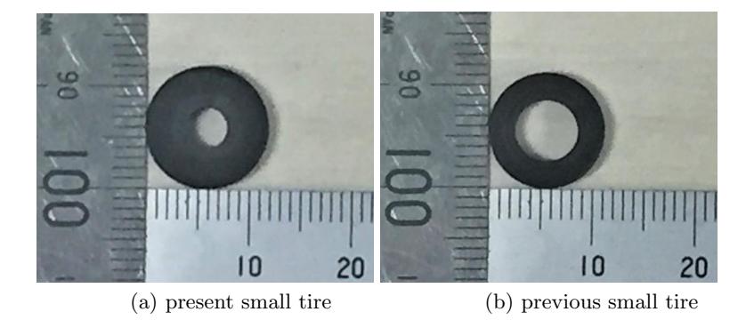
Table 1. Weight of robot's equipment
| Equipment | weight[g] |
|---|---|
| Circuit unit | 440 |
| Dribbler | 240 |
| Motor unit | 990 |
| F rame | 20 |
| Cover | 220 |
| Base plate(A2017)/(Brass) | 130/390 |
| T otal | 2,040/2,300 |
2.2 Improvement of driving stability of the robot
In general, the ring wheel is used to enable omni-directional movement for the robot in SSL. But, its use causes instability for the running performance of robot, because of the structural characteristics attributed to configuration consisting of multiple small tires. That is, rolling resistance of small tires on axle have a large influence on traveling, and as the results, the running performance could be deteriorated. Furthermore, since the shape of omni-directional wheel generally used in SSL is not precise circle but a polygon, it is main reason for vibration of the robot caused when it is running. The vibration will be consequently bigger on high speed running, and it causes instability of the running performance. For another factor causes deterioration of running performance, there is friction resistance with the carpet of the game field.
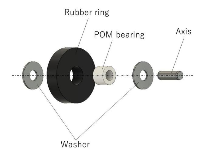
The carpet has different hardness depending on the material and manufacturing method. If it is too soft, the small tires are completely buried in the carpet, and the function of the omni-directional wheel is lost. In that case, therefore, it is necessary to change the control parameters corresponding to the competition field. In this subsection, we describe the reducing method for the rolling resistance in small tires, suppressing method for bouncing at high speed running, and reducing method for frictional resistance with the carpet. We refined the structure of shaft and the bearing to reduce the rolling resistance on the ballless bearing of the small tire. In order to realize a smooth running of a robot, conventionally, the clearance between the metal shaft and the bearing has been required to be large to cope with the incorporation of hair of a carpet and application of a lubricant to a contact portion. The application of the lubricant causes residual dust in the shaft, resulting in large rolling resistance in that part. Some teams have reduced resistance by attaching ball bearings to inside the small tire[4],[5], but if there are 20 small tires on one omni wheel, 80 ball bearings are required for one robot. It increases the moment of inertia and cost. So, we reduced the contact area with the shaft by reducing the inner diameter of the small tire. And by introducing the POM (polyoxymethylene) resin bearing with high self-lubricity, there is no need to apply lubricant. The structure of new small tire unit is shown in Fig.2.
As a result of reducing the allowance between the shaft and the inner diameter of the POM resin bearing, the dust entered very little into the part, and the performance of mobility as well as maintenance were improved. Although there was concern about the strength when changing from metal ball-less bearing to POM resin bearing, it was found that there was no problem in practical use because it was never broken even if it was used for two years. In the previous omni-directional wheel, stainless steel and brass metal were used as bearing and internal gears of small tire, that is, the increasing the weight of wheel itself and moment of inertia was a problem. We realized a reduction for the moment of inertia of the wheel by introducing the direct driving motor system [1] and redesigning small tires, and improved responsiveness and controllability. In addition, it could be manufactured cheaply compared with use of ball bearings and metal shafts.
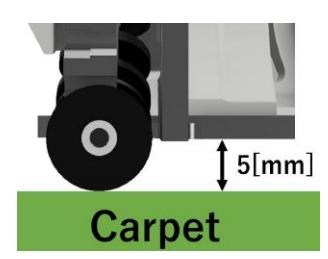
We tried to close the shape of omni wheel to a regular circle in order to suppress bouncing when moving at high speed. That is, by increasing the number of small tires, we attempted to reduce the vibration that cause bouncing[6]. As mentioned above, by reducing the diameter of the small tire shaft and thinning the small tire unit, the number of small tires could be increased from 16 to 20. As the result, the difference between the highest part and the lowest part assuming a simple polygon can be reduced from the conventional 0.88mm to 0.33mm. So, the vibration during the running decreased, and the bouncing at high speed movement was suppressed. We increased the ratio between outer diameter and inner diameter of small tires to reduce the resistance between wheels and carpet during running. By increasing 1mm for outer diameter and setting the small tire to more outside, it prevents the situation that the small tire is buried in the carpet with long hair. As described above, since the allowance between the inner diameter of POM resin bearing and the axis is small, even if the small tire is enlarged, there will be little influence of unevenness. The diameter of the small tire was determined to be 5mm between the base plate and the floor surface when the robot was placed on a rigid floor as shown in Fig.3. With this improvement, the running performance of the robot was less dependent on the condition of the carpet and could be maintained without major change of control parameters.
2.3 Camera evaluation for SSL-Vision
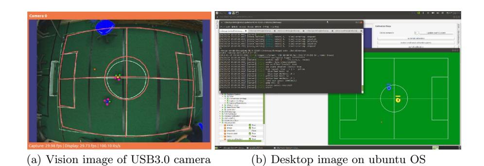
It was evaluated about the use of the USB3.0 camera for the SSL-Vision. We have continuously performed science classes (soccer mini game) at outside school for elementary and junior high school students (including normal adults) using small size robot and a camera of SSL-Vision for more than 7 years. In previous, since it was a system using the recommended IEEE1394B camera (AVT Stingray F046C) as a video camera, a heavy desktop PC was required, which took much time to transport and set up. Thus, in this year we rebuilt the system using one third cheaper USB3.0 (FLIR Blackfly: BFLY-U3-05S2C-CS, Resolution 808*×*608, Frame Rate 50FPS) camera shown in Fig.4 that has nearly equivalent performance and also works on laptop PC as shown in Fig.5. On the wiki, recommended cameras of USB2.0 and GigE for SSL-Vision are described[7], but we tried a USB3.0 camera not listed. When using this USB3.0 camera, it should be downloaded Software Development Kit (SDK: FlyCapture2 Full SDK) from FLIR products site and installed it in the same way as using GigE cameras of FLIR products. After installing the driver, SSL-Vision must always be built or rebuilt.
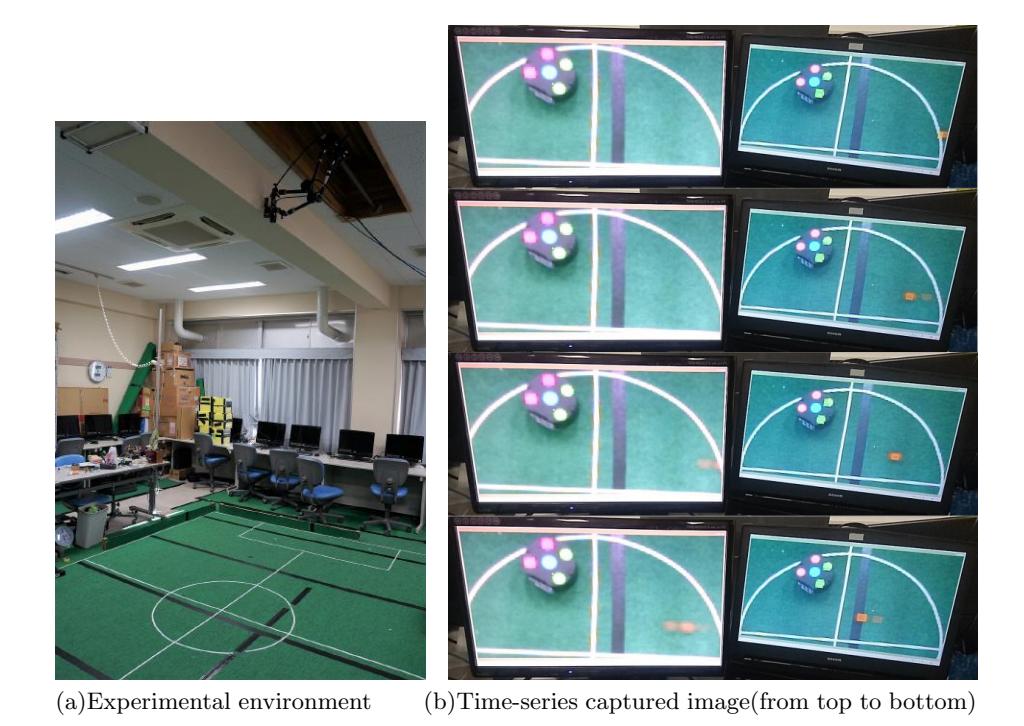
The evaluation of performance of the camera was carried out in the environment where the robots actually operate. It was compared the experimental results of three times for captured images from the AVT STINGRAY and FLIR Blackfly cameras with the detail specifications shown in Table 2. The capture condition of both cameras were almost same. The PCs used for evaluation have the performance tabulated in Table 3. Both cameras were mounted next to each other at a height of 2.6m and rolled the ball from the right side. Both of the display screens have the same speed as the camera frame rate. Figure 6 indicates the experimental environment and the time-series four frame images obtained simultaneously by high-speed capturing from both cameras at 30fps. When the ball enters the semicircle, we can see that the right image captures the ball before that of left. As the result of detailed analysis, it was found that the USB3.0 camera can take information two frames faster, that is, about four frames at vision conversion (60fps) than IEEE1394B camera. Although it can not be said accurately because PC and camera conditions are not same, it is unlikely that it will be delayed by 4 frames due to the difference in computer performance. This result suggests that the USB3.0 camera is more responsive than the firewire standard products. In addition, under our experimental conditions, the difference between 50fps (Blackfly) and 61fps (Stingray) of frame rate did not significantly affect the motion of the robots.
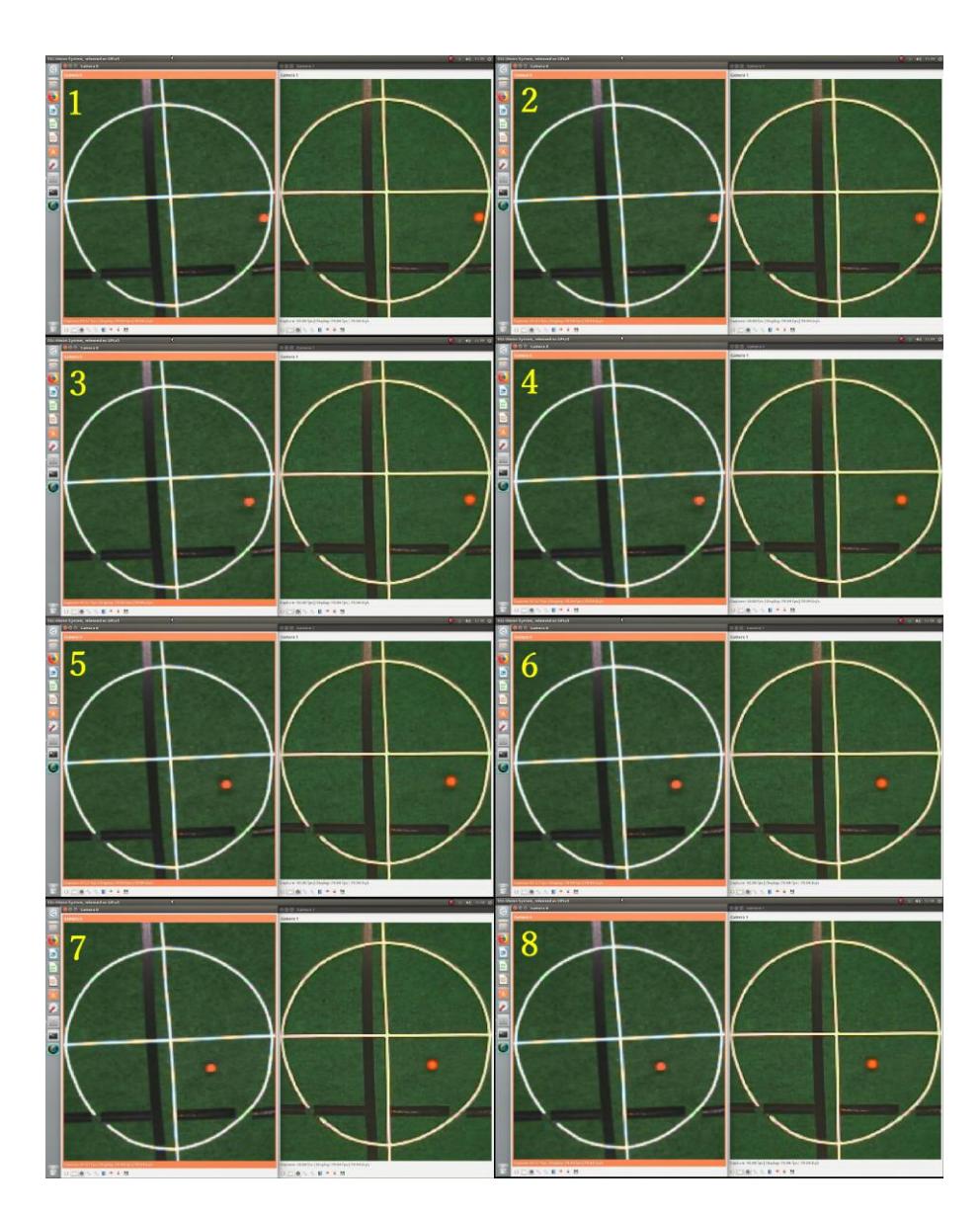
Furthermore, similar experiments were carried out under the condition that the two cameras are connected to the same desktop PC listed in Table 3. The results are displayed in Fig.7. The numbered time-series captured imagery indicate STINGRAY F-046 on the left and Blackfly BFLY-U3-05S2C-CS on the right. The images from the cameras were captured at the monitor's native frame rate of 60 fps, but in SSL-Vision, the frame rate (fps) of the video camera decreases from maximum value to 30 fps or 15 fps as the number of cameras increases. In addition, since the images are updated alternately, that is, they are not updated simultaneously, it is difficult to strictly compare the data transfer rate. However, at least the USB3.0 camera and the IEEE 1394B camera seem to be transmitted at almost the same transfer rate on the same PC.
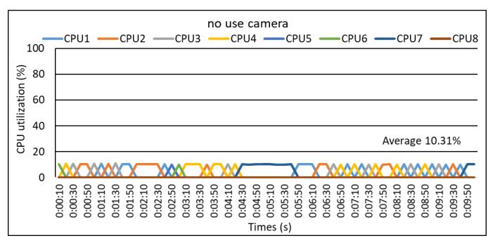
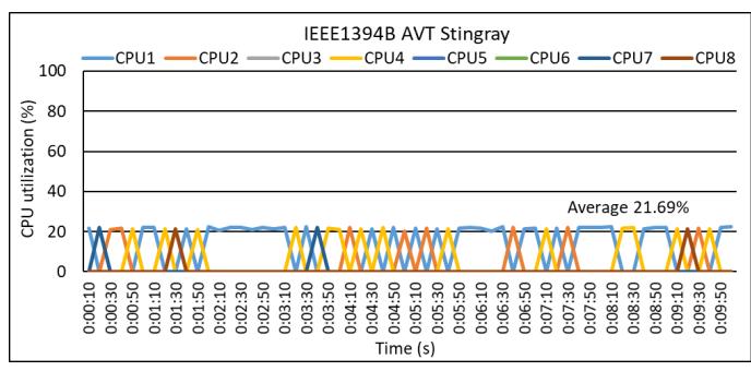
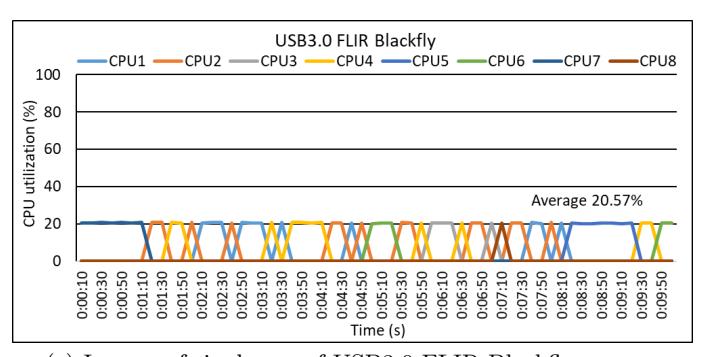
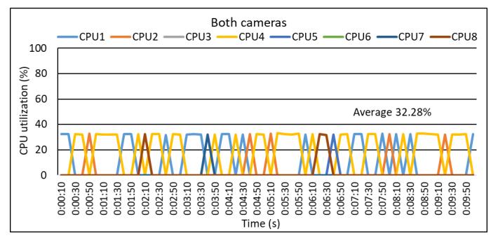
It was also investigated CPU utilization on PC by connecting one or both cameras. Figure 8 show the 10-minutes log data obtained every 10 seconds by pidstat command. In (a), it shows the result when no camera is connected. When one camera was connected, as shown in (b) and (c), the overall average of CPU utilization was increased by about 10% without dependence on the type of camera. The PC's load did not change even when adjusting the camera. In (d), it shows the results when both cameras are simultaneously connected. It is found that the load of each camera is simply summed up. Therefore, by increasing the number of USB3.0 cameras to four, PC capability is expected to be sufficient even in the official game environment. Of course, it is also possible to propose a good official environment by using a camera with higher resolution and frame rate. Anyway, based on above results, it may be said that there is no significant problem, even if the IEEE1394B camera is replaced to the USB3.0 camera.
![Fig. 4. USB3.0 camera (BFLY-U3-05S2C-CS[8]) used for evaluation](/tdps/soccer_smallsize__2019__KIKS/_page_4_Picture_5.jpeg)
Table 2. Specification of the cameras
| FLIR Blackfly(BFLY-U3-05S2C-CS) | AVT Stingray F046c | |
|---|---|---|
| Interf ace | USB3.0 | IEEE1394B 800Mb/s, 2ports, daisy chain |
| Image size | 808(H)×608(V) | 780(H)×580(V) |
| Sensor | Sony ICX693 | Sony ICX415 |
| Sensor size | Type 1/3 | Type 1/2 |
| F rame size | 50fps | 61fps |
| ADC | 12bit | 14bit |
| Image buffer | 16MByte | 128MByte |
| Bit depth | 8-24Bit | 8-14Bit |
| P ixel formats | Mono8,Mono12,Mono16, Raw8,Raw12,Raw16, RGB,YUV411,YUV422,YUV444 |
Mono8,Mono12,Mono16, Raw8,Raw12,Raw16, RGB8,YUV411,YUV422 |
Table 3. PC performance used in evaluation for cameras
| For USB3.0 FLIR Blackfly | For IEEE1394B AVT Stingray | |
|---|---|---|
| P C type | Laptop PC | Desktop PC |
| CP U | Core i7 7700H | Core i7 4790k |
| RAM | 16GB | 8GB |
| Mother board | N/A | ASUS H97M-E |
| OS | ubuntu 18.04 | ubuntu 16.04 |
| Host adapter | N/A(USB3.0) | FWB-PCIE-02 |
3 Software design
(Section content follows below in subsections)
3.1 Interpolation for stable motion of robot
In previous, our offense agent simply checked the data obtained from assigned robot and SSL-Vision and decided the action using that data. In this case, even if the robot disappeared for an extremely short time from SSL-Vision, a motion of the robot results to changing, and it cause a delay of the kick and a decrease of success rate of the pass-play. Therefore, we try to apply for the following processing and aim for stabilization of motion determination.
First, when the robot can be seen from SSL-Vision, our system receives the coordinate p, the speed v, and the time t at that time and updates it. That is, the elapsed time (means duration while a robot is observed) should be defined as d = (n - t) where n means the current time. Next, if data is not able to be receive from SSL-Vision, the coordinates are updated with p = p + v * d. In that case, while the elapsed time d is updated as same as the robot is visible, the speed v and the time t are not updated. Here, since the time to be considered is sufficiently short, it is assumed that the robots are moving at a constant velocity from previous position. Then, the coordinates p and velocity v are stored in an associative array using the robot ID as a key. If the elapsed time d is equal to or greater than a certain value, it is determined that the robot does not exist on the playing field, and the array element is deleted. Through the above processing, even if the data lack attributed to image processing for the robot's position in a very short time is caused, the influence on the strategy will be suppressed. By application of the state observer and/or the Kalman filter, it will be more accurate data.
3.2 Agent of offense
Role assignment When there are multiple robots assigned to the offense, each robot needs to play a variety of roles, not only to chase the ball. For example, a robot must wait for a pass or assist getting a ball advantageously in cooperation with other robots. Thus, we introduced the following algorithm to give a role in appropriate allocation corresponding to the situation.
First, the situation is evaluated from the ball possession and the position of the robots of both teams. Next, depending on the circumstances, candidates of positions to shoot or receive the passed balls are presented. The actions of each role are shown as follows.
Chaser Follow the ball and kick towards the given target position.
Follower Follow the ball with chaser
Receiver Depending on the situation, wait for the ball at the indicated position.
For these roles, allocation is determined by the following equations.
chaser_num = 1;
follower_num = ball_score < 0 ? 1 : 0;
receiver_num = visible_robot_num - follower_num - chaser_num;
if (wait_pos_num < receiver_num)
  follower_num += receiver_num - wait_pos_num;
where, ball score represents the ball possession, and when it is less than 0, the enemy team has a higher possession. And chaser num, follower num, receiver num, visible robot num, and wait pos num show the number of chasers, the number of followers, the number of receivers, the number of robots that can be used as offense, and the number of waiting positions, respectively. One robot is basically assigned as chaser. If the enemy team is in advantageous situation about the ball possession, one follower will be assigned. All of remaining robots are assigned as receivers, but if the number of receivers is more than number prepared as a standby position, the robots could not be receiver, and will be added to the follower.
Action decision algorithm for chaser When the robot (chaser) holds the ball, there are several candidates such as shoot and pass for the next action. In previous strategy, the robot just executed the pass according to a predetermined rule. However, with this method only monotonous operation is possible, it is difficult to properly respond to every situation occurred during the game. Therefore, we investigated an algorithm that selects the actions that will give the best results in future by searching the success probability of each action in each state and a tree recursively connecting it. In this algorithm, it is necessary to accurately estimate the success probability of each action in each state, and we have already reported in last our TDP[2] that prediction of shoot success rate by SVM (Support Vector Machine) will be effective. This method is also able to apply to the actions that pass the ball by adjusting the learning data and targets. The algorithm using this machine learning model is shown below. P(st, at) is defined as a success probability for actions such as at1,at2,,, which can be selected in state st of machine learning model at the time T. Then, evaluation value VT , which depends on the behaviors until the time T, is calculated by using P(st, at), the reward Rt, and the loss Lt.
$$V_T = \prod_{t=1}^{T} P(s_t, a_t) \sum_{t=1}^{T} \gamma^{t-1} R_t - \sum_{t=1}^{T} ((1 - P(s_t, a_t)) \gamma^{t-1} L_t)$$
where, the first term of the right side represents the expected value of the reward up to the time T, and the second term represents the sum of expected values of losses at each node. We choose the action whose evaluation value VT will be maximum in future. Rewards and losses are weighted, and high values are given to the actions that earn rewards in a shorter process. The risk management is also carried out by considering loss as well as rewards.
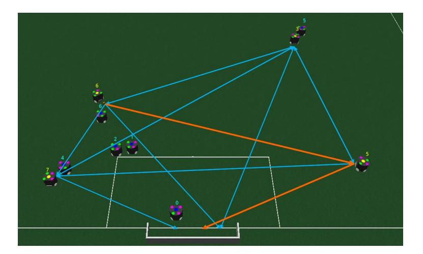
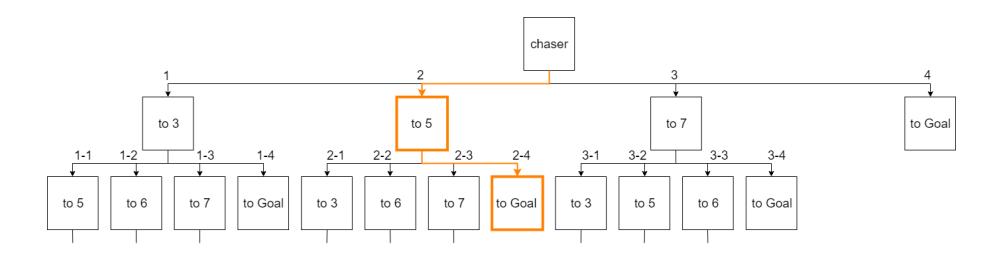
As an example, we consider the situation as shown in Fig.9. In this case, tree with multiple actions shown in Fig.10 are generated, and the evaluation value VT by eq. (1) becomes the maximum in the route indicated by orange color. Therefore, the path to robot #5 is selected. We know that the robot #5 will try to shoot the ball towards the goal at the next step, so one touch play is possible. In this algorithm, it is a problem that the computational complexity is increased compared with previous method(using simple condition analysis). SVM is essentially used for classification. So, additional processing is required for probability estimation. In addition, the computational complexity for the search of the game tree is also determined by its depth and the number of selectable actions. We are developing a client server model proposed in 2016TDP[9] to cope with the increase of computational complexity. As a further solution to this problem, we will study a method to cut the branches of tree structure effectively . Furthermore, it is a problem that the action selection depends on the learning data. For example, it is difficult to take a flexible approach to teams that have unexpected mechanisms or can execute strategic analysis. One solution to this problem is to activate the learning function during the game and to introduce the ϵ-greedy method with adjustment of ϵ that gives randomness of action selection[10],[11].
3.3 Dynamic assignment of the number of robots to agents
In previous, we prepared three agents, i.e., FORWARD, MARKING and DE-FENSE in the strategic program, and determined the number of robots for each agent, but did not change the number of robots according to game situation. For example, there were two robots placed in front of the home goal in the situations where it is no need to defend, on the contrary, there was a situation that robots keep on moving and waiting as the offense while enemy attacked. Therefore, in accordance with the situation of the game, the class is prepared to dynamically assign agents to each robot. We consider the following items as conditions to be assigned to agents.
- (1) How many enemy robots are in each area after separating fields in several areas
- (2) Position, trajectory, velocity of the ball
- (3) Information from SSL-Refbox, AutoReferee, SSL-Game-Controller (for example, last command, score, time to end etc)
- (4) Number of ally robots, performance for each robot
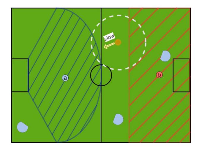
So, we try to determine the priority of the agent in game situation. It will be processed about the conditions (1) and (2) as follows. For the conditions (1), we divided the areas as shown in Fig.11. The left half area represents the area of our team, the hatched area ⓐ with blue color indicates an area where the enemy may shoot, and hatched area ⓑ with red color indicates the area where the opponent may defend. The blue circle indicates the position and orientation angle of the enemy robot, and the orange circle shows the ball. Taking into account the number of enemy robots in area ⓐ, determine the number of robots to defend. If there are many enemy robots in area ⓑ, the number of robots participating in the attack is increased. For the condition (2), for example, if the ball is on our side and near the enemy robot, it will not raise the priority of attack. That is, if the ball is moving with high speed and toward the our goal, the number of defense robot is increased. Therefore, according to above decision method, the number of attack robots will be increased in the situation of Fig.11.
The advantage of using the situation judgment class is that it will be able to use about decisions for the pass courses of a ball, and for the position of the defender and marker, because it observes and updates information of the entire field area. On the other hand, there are demerits that the parameters used to determine priorities are now adjusted by the hands, and also depends on experiences of the person. It is necessary to consider introducing reinforcement learning etc. to obtain appropriate values hereafter.
References
- [1] Koh Ohno, Toshiki Mimura, Hayato Yokota, Tessen Ohmura, Tetsuya Sano, Masato Watanabe, and Toko Sugiura: KIKS 2017 Team Description, https://ssl.robocup.org/wp-content/uploads/2019/01/2017_TDP_KIKS.pdf (2017).
- [2] Toshiki Mimura, Koh Ohno, Hayato Yokota, Satoru Nakayama, Masato Watanabe, and Toko Sugiura: KIKS Team Description for RoboCup 2018, https://ssl.robocup.org/wp-content/uploads/2019/01/2018_TDP_KIKS.pdf (2018).
- [3] J. Almagro, J. Feltracco, R. Medrano, S. Naeem, J. Neiger, R. Osawa, E. Peterson, A. Shaw, M. Woodward: RoboJackets 2018 Team Description Paper, https://ssl.robocup.org/wp-content/uploads/2019/01/2018_TDP_RoboJackets.pdf (2018).
- [4] Makito Ishikura, Ryo Itohara, Tomoaki Tsuchie, and Kazuhiro Fujiwara: MCT Susanoo Logics 2013 Team Description Paper, https://ssl.robocup.org/wp-content/uploads/2019/01/2013_TDP_MCT_Susano_Logics.pdf (2013).
- [5] A. Boussicault, P. Felix, L. Hofer, O. Ly, S. N 'Guyen, G. Passault, A. Pirrone: AMC Team Description Paper Small Size League RoboCup 2018 Application of Qualification in Division B, https://ssl.robocup.org/wp-content/uploads/2019/01/2018_TDP_AMC.pdf (2018).
- [6] Lingyun Chen, Lisen Jin, Cheong Weng Lon, Licheng Wen, Jianyang Gu, Jiacheng Li, Tianqing Fang and Rong Xiong: ZJUNlict Extended Team Description Paper for RoboCup 2018, https://ssl.robocup.org/wp-content/uploads/2019/01/2018_ETDP_ZJUNlict.pdf (2018)
- [7] https://github.com/RoboCup-SSL/ssl-vision/wiki/requirements
- [8] https://www.ptgrey.com/blackfly-05-mp-color-usb3-vision-sony-icx693
- [9] Tatsuro Sakaguchi, Koh Ohno, Toshiki Mimura, Naoki Tanaka, Kenta Satoh, Yu Yamauchi, Yoshimasa Nagasaka, Masato Watanabe and Toko Sugiura: KIKS 2016 Team Description, https://ssl.robocup.org/wp-content/uploads/2019/01/2016_TDP_KIKS.pdf (2016).
- [10] Sutton, R.S., Barto, A.G.: Reinforcement Learning: An Introduction. MIT Press, Cambridge, MA (1998).
- [11] Watkins, C.: Learning from Delayed Rewards. PhD thesis, University of Cambridge, Cambridge, England (1989).