KgpKubs 2019 Team Description Paper
Ashish Gaurav, Tanishq Jasoria, Shivam Kumar Panda, Pranit Dalal, Himanshu Mittal, Sayan Sinha, Saurabh Agarwal, Rahul Kumar, Rajat Kumar Jenamani, Prashant Ramnani, K Snehal Reddy, Manjunath Bhat, Vishal Raj, Shamin Aggarwal, Aniruddha Kirtania, Gopi Reddy Chilukuri, Murli Kartik, Aditya Agrawal, Anirudh Roy, Anjaneya Praharaj, Jasmine Jerry, Pravartya Dewangan, Arpit Dwivedi, Dileep Pavan Surya, Rajdeep Mondal, Dewansh Raj, Chitrang Garg, Abhinav Gupta, Sudeep Sharma, Mayank Bhushan, Sudarshan Sharma, Ankush Roy
Indian Institute of Technology, Kharagpur West Bengal, India
Abstract This paper describes the mechanical, electronic and software designs developed by Kharagpur RoboSoccer Students' Group (KRSSG) team to compete in RoboCup 2019. All designs are in agreement with the rules and regulations of Small Size League 2019. Software Architecture implemented over Robot Operating System(ROS), trajectory planning and velocity profiling, dribbler/kicker design and embedded circuits over the last year have been listed.
1 Introduction
KgpKubs is a RoboSoccer team from IIT Kharagpur, India. The research group aims to make autonomous soccer playing robots and participate and conduct various related events. Undergraduate students from varied departments and years are a part of this group. We have previously participated in FIRA RoboWorld Cup in the years 2013-2015 in the Mirosot League and secured Bronze Medal in the same in 2015. We have also participated in RoboCup SSL & 3D-Simulation League in Nagoya, Japan 2017. In June 2018 we participated in RoboCup 3D-Simulation League in Canada.
This paper is a continuation of last year's Team Description paper and describes the developments made after last year's participation. Mechanical design of the robots is presented in section 2. The firmware and embedded circuits are described in section 3, followed by the software system in section 4. Finally, the discussion and future work are described in section 5.
2 Mechanical Design
The robots are designed in Solidworks. Most of the static simulations were done extensively using Ansys (Workbench) whereas for dynamic simulations we used Adams.
The current robot chassis is manufactured using Aluminium 6061 to ensure the strength of the robot and keep it low weight. But we are looking forward to a new version of bot whose chassis will be manufactured through FDM technique (discussed in section 2.4). All the electrical components are organized in a housing compartment which ensures safety and accessibility inside the robot. Table 1 summarizes hardware configuration of the bot.
Robot Hardware
| Dimensions | Dia: 179mm , Height: 149mm |
|---|---|
| Driving motors | Maxon EC-45 Flat (50W) |
| Gear Type | Internal Spur |
| Gear Ratio | 1:3.3 |
| Wheel diameter | 50mm |
| Dribbling motor | Maxon EC-16 (30W) |
| Dribbling gear Ratio | 9:11 |
| Dribbling bar diameter Dia: 14mm | |
| Max. ball coverage | 19% |
| Sub-wheel Diameter | 10mm |
2.1 Locomotion System
The drive system is a four-wheel omni-drive with the rear wheels inclined at 90 degrees and the front wheels inclined at 120 degrees to provide space for the dribbler and kicker mechanism. This time we are using a different motor, Maxon EC45 flat (50W), which provides some space between the motor and the middle plate. Spur gears are used between wheels and motors with a gear ratio of 1 : 3.3.
2.2 Dribbling Mechanism
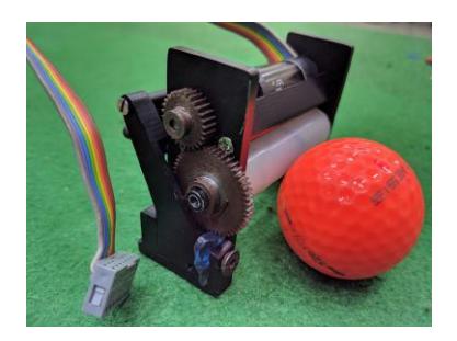
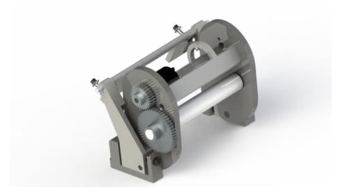
The new dribbler design would be used this year. The four bar constrained mechanism with linear damping, as mentioned in KGPKubs TDP 2018[13]. This dribbler helps for two purposes:
- Adjusting the best height for efficient dribbling of the ball without any slipping between the dribbler rod and the ball.
- The linear damping ensures a decent range of forward and backward acceleration without stalling the dribbler as well as without toppling the bot.
According to the dynamical equations formulated for the active handling of the ball and the best range of accelerations were obtained from $-3m/s^2$ to $+3m/s^2$. The best range of height for the dribbler rod from the ground is between 27.3mm to 29.3mm. Additionally, The best range of angles is from 0° to 20°. All the results were obtained by carrying out analysis in MATLAB. Simultaneously, the analysis for the gears provided best gear ratio with the motor Maxon EC16 30W and gear-box is 4.4 : 1 which is 9 : 11. For the dribbler material, silicon rubber has been used.
Few more changes have also been added to the existing design to facilitate the chip plate, IR sensor and to stop the ball from escaping while the bot rotates.
Apart from that, we are changing the surface profile of the dribbler rod by introducing concavity. This concavity will facilitate self centring of the ball while the bot moves or rotates. The equation for the concavity was designed using cubic spline where we applied certain boundary conditions, our required conditions of no slipping and a range of angular acceleration of the bot within which the bot holds the ball.
The latest design of the dribbler will be implemented before RoboCup 2019 as shown in Fig.1(b) .
2.3 Kicking Mechanism
Straight Kicker
The straight kicker is powered by two 250V 2200uF capacitors, which can be charged by a step-up converter to 200V each. In the earlier design, we had cylindrical solenoids made of 6061-Aluminium alloy. It had windings of 23AWG copper wire and 680 turns. The straight kicker hits the ball at 2R/3 (height from the ground) in order to obtain the optimum velocity. The new anodised plunger and a 3D printed solenoid would prevent any short-circuiting problems which used to happen.
Solenoid Optimization
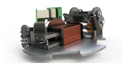
The optimised rectangular solenoid mentioned in KGPKubs TDP 2018[13] is being used. It facilitates both the straight kicker and the chip kicker within the available space in the bot. The outer dimensions were decided by maximising the volume of solenoids within the available space. Optimization of the inner dimensions was carried out by implementing Finite Element Analysis using MATLAB such that maximum flux should pass through the solenoid. The maximum flux is found for l × b × h = 56mm × 40mm × 18mm Further, the thickness of the winding layers is 3.4mm which sets the inner dimensions of the solenoid.
Chip Kicker
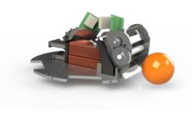
This year in RoboCup 2019, KGPKubs will be playing with chip kickers. The implementation of two rectangular solenoids helped in facilitating the chip kicker. This section discusses about the design and development of the chip kicker in our SSL bot.
The designing of the chip plate on the front was the main challenge in modelling the chip kicker. The design parameters included height of the hinge of chip plate, front angle and moment of inertia of the chip kicker.
The dynamics model of the chip kicker was formulated accordingly and analysed in MATLAB by varying the parameters, considering Aluminium 6061 as the material. According to the calculations, the velocity of the ball on chipping increased with its moment of inertia which provided larger range and height to the ball. Hence certain design modifications were attained in that direction.
The optimum height and range was obtained in MATLAB with a chip plate front angle 45 degrees with horizontal. However, considering the rotation of the ball due to the dribbler while chipping, the optimum angle would be more than 45 degrees (with horizontal). According to the calculations, the optimum height and range of the ball on chip kicking obtained are 50cm and 140cm respectively.
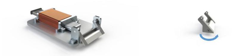
However to validate the calculations we needed to carry out experiments for variable chipping angle. Hence we designed an experimental setup with rectangular solenoid and variable angle chip plate. The variable angle chip plate facilitates changing the front angle. Hence the experiments could be done at various angles and accordingly the optimum angle could be obtained experimentally.
The range and height of the ball while chipping can be varied by changing the kicking speed and rpm of the dribbler. Hence the relations obtained from the calculations can be used to chip and pass the ball over the required distance and height. Currently, the chip plate with a front angle 45 degrees is implemented. The accurate angle obtained from the experiment will be implemented before RoboCup 2019.
2.4 3D Printed Chassis
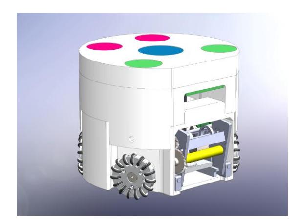
Our team is working towards changing the complete chassis of the bot. Currently, the whole chassis is made of aluminium. This increases the cost of the bot and also causes shorting problems if not properly insulated. Hence, the whole chassis of the bot has been designed again considering it would be completely 3D printed. The chassis is divided into two parts - the base would include the straight and chip kicker, dribbler and battery, while the upper circuit holder would contain all the embedded components. It would further decrease the weight of the bot to around 2kg from currently 2.7kg. 3D printing the chassis would make it more customizable and the design can be easily changed and manufactured at lower costs.
Other advantages include easier assembling and disassembling of the bots, lowered centre of mass of the bot and no short-circuiting issues.
We are fabricating the chassis with PLA material using FDM 3D printing technique. After properly analysing and validating the feasibility of the chassis we will be implementing it in our final bot for RoboCup 2019.
3 Embedded Systems
3.1 Main controller board
Xilinx Spartan 6 is used as the central processing unit which controls four base motors, dribbler and other peripherals. The communication between the main board and the central server is established using Microchip ESP32 WiFi modules. For accurate kicking, IR obstacle sensor module has been used to sense the appropriate location of the ball before kicking. Lithium Polymer (Li-Po) over discharge protection circuit is incorporated in the main circuit.
3.2 Motor Controllers
Even after trying out various architecture listed below, we were not able to make an efficient motor controller.
- Architecture 1 Single microcontroller is used for both speed calculation and control loop implementation. In this architecture, the system is heavily loaded, and it degrades the performance, destabilising the control loop at higher speed.
- Architecture 2 A separate microcontroller is used for speed calculation, the load on the central microcontroller is divided thereby making it possible for the system to control the motor for higher speed. The slave microcontrollers communicate with the master (central) microcontroller using UART communication protocol. The overhead caused due to this communication comes into action when target speed is above around 75% of the maximum speed, and the control loops become unstable.
So we finally shifted our motor controller to an FPGA based architecture. When an FPGA is used as the motor controller, parallel processing is exploited, and the system becomes capable of reaching maximum possible speed for the motors (capable of handling the ticks at maximum 6MHz).
We were successful in developing motor controller based on Hall Sensors feedback on Xilinx Spartan 6. The efficiency and reliability of this controller are far better than the one implemented on a microcontroller. We have also implemented PID closed loop on FPGA using quadrature encoder feedback from the motor. Using FPGAs, we can control all the five motors with PID closed loop implemented efficiently, even at high speeds without any issues.
Last year, ESCON 24/2 motor drier module was used to control the BLDC motors in our robots. These controllers come with a dedicated control circuit to drive the motor along with great error detection capabilities. The driver threw much error and was not much reliable for the dynamic gameplay involved in Small Sized League.
To overcome these problems, we designed our motor drivers using IR4427, IRF7389 and control logic through FPGA. IR4427 is used as the gate driver in the current motor driver circuits. It is a low voltage, high-speed power MOSFET and IGBT driver. The output drivers feature a high pulse current buffer stage designed for minimum driver cross-conduction. Propagation delays between two channels are matched. IRF7389 is an Ultra Low-On resistance MOSFET IC. This benefit, combined with fast switching speed and ruggedised device design provides the designer with extremely efficient and makes it a reliable device.
At first, the module was not reliable due to high power consumption. However, over the year we were able to optimise the power consumption by altering passive components in the circuit. Now we have an extremely efficient and robust motor controller module.
3.3 Communication Module
Till last year we are using the nRF24L01+ wireless module from Nordic Semiconductor for our communication. Quite many problems were faced during the testing phase and in the previous participation at RoboCup 2017. Its range and Line-of-Sight communication characteristic posed a massive problem for us. Its power output is also low which causes problems in long-range communication. Its air data rate is only 2Mbps which was very low for our operations and bidirectional communication between bots and the server.
Ultimately we decided to use ESP32 WiFi module by Microchip. ESP32 is a low-cost, low-power system on a chip (SoC) series with Wi-Fi dual-mode Bluetooth capabilities. At its heart, there's a dual-core Tensilica Xtensa LX6 microprocessor with a clock rate of up to 240 MHz. It is highly integrated with built-in antenna switches, RF balun, power amplifier, low-noise receive amplifier, filters, and power management modules. Air data rate of ESP32 is more than 32Mbps which helps us in establishing a bidirectional link between our bots and the server. Its dual-core, 240 MHz microcontrollers can be used as a co-processor with FPGA.
The only problem with this module is that it works on the 2.4GHz spectrum, which can cause interference in communication and lead to data loss. We are working on avoiding the problem of interference by various methods like identifying and selecting the least crowded channel for communication. Moreover, we are planning to develop a mesh network of the six bots and the central server.
3.4 Kicker Board
The kicker board constitutes of a charging and a discharging circuit. The FPGA on the main circuit is controlling the circuit. The board receives charge trigger and kicking level from the main circuit, charging the capacitor bank of 4400uF to 250V using flyback topology.
Charging Circuit
Our charging circuit is based on LT3750, a flyback converter designed to charge large capacitors to a user-adjustable target voltage rapidly. It consists of a different resistor which can be used to change various output parameters like charging current. The CHARGE pin one the IC gives full control of the LT3750 to the user and the DONE pin indicates when the capacitor has reached its programmed value, and the part has stopped charging. It also has features like under voltage lockdown and overvoltage protection.
The new charging circuit is significantly small in size and much more robust and faster than the previous circuits. It charges the capacitor bank of 4400uF up to 250V in just 4 seconds while the earlier circuit took more than 10 seconds to perform the same task.
Discharging Circuit
Earlier we used relays for discharging capacitors through a solenoid. Since ON/OFF delay of the relay is ¿100ms, it is not possible to implement variable discharging of capacitors using relays. So we switched to IGBTs for the purpose as they have high current ratings, switching losses are minimal, and their switching speed is optimal for implementing the variable discharging module. We have successfully implemented a fully functional variable discharging module using IGB50N60T(IGBT) and HCPL-3120(Optocoupler). Current module is capable of discharging at a maximum current of 20A, which is suitable for both straight and chip kicking.
4 Software
The following section has the description of the developments and changes made on the software side, since our last participation in SSL. An overview of Finite State Machine (FSM) architecture developed on Robot Operating System (ROS) is presented in subsection 1. Subsection 2 describes the structure of basic behaviors, subsection 3 discusses the integration of chip kicking in software, subsection 4 discusses development in GUI. Subsection 5 describes the role assignment module used for optimized assignment of roles in between different robots. Subsection 6 describes the improvement in path planner.
4.1 Code Base
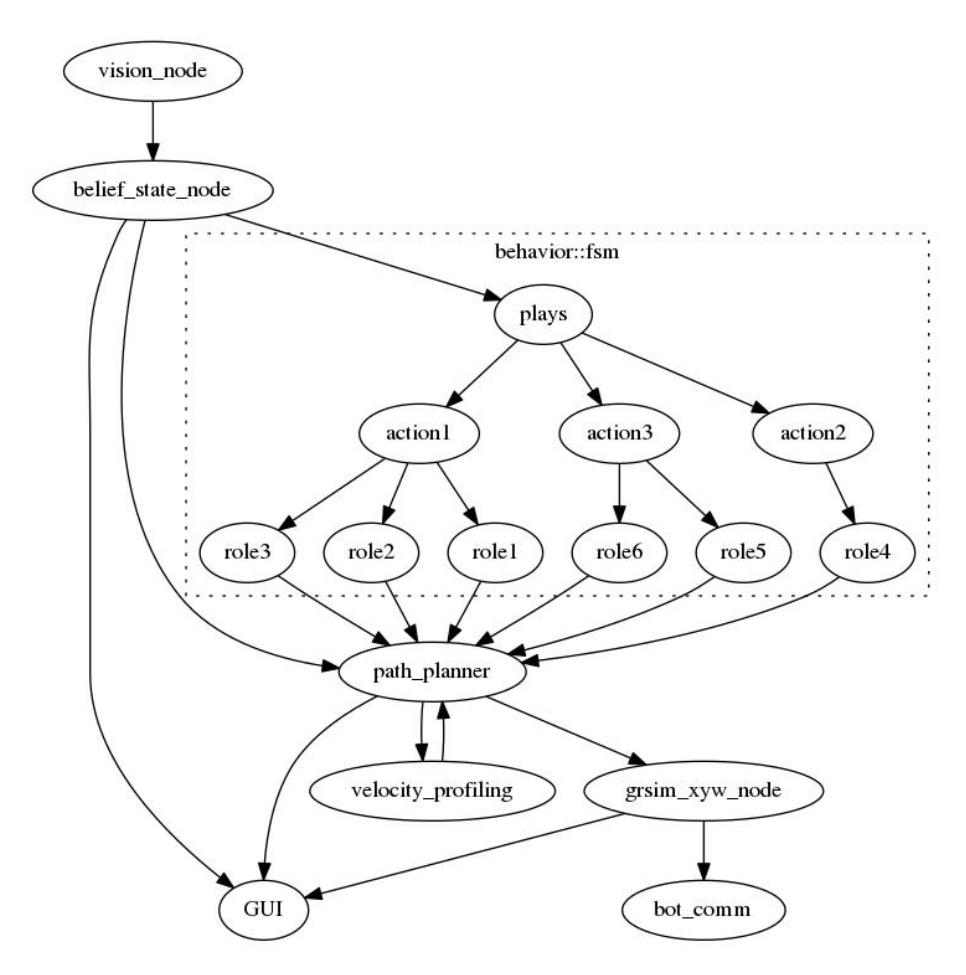
In this section, we describe the structure of our code-base. Last year, we started to shift our code-base from skills-tactics-plays (STP) architecture to Finite State Machines (FSM) architecture. Our code base is based on Harel State Machines [19], making particular use of hierarchy, parallelism and broadcasting.
Hierarchy: Our software relies on a generic hierarchical state machine class in which a state comprises of sub-states. Each state is implicitly in its parent state, thus sufficing the polymorphism of state machines.
Parallelism: We have a separate FSM to control the goalie which runs in parallel to the code base. The goalie is dependent on the current states of the code base, and the required information is shared using broadcasting.
Broadcasting: There is often a need to broadcast data from one state to the others in order to facilitate parallelism, especially the goalie. Moreover, real time position of the robots is an input shared across all states. The data is broadcast from another state which runs in parallel, handling the I/O.
4.2 Behaviours
This section describes the FSM architecture of behavior which will act as low level of our code base. We describe two behaviours which are integral for RoboSoccer and have noticed significant changes compared to the architecture last year.
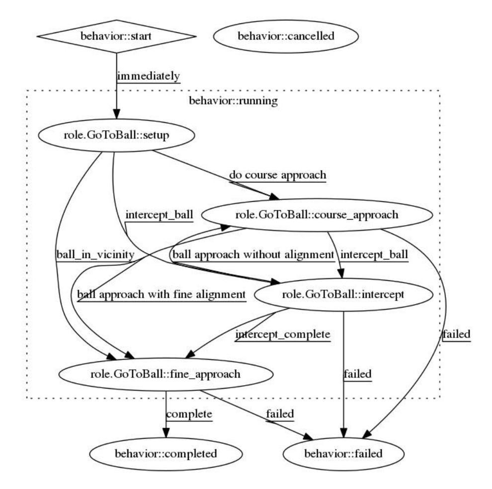
GoToBall GoToBall is one of the most fundamental functionalities in RoboSoccer. We have implemented GoToBall using the FSM architecture. (See Fig. 6)
- Setup: Setup indicates the beginning of the GoToBall role. In this state conditions are checked which is used to decide which state to transition to.
- Course Approach: In this state, the bot approaches the ball (without aligning towards a particular angle) using the RRT Connect algorithm and a trapezoidal velocity profiler.
- Intercept: This state is transitioned to, when the ball is moving and has significant velocity. We predict the ball's trajectory based on its current position and velocity and sends the bot to intercept it.
- Fine Approach: This state is transitioned to when the bot is in close vicinity of the ball but not yet reached it. In this state, the bot aligns itself towards the ball and engages it with the dribbler.
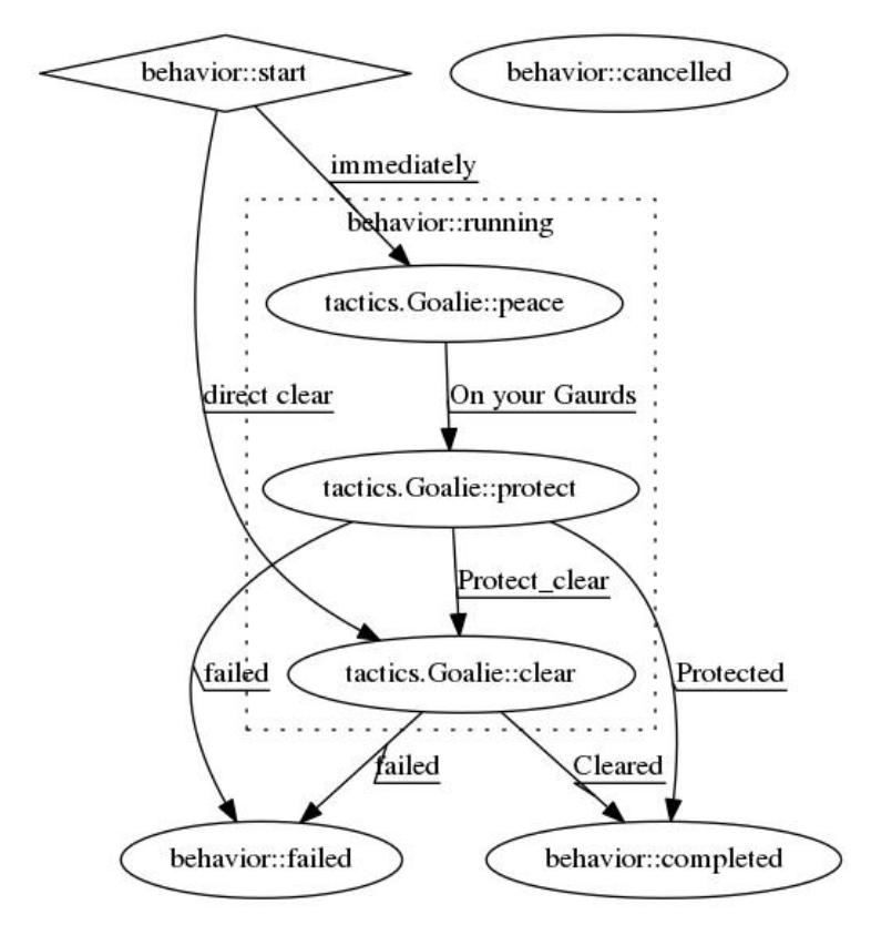
Goalie The Goalie has 3 states (Fig. 7):
- Peace: This state is transitioned to when the ball is in the opponent's half. In this state, the Goalkeeper is following the ball's y-coordinate.
- Protect: This state is transitioned to when the ball is in our half but not in the D-box. In this state, the Goalie aligns itself towards the ball and we predict the ball's trajectory and position the Goalie to intercept it at the goal line.
- Clear: This state is transitioned to when the ball is in our D-box. In this state, the Goalie goes to the ball and kicks it towards the opponent's goal.
4.3 Chip Kicking
This year, for the first time, we have implemented chip kicking into our SSL bots. Accordingly, we have incorporated the feature in our software as well. The model by and large tries to predict the occurrence of a chip kick from the trajectory of the ball. The trajectory is denoted by the position of the ball (x and y coordinates) at equal intervals of time. The prediction also requires information about the grid from which the ball originated.
Data preprocessing
The generation of input features for the model can be thus summarised as:
- Trajectory Generation: The position of the ball at equal intervals of time is demanded as an input feature to our model. The position information obtained from the vision node is over UDP, hence in general, not only there is lack of guarantee of the data being sent at equal time intervals, but also that the data is arriving sequentially. Converting to a TCP architecture would solve the second issue, but would introduce unnecessary overhead. Moreover, introduction of TCP would require changes in certain key components of the SSL software
architecture. Hence, instead we made use of the timestamp to the data being received. In order to make sure the data used to generate the trajectory is at equal intervals, we fit a polynomial curve to the data received and try to predict the coordinate placed at equal intervals. We do this using the Savitzky Golay filter, fitting a polynomial of degree seven to each of the coordinates, and predicting the position at equal time intervals.
- Grid information: We divide the entire field into a set of hexagonal grids. We keep the hexagonal grids mapped based on their distance from the camera. Hexagons ensure most efficient packing in 2D space and are quite popular in the domain of robotics [18] [20].
Model
Our model features a deep neural network consisting of the following:
- Fully Connected Networks: In a fully connected network, each neuron is connected to every neuron in the previous layer. This is a totally general purpose connection pattern in an artificial neural network.
- LSTM: In a recurrent neural network (RNN), a directed graph along a sequence is formed from connections between nodes. Long Short Term Memory networks [21] (LSTMs) are a special kind of RNN, capable of learning long-term dependencies and extending their memory.
Model architecture
Our model features an LSTM layer followed by two fully connected layers. We made use of Binary Crossentropy Loss, with RMSprop as an optimiser.
The first Fully Connected layer takes as input the output from the LSTM model and the distance of the grid from the camera. It is followed by selu activation and a dropout with probability 0.35.
Model architecture:
| Layer number | Layer Type | Input Shape | Output Shape |
|---|---|---|---|
| 1 | LSTM | (None, 150, 50) | (None, 64) |
| 2 | Fully Connected | (None, 66) | (None, 256) |
| 3 | Fully Connected | (None, 256) | (None, 2) |
Results
We obtained an overall accuracy of 0.67 in chip prediction, with a recall of 0.63. We hope to improve upon the accuracy using further experimentation in the future.
4.4 GUI Development
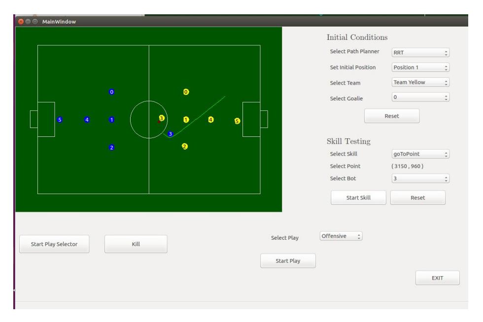
We developed a PyQt based GUI that provides a graphical visualization of the data obtained from vision/grSim (Fig. 8).
This GUI can be used for testing skills such as GoToBall and GoToPoint and, displays the correct state of the field and the respective paths planned for different bots using RRT connect algorithm. This is achieved by using multithreading to display the various paths being simultaneously planned for different bots. This makes it simple and time efficient to monitor and correct the errors.
Features:
- Can be used to test Basic Skills
- Shows the respective paths planned using RRT Connect for each bot using multi-threading.
4.5 Role Assignment Module
We use a Role Assignment Module for automatic allocation of tasks to available bots in a dynamic soccer game environment. We have a fixed set of tasks and each of them is related to a point on the actual field. Using the current game state, we then assign each bot a task. This results in the automatic assignment of agents to tasks, avoiding situations where missing agents might be assigned with tasks. Due to the resulting optimal agents-tasks assignments, the distance travelled by each agent is the lowest possible.
The module has two major components, namely Analyzer Module and Role Assignment Module. Analyzer analyses the current game state and the available agents, together with their locations and decides which tasks are to do be done and the subset of agents that will participate in the assignment.
The role assignment module receives such information and outputs an assignment of agents to tasks such that the agents have to move minimum distance to implement the task using a cost function. The cost function used by my team is influenced by the Min-Max Algorithm
The role assignment module takes in the input from the former module and then maps each bot in the subset of bots which it received to the tasks which are to be performed making sure that the agents have to move minimum distance to implement the task using a cost function. The cost function is leveraged through the Hungarian Algorithm.
The set of tasks we have defined are:-
- ∗ Defender Defender remains close to the goal of the opponent (precisely beyond 3/5th of the lenght of the field) in order to protect the ball from approaching opponent's goal. It is positioned using a probability given to various grids on the field.
- ∗ Supporter Supporters position themselves in order to easily receive pass.
- ∗ Attacker In case it is able to shoot to a goal, the attacker does so. Otherwise it passes the ball to a better attacker.
- ∗ Clearer When the defender begins to take care of the approaching ball, the clearers position themselves to receive pass and bring the ball back to attacker's paradise.
- ∗ Obstacles In case the game goes out of hand, the obstacles try and block the opponents from approaching the ball. The game play takes up a more defensive approach.
4.6 RRT* APF
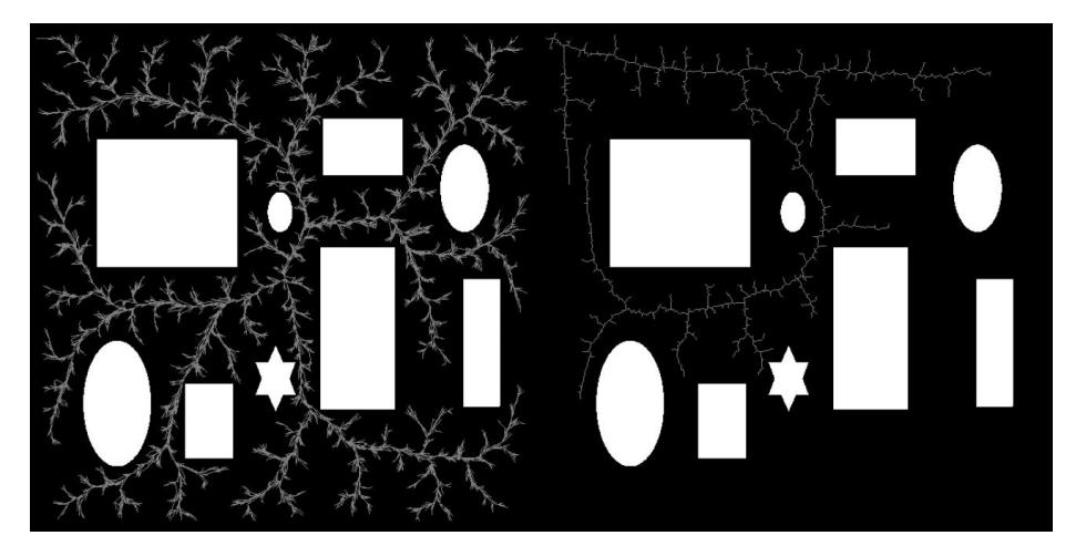
We improved the standard RRT-star algorithm using the concept of artificial potential field. An attractive field is assumed originating from the destination and repulsive fields are assumed at each of the obstacles and this results in the path converging more towards the target point. We rigorously tested and fine tuned the constants for the potentials.
5 Discussion and Future Works
As future work, it is imperative to explore more dynamics that affect the robot behaviour.
5.1 Model Predictive Control
In our current model,we do not consider the effect of the current independent variables on the future. This may also create problems in input and output constraints. So we plan to use model predictive control to overcome these problems. We send velocities to the bots based the current state without much consideration of the future currently. We plan to see the effect of the velocities before sending them by checking its effect using an appropriate cost function. We then plan on finding cost minimizing control strategy (solving Euler-Lagrange equations) and then sending them.
5.2 Embedded Systems
On the embedded side, we aim to develop mesh network of the bots to avoid data loss and increase the range of communication; develop fuzzy-PID controller based on encoder readings on FPGA; integrate IMU for better state estimation;
Acknowledgements
The team also acknowledges the mentorship and guidance of our professors Prof. Jayanta Mukhopadhyay, Prof. Sudeshna Sarkar, Prof. Alok Kanti Deb and Prof. Dilip Kumar Pratihar. This research is supported by Sponsored Research and Industrial Consultancy(SRIC), IIT Kharagpur. We also thank our former team members who made all of this possible.
References
- Brett Browning, James Bruce, Michael Bowling, and Manuela Veloso. Stp: Skills, tactics, and plays for multi-robot control in adversarial environments. Proceedings of the Institution of Mechanical Engineers, Part I: Journal of Systems and Control Engineering, 219(1):33–52, 2005.
- Tamas Kalmar-Nagy, Raffaello D'Andrea, and Pritam Ganguly. Near-optimal dynamic trajectory generation and control of an omnidirectional vehicle. Robotics and Autonomous Systems, 46(1):47–64, 2004.
- Michele Aicardi, Giuseppe Casalino, Antonio Bicchi, and Aldo Balestrino. Closed loop steering of unicycle like vehicles via lyapunov techniques. Robotics and Automation Magazine, IEEE, 2(1):27–35, 1995.
- Werner Dirk Jan Dierssen. Motion planning in a robot soccer system. A Master's Thesis, Language, Knowledge and Interaction Group Department of Computer Science University of Twente The Netherlands, 2003.
- Marko Lepetic, Gregor Klancar, Igor Skrjanc, Drago Matko, and Bostjan Potocnik. Time optimal path planning considering acceleration limits. Robotics and Autonomous Systems, 45(3):199–210, 2003.
- Christoph Sprunk and Boris Lau. Planning motion trajectories for mobile robots using splines. University of Freiburg, 2008.
- Gregor Klancar, Drago Matko, and Saso Blazic. Mobile robot control on a reference path. In Intelligent Control, 2005. Proceedings of the 2005 IEEE International Symposium on, Mediterrean Conference on Control and Automation, pages 1343– 1348. IEEE, 2005.
- Michael Bowling and Manuela Veloso. Motion control in dynamic multi-robot environments. In Computational Intelligence in Robotics and Automation, 1999. CIRA'99. Proceedings. 1999 IEEE International Symposium on, pages 168–173. IEEE, 1999.
- Alessandro De Luca, Giuseppe Oriolo, and Marilena Vendittelli. Control of wheeled mobile robots: An experimental overview. In Ramsete, pages 181–226. Springer, 2001.
- Oussama Khatib. Realtime obstacle avoidance for manipulators and mobile robots. The international journal of robotics research, 5(1):90–98, 1986.
- 2018 STOx's Extended Team Description Paper, RoboCup 2018 Symposium.
- Brett Browning, James Bruce, Michael Bowling, and Manuela Veloso. STP: Skills, tactics and plays for multi-robot control in adversarial environments
- KGPKubs Team Description Paper, RoboCup 2018 Symposium.
- RT-RRT*: A Real-Time Path Planning Algorithm Based On RRT*,Kourosh Naderi, et. al.
- ESP32 Datasheet, July, 2018. https://www.espressif.com/sites/default/files/documentation/esp32 datasheet en.pdf
- Spartan-6 FPGA Data Sheet. https://www.xilinx.com/support/documentation/data sheets/ds162.pdf
- Andre Ryll, Mark Geiger, Nicolai Ommer, Arne Sachtler, Lukas Magel. TIGERs Mannheim - Extended Team Description for RoboCup 2016, 2016
- Saurabh Agarwal, Ashish Kumar Gaurav, Mehul Nirala, Sayan Sinha. Potential and Sampling Based RRT Star for Real-Time Dynamic Motion Planning Accounting for Momentum in Cost Function, ICONIP 2018
- Harel D, Kugler H. Synthesizing state-based object systems from LSC specifications. International Journal of Foundations of Computer Science. 2002 Feb;13(01):5-1.
- Sinha S, Nirala MK, Ghosh S, Ghosh SK. Hybrid path planner for efficient navigation in urban road networks through analysis of trajectory traces. In2018 24th International Conference on Pattern Recognition (ICPR) 2018 Aug 20 (pp. 3250- 3255). IEEE.
- Gers FA, Schmidhuber J, Cummins F. Learning to forget: Continual prediction with LSTM.