OMID 2019 Team Description
Ali Mollajafai, Mohammad hossein Zahedi, Alireza Fatollahzade, Rasoul Aboutalebi, Alireza Sahebi, Javad Rahmani, Omid Mahdizadeh, Yashar mahmoudi, Hashem Khan mohammadi, Mohammad hossein Zolfaghari, Maryam Akhoundian
Department of Electrical Engineering of Shahed University of Tehran, Iran; Department of Computer Engineering of Shahed University of Tehran, Iran; Department of Biomedical Engineering of Shahed University of Tehran, Iran; Department of Computer Science of Shahed University of Tehran, Iran; Department of Electrical Engineering Islamic Azad University Science and Research Branch; Department of Electrical Engineering of Khaje Nasir University of Tehran, Iran
Abstract This paper is an explanation of recent technical improvements of OMID, a small size league team intending to participate in RoboCup 2019 in Sidney, Australia.
Introduction
Omid Robotics Team (ORT) began small size team in 2007. ORT has been participated in competitions since 2007 as a branch of robotics society of Department of Electrical Engineering of Shahed University located at Tehran, Islamic Republic of Iran.
This paper is focuses on two general section: electrical and software.
We used new encoders to improve controlling wheels speed. It explained in section 2.
Section 3 represents our new motion control system. Also it describes a method in our path finding system to find a path to an inaccessible destination. In addition, this section introduce our new decision layer system that let robots make smarter choices in game.
2 Electrical System
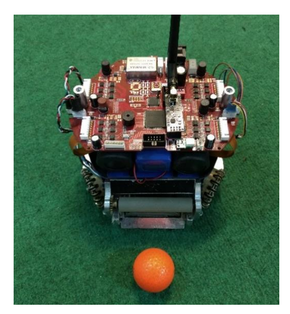
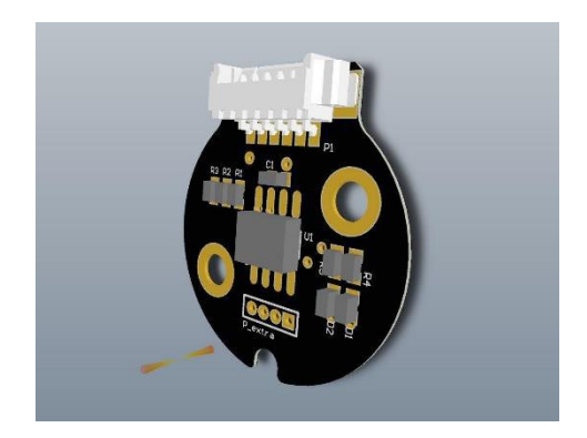
Last year major problems had been solved by designing new boards and they have worked properly without any problem through these years. Details of the designed board are shown in last year's TDP [1]. Furthermore, in recent structure of robots, magnetic encoders have been used instead of the optic ones to control wheel's speed better.
2.1 Magnetic Encoder
As magnetic encoders have higher resolution and not needing the motor back shaft, they have better performance compare to optic e4p encoders [2]. What is more, we saved a lot of money in providing the encoders themselves and motors by this alteration. Further explanation about these magnetic encoders are shown in Immortals team TDP [3].
3 Software
(empty)
3.1 Motion Control
In our last TDP, we discussed about PID as a controller of the robot's motion. We had some problems with this controller. For example, if a robot wants to go to the specified destination, it should moves at the maximum speed until a specified distance from destination which then the PID controls the speed of the robot, so the robot can reach the destination as fast as possible. But equalizing the maximum speed and the first generated speed of PID was difficult for us.
Therefore, we decide to create a unified speed generator system instead of a two-part one. The system is called "Speed Diagram". It receives the position and the destination of robot as an input and generates the speed that the robot must have as an output. It is shown as follows:
$$S = MSp - \left(\frac{(MEr - e)}{d}\right)^p \tag{1}$$
Where:
- S is generated speed
- e is distance (error) between destination and current position of robot (equation 2)
- MSp is the maximum speed that robot can move
$$e = destination position - current position \tag{2}$$
- MEr is the minimum error that the robot should move with maximum speed
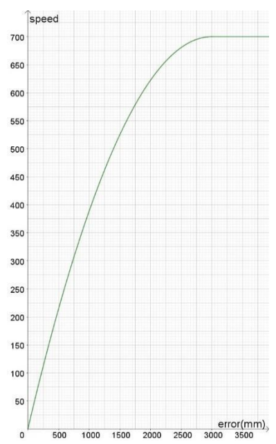
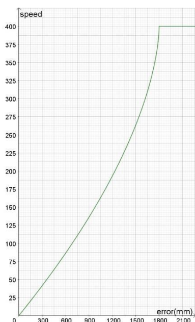
- p is a value that determines the slope of the diagram. If it is greater than 1, the convex diagram would be produced. The more value of p would generate more convex diagram. If the value is between 0 and 1, the convey diagram would be produced. The more close the value to 0 will generate the more convey diagram. We use it to determine whether it is important to reach the destination carefully or reach it quickly (see figure 3 and 4).
- d can be achieved by following equation:
$$d = MEr / \sqrt[p]{MSp} \tag{3}$$
Therefore, we have three parameters that needed to be set: MSp, MEr and p. The effect of changing these parameters is shown in figure 3 and 4.
3.2 Path Finding
As described in previous TDP, we use RRT [4] as a path-finding algorithm. This year we made some improvements in our implementation that one of them will be described below.
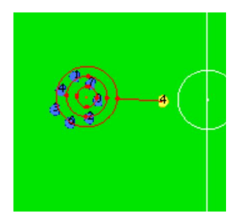
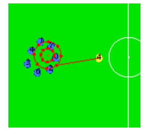
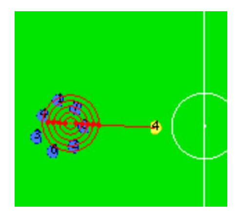
Finding a path to inaccessible destination. If a robot wants to go to a destination and that destination is surrounded with balks that cannot be crossed, the RRT algorithm can't find any path to that destination, because the algorithm is based on generating random positions and if that position is in a surrounded area, there is a balk between that position and any node of a tree that has been made with algorithm. So we cannot reach within the surrounded area and as the result go to the destination. We need to find a position outside that surrounded area, the nearest to the robot's position. To do this, we need to consider a circle with the destination as the center and the robot's radius (or any other value) as the radius. Then we need to get the points on the circle, which have the same angular distance to each other. After that, we must check if we can find the path to the nearest of them, if we could, then the process is done, if not, it is obvious that the circle is in surrounded area, so we need to increase the radius of circle and try the above process again.
We should set two parameters, one is "Radius increase rate", the value that will be added each time to the circle's radius, the other is "Angular distance between points", the angular distance between points on the circle. Reducing both "radius increase rate" and "angular distance between points" will increase accuracy of finding the nearest position. Figure 5 to 7 show the effect of changing these parameters on the selected point as destination. The blue robots are balks, the yellow robot is one that want to go to the destination, the red dot in the center of circles is the primary destination and the red dots on circles are candidates to be the final destination.
3.3 Decision Layer
As described in the previous TDP, Some functions in AI code are specified to help the robot to do its best depends on which situation is provided by the position of the robot, other teammates and opponents. Also, it is important where the ball is and which robot controls it. By these functions, the robot decides which duties how can be done in this situation.
This year, we improved these functions, Moreover for improvement of robot's decision, make it more intelligent according to robot's term (like position and ball owning) and game term (like stop or play). For each step, every robot (just in our team) should take place as a defender or attacker.
The robot should learn in the environment and take action depends on what it had learned. We defined states, which show the modes of game, and actions, which show the operation that robot can take, related to the current state. To perform it, we weighted actions from one state to another state (weighting actions means assign a number to actions), so robot decides which action is appropriate in each state depends on how big its weight is. Therefore, it is important to weight actions carefully. A human should do this part and then agent (robot) uses it as defined. After each game, the sum of weights of all selected actions should be maximum. So in this way, agent learns from the environment, saves the previous result and at taking action, surveys the results.
The transition rule is by equation 4 [5].
$$Q(state, action) = R(state, action) + Gamma * Max[Q(next state, all actions)] \tag{4}$$
Q is what explained above for saving result. This formula shows how saving result and then survey the result take place. R is which part that human enters it to weight actions. Gamma is a coefficient learning which is between 0 and 1. We choose it 0.9. As it is obvious in equation, first time that each action is selected in state, there is no result for it, so just action's weight is important.
So in brief, every step, robot recognizes the state then chooses next state (human predicts it before and gives it as code), then chooses the best action according to current state and next state.
State shows the environment and game in different modes. For example, the game is in play and the robot is in the third part of ground near our goal and has the ball (or not). Then next state is like the current state, so the most weighted action is pass then shoot and so on. Agent chooses to pass (because there is no result for this action or the previous results show that it is appropriate) and do it in the way explained in pass function.
For multi-robot system, every robot should choose an action in a way that is good for other teammates. In other words, each teammate robot chooses the best action for itself and helps its teammate to choose its best. In addition, the weight of actions for each robot depends on other robots situation and decision [6].
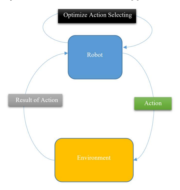
In figure 8, "optimize action selecting" refers to the learning process. In this process, robot learns if this action is good for this state according to Result of action. Then keep it in its memory to use it for forwarding decisions.
We should mention that we implement this algorithm for one robot completely, but it is not completed for all robots of the team in a collaborating environment. It will be completed soon. So we just mentioned about what it would be in the collaborative environment and did not explain it more.
References
- Omid Robotics Team. : OMID 2018 Team Description paper. Technical report, ECE Department, Shahed University of Tehran.
- http://www.usdigital.com/products/encoders/incremental/linear/E4P
- M. Khanloghi, O. Najafi, M.A. Ghasemieh, A.Mohammadi, A.M.Matin. Immortals 2019 Team Description Paper. RoboCup 2019 SSL, 2019.
- LaValle, Steven M: "Rapidly-exploring random trees: A new tool for path planning". Technical Report. Computer Science Department, Iowa State University.
- http://mnemstudio.org/path-finding-q-learning-tutorial.htm
- Reinforcement Learning: An Introduction Richard S. Sutton and Andrew G. Barto