OP-AmP 2019 Extended Team Discription Paper
Takamichi Yoshimoto, Takato Horii, Shoma Mizutani, Yasuyuki Iwauchi, Shota Zenji
Asagami Works, Osaka, Japan
https://www.youtube.com/user/AsagamiWorksOPAmP/
Abstract This paper introduces explanations of hardware, circuit, and software of a RoboCup small size league team "OP-AmP". The most characteristic point in our team is that our robots can kick a curve shoot by using a multi-angle kicking device and high-speed dribbling device. The skill enables the robots to perform more flexible in games than other teams.
In this year, we proposed a new dribbling device, which powerfully handling the ball to keep the success rate of the curve shoot. A stable position control system in the local control loop in the robot was introduced to tackle the same issue. For the strategy system (i.e., AI system), we employ an evaluation mechanism to assign optimum rolls for robots based on the game situation. Further, a camera filter was installed to compensate the differences between received positions.
Introduction
OP-AmP is a team of RoboCup SSL leagues established in 2011, and most of the members graduated from RoboCup team "KIKS". We won second place in RoboCup JapanOpen 2016, 2017 and 2018. Further, we participated in RoboCup 2017 Nagoya Japan and developed by a robot equipped with our unique mechanism of a kicking device.
This paper explains a system of our robot and software. We extended our robot to fourth generation based on 2017 models. The robot has a kick device with a variable angle mechanism, which realized a curve shots. They diversify strategies during the game. We will improve the dribble device to stabilize the curve shot toward RoboCup 2019. These devices are described in detail in section 2. In the following section 3, we describe circuit boards of our robot. The feature of the circuit is that current vector control is applied to motor control. This control system improves responsiveness and controllability in a low-level controller (i.e., motor control). Also, a stable position control system in the local control loop in the robot was introduced. On the software side, we explain an evaluation mechanism to assign optimum rolls for robots based on the game situation. Further, we explain a position compensation and a trajectory generation. In addition, we describe a method to apply velocity-bounding proxy-based sliding mode controller (VBPSMC) as a high-level controller and an optimization scheme of its control parameters. These systems are described in section 4.
Hardware
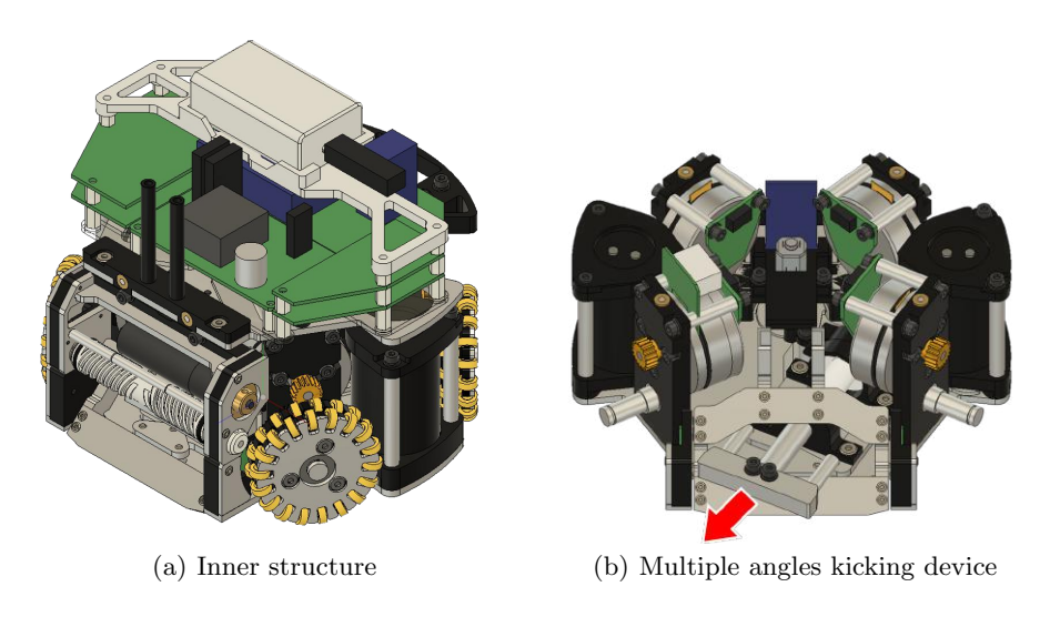
We developed a new robot in RoboCup 2017[1]. The CAD image of the robot is shown in Fig. 1. Table 1 shows basic specifications of the robot. It is a feature of robot that it is equipped with a multiple angles kicking device using a geneva drive mechanism. The robot can shots in one of five directions regardless of the direction of the robot. The robot can curve shot with that the kicking mechanism and the dribbling device. This robot is developing for the purpose of diversifying the strategy in the SSL game. The main progress of this year is feedback on the problem of the 2017 model. We will describe detailed information, problems of the 2017 model and improvement methods.
Basic specifications
| Model | 2017 - 2019 |
|---|---|
| Weight (without battery) | 2.20 kg |
| Main materials | Aluminum alloy(A2017), POM |
| Driving motor | maxon EC45 flat 30W (gear ratio 3.6:1) |
| Wheels | Double layered omni-wheels (small wheels 18 pcs x 2) |
| Small wheel material | urethane rubber (diameter=8mm, width=3mm) |
| Kicking device | Multiple angles kicking device with geneva drive x1 |
| Chip kicking device x1 | |
| Dribbling motor | maxon EC 16 30W (gear ratio 2.1:1) |
| Dribbling roller material | silicone sealant |
Maintainability
Considering maintainability of the robot, almost of the fastening is unified to the cap bolt (M3 x 8 with spring washer). As a result, it can be disassembled with a single screwdriver, and there is no need to worry about the type of bolt at the time of assembly.
Omni-wheels
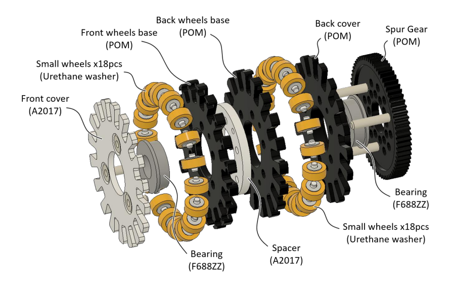
We use double layered omni-wheels to ensure smooth running and grip. Small wheels(18 pcs x 2) are stacked alternately to reduce the thickness. Considering impact resistance, the outer edge is made of aluminum alloy(A2017). For weight saving, POM is used for internal structure. By using two bearings and extending the fitting length, it is configured to be able to hold it stably even in a cantilever.
Curve shots
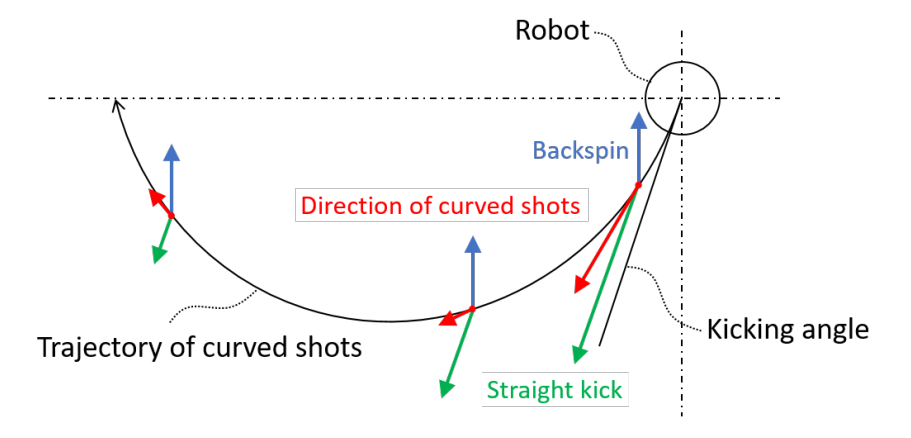
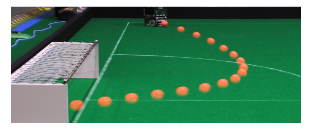
We noticed the possibility of curve shots while using the robot with multiple angles kicking device. As shown in the Fig. 3, by kicking in the diagonal direction while adding high-speed backspin, the ball draws a curve trajectory with the attenuation of the kick power. The curve shoot is very effective against AI which assumes only a linear shots, and it can provide advanced tactics closer to human soccer. For example, in the case of a free kick near the goal, conventionally the goal keeper should have been wary of only pass shoots because the direct shoot course is blocked by the defenders. However, if the shoot curves, the keeper must also consider the danger of direct shoot. This is exactly like a scene of human soccer.
Curve shoot has great merit, but some problems also arise. The most serious problem is that the stability varies with the field. If the field is different, the friction condition changes. The kicking power has sufficient margin and can be adjusted according to the field. However, since the backspin by the dribbling device uses the revolution number close to the limit of the motor (about 15000 to 20000 rpm of the roller), the adjustment range is small. Also, in an environment with a lot of friction, if the high-load rotation continues, the motor may generate heat and the characteristics may deteriorate.
Concept of new dribbling device
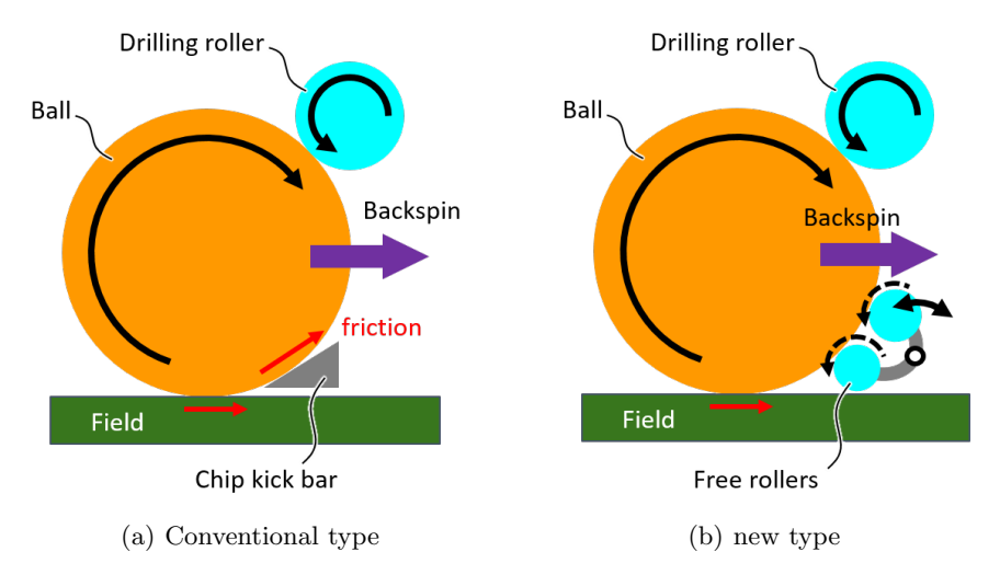
In order to stabilize the curve shoot, a dribble device that can stably apply high speed backspin with less load is needed. Therefore, we devised a concept to remove a tip kick and add a new dribble roller. Fig. 5 shows the concept image.
A chip kick has been required as a means for avoiding a opponent robots in the front. But our robots can also avoid opponent robots using the multiple angles kick device. Also, if the bound converged after the chip kick, the goal was accepted in the past, but now it is no goal. Therefore, removing the chip kick, we are considering installing more stable dribbling device.
The idea of a new dribble device shown in Fig. 5(b) places the rollers above and below. As usual, the upper roller gives backspin to a ball. The lower roller is free and is held rotatably. It closely contacts passively when the ball is drawn and supports to stably hold the balls attracted to the robot.
Conventionally, as the ball that was drawn in was touching the chip kicking bar, friction increased and it became a load shown in Fig. 5(a). Also, the relative positional relationship between the robot (roller and chip kicking bar) and the ball fluctuated depending on the field, which was one cause of instability.
We believe that these problems can be solved with the new concept, we are developing a prototype for RoboCup 2019.
Circuit
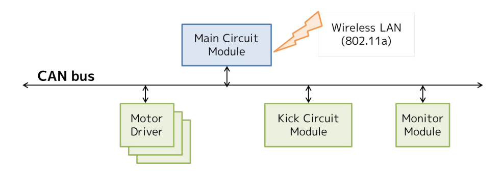
The hardware of the robot circuit uses the almost same thing as the 2017 model. Each circuit is independent as a module, and each circuit is mutually connected by CAN bus. The circuit configuration is shown in the Fig. 6, and the main specifications of each circuit are shown in the table 2. This circuit configuration makes it easy to design each circuit as a module, and it is possible to reduce the time and labor required to deal with the case where the hardware is changed. It is also easy to add devices with arbitrary functions after the robot is completed. Each module connected to the bus is not limited as long as it supports CAN.
In this circuit, mbed is used for the main circuit module and dsPIC is used for the other module. Data sent from AI in UDP format is received by the main circuit. The main circuit decodes the necessary data and transmits the command to other modules such as the motor driver module and the kick circuit module. In addition, each module sends its own state to the CAN bus. For example, the kick circuit module transmits the state of the ball sensor and the power management module transmits the state of the battery. Information on each module required by AI is transmitted from the main circuit by wireless LAN. The motor is controlled by current vector control. This makes it possible to handle a 3-phase motor like a DC motor, and the responsiveness of the motor can be improved. For details on this, please refer to textbooks and 2017 TDP.
Specifications of circuit
| Description | |
|---|---|
| MCU | mbed LPC 1768(main), dsPIC33EP64MC504(others) |
| Wireless Transceiver | Wireless LAN (IEEE802.11a) |
| Battery | Lithium polymer battery(14.4V 1800mAh) |
| Ball Sensor | IR photo IC (S6809) |
Position control
Many teams including us are performing position control of the robot on the AI computer side. However, due to the influence of many delays such as SSLvision and wireless, it is difficult to improve the performance by using the position control of the AI computer. In order to solve this problem, it is effective to perform position control on the robot side. It is expected that various delays can be reduced and the control cycle can be made faster. In this paper, we show the comparison of the performance between the case of performing position control on the AI side and the case of performing the position control on the robot side by using simulation.
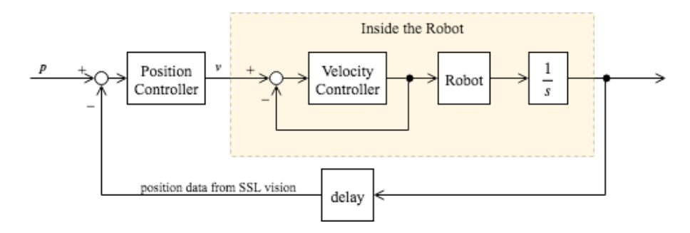
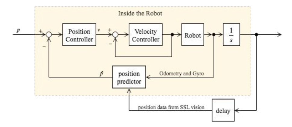
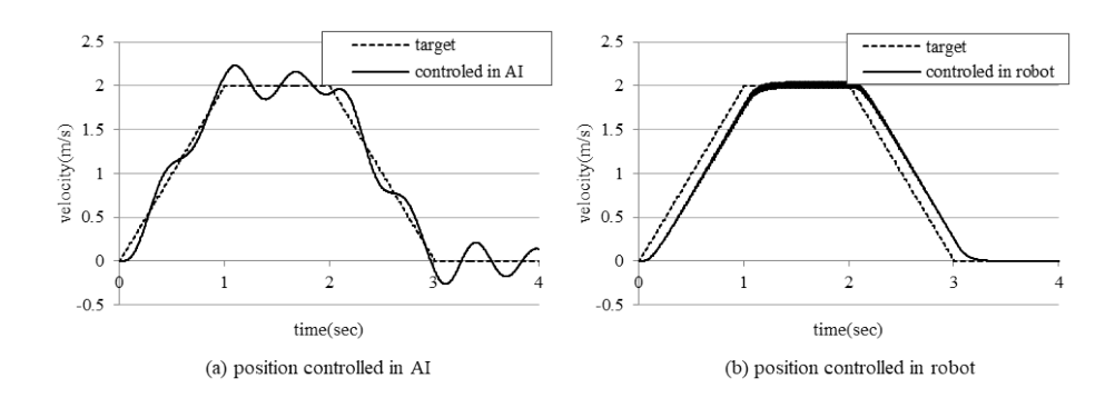
The Fig. 7 and Fig. 8 shows the control model used for the simulation. Fig. 7 shows the control model for position control on the AI side. The position control cycle of AI is 60 Hz, which is rate-limited by SSLVision. At this time, it is assumed that the delay due to SSLvision and AI is 0.1 sec (6 frames). Speed control is performed inside the robot, and its control cycle is 240 Hz. Fig. 8 shows the control model when position control is performed by the robot. The robot estimates its own position using an encoder attached to the tire and a gyro sensor. Since the position control is performed inside the robot, it is performed at 240 Hz which is the control cycle of the robot itself, and it is not affected by the observation of SSLvison. Also, AI sends the position of the current robot to the robot simultaneously with the position command. The robot internally performs sensor fusion of the current position from SSLvision and the self position estimated. This can reduce the cumulative error of the estimated position.
The Fig. 9 shows the results of the two controllers when the target position is given. At this time, the position controller generates the target trajectory based on the trapezoidal acceleration profile.Fig. 9(a) shows the robot velocity when position control is performed on the AI side, but the speed is not stabilized due to the influence of the time delay. In addition, overshoot and vibration also occur around the target position. Fig. 9(b) shows the results when position control is performed inside the robot. The speed of the robot follows the trapezoidal acceleration profile, there is no vibration near the target position, and the convergence time is faster.
From these simulation results, it is shown that performing position control using sensor fusion inside the robot has good results in improving the stability and responsiveness of position control.
Software
Overview
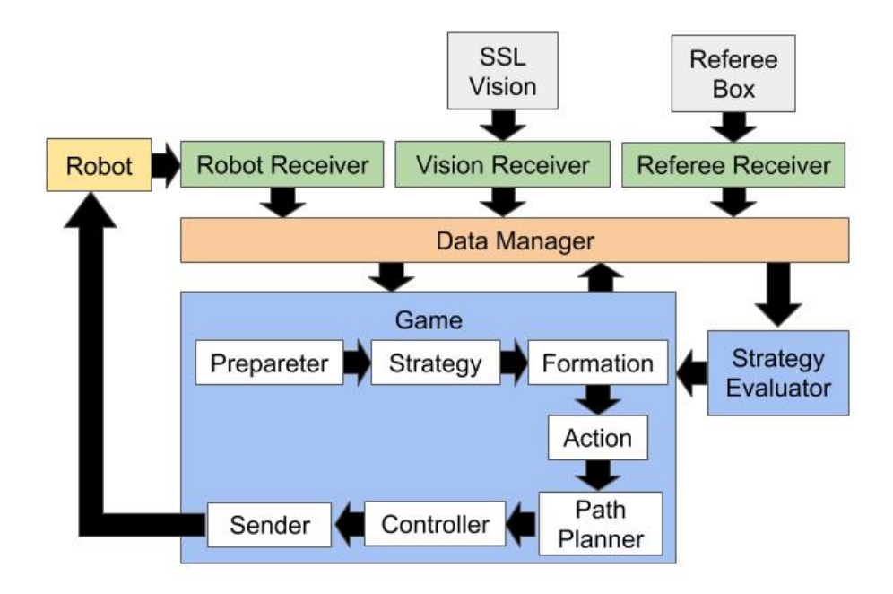
Fig. 10 shows a overview of our AI system. The system has three receiver modules, and each of them receives data from SSL-Vision server, Referee Box, and our robots, respectively. Received data is stored in Data Manager for use by other modules. Game module has several submodules. Each of these submodules analyzes the situation of the game, decides the strategy, generates the route, etc. Strategy Evaluator module performs evaluation and analysis necessary for strategy decision within the Game Module.
Strategy evaluate module
Strategy Evaluator calculates Striker Score, Defense Score, Pass Score for each player robots. Strategy Evaluator is executed in a calculation cycle independent of Game module. The calculation time of Strategy Evaluator increases according to the number of effective players. If Strategy Evaluator is executed within the Game module, the calculation of the control system will be affected, so the Strategy Evaluator is an independent module.
Striker Score is indicating whether the player robot is suitable for approaching the ball. The Player with the highest Striker Score in them is in charge of Striker, for example, executing a shoot. Striker Score at the time t (SSt) is calculated by Equation (1). ss^t is an evaluation value calculated from the current ball and Player state, for example, it increases as the distance to the ball is short. SS_{t-1} the previous score. r is a value indicating how much to consider the previous evaluation score and is a value from 0 to 1. I is 1 if SS_{t-1} is the maximum among all the players, and 0 otherwise. From this r and I, prevent an excessive change of Player in charge of the Striker.
$$SS_t = ss_t \times r + SS_{t-1} \times (1-r) \times I$$
Defense Score is a value indicating whether the Player is suitable for defending the opponent shoot or pass. In the calculation of Defense Score, at first, calculate evaluation value for each point within a certain range around the position of Player. The point with the highest evaluation value is defined as P^d, and the evaluation value is Defense Score. This point P^d can be commanded to the Player as it is as the defensive position, and it is used within the Game module. P^d can be commanded to the Player's defensive position, and it is used within the Game module.
Pass Score is a value indicating whether the robot is suitable for receiving a pass. In the calculation of Pass Score, it is similar to Defense Score, calculates the evaluation value for each point within a certain range around the position of Player. The point with the highest evaluation value is defined as P^p, and the evaluation value is Pass Score.
Position compensation
The number of camera boundaries has been increased due to the field enlargement in the division A field. When a ball is captured by multiple cameras or when the trajectory of the ball crosses some boundaries between cameras, the distortion of the ball trajectory should affect the estimation of the ball velocity. To tackle this issue, we introduce the compensation module of the ball positions between captured ones and the real one. The compensation module employed the coordination transformation considering the consistency of the camera boundaries. In particular, we use the following homography transformation formula
$$p = HP$$
Let p = [x, y, 1]^t and P = [X, Y, 1]^t are the ball coordinates in the real environment (i.e., soccer field) and the captured ball coordinates by cameras, respectively. Also, let H is the homography transformation matrix.
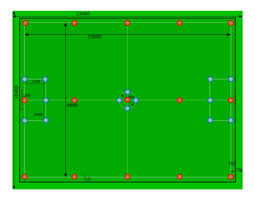
In Fig. 11, the red circles show the positions, which were utilized to estimate the parameters of the homography transformation matrix H. The blue circles indicate the ball positions for evaluation of the matrix H. We estimated the homography transition matrix H according to the coordinates of the red circles and validated the error (i.e., distance) between real ball coordination and captured ball coordination with or without the homography transformation. Table 3 indicates the error according to the blue circles in Fig. 11 under both conditions. It can be seen that the homography transformation enables to reduce the error of ball coordination between the real one and the captured one.
Coordination error between the real ball positions and the captured ball positions
| With homography transformation | Without homography transformation | |
|---|---|---|
| 89.4mm | 483.5mm |
Trajectory generation based on the spline curve
The rules on contact between robots during games were raided up from last year's competitions due to the introduction of the auto referee system in the SSL games. The auto referee system strictly judges, therefore it is necessary to generate a smooth trajectory to avoid other robots. Our system uses the RRT method for generating route of robots. In the RRT, the generated nodes were individual, and the target points were connected with discretely. The robot behavior might become discontinuous due to the above features. To realize smooth and flexible behaviors of robots, it is necessary to smoothly connect the generated target points.
To deal with this problem, we employed the spline curve function to connect with discrete targets. The spline curve function generates the coordinations between two discrete points P^s (i.e., the start position of the spline curve) and P^g (i.e., the goal position) according to the control interval of the AI system, δt. Let T is the moving time from P^s to P^g, and V^s and V^g are the velocities at the position P^s and the potion P^g, respectively. The spline curve function is described as
$$3(P_g - P_s) - 2(V_s - V_g)t^2 + V_s t + P_s$$
Here, the velocity V^g is decided according to the target speed of the robot.
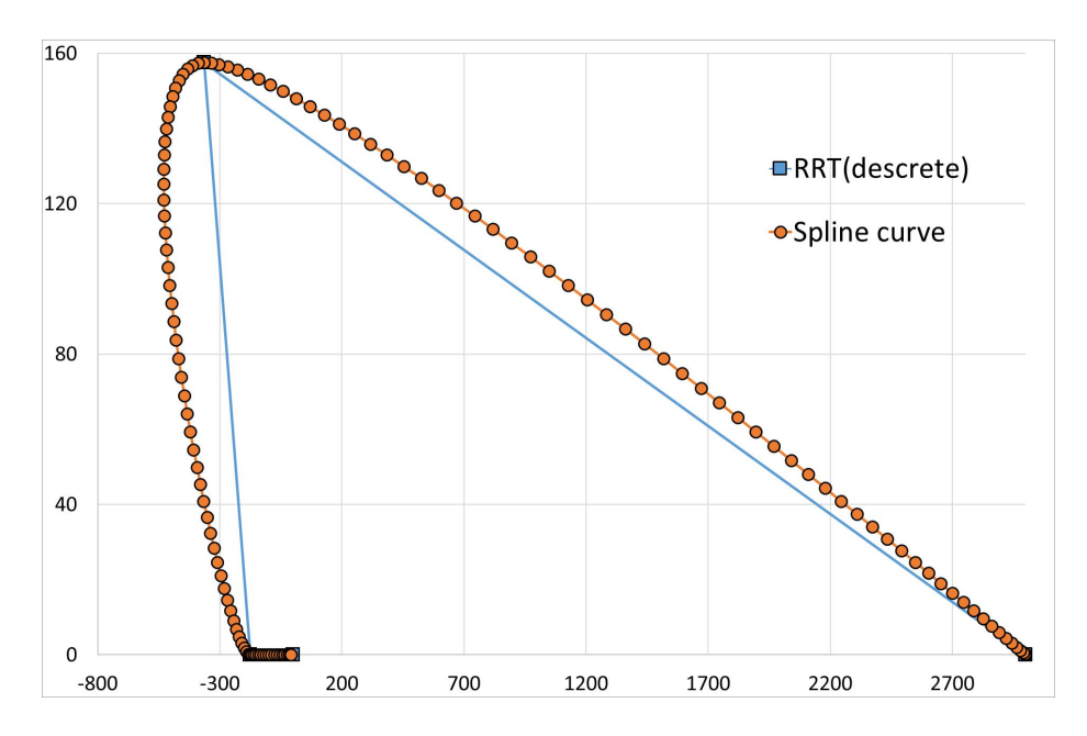
Fig. 12 shows the discrete target positions generated by the RRT algorithm and the spline curve according to the target positions. From this figure, it can be seen that a continuous trajectory can be generated by using the spline curve, and the trajectory enables the robot to move smooth.
High-level controller
The PID controller has been used on the SSL robots because the controller is stable and responsive. However, during SSL games, target positions and velocity of the robots are suddenly changed by the strategy system owing to execution of a ball tracking behavior and an obstacle avoidance behavior. The threshold value of a target speed is also limited in some game situations (e.g., "stop"). The PID controller might become unstable and unresponsive in the above situations.
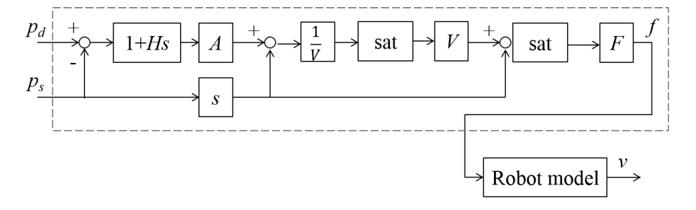
In order to deal with these problems, we utilize a velocity-bounding proxy-based sliding mode controller (hereafter VBPSMC) [2] as a high level controller. The VBPSMC is an extension of the PID controller and includes a velocity limit to modulate controller outputs. Fig. 13 shows a block-diagram of the VBPSMC with a robot model. The VBPSMC outputs force based on a difference between a target position and a robots position, and the robot model converts the force to velocity for actual robots as a controller signal.
Parameter optimization based on the Bayesian optimization for the high-level controllers Adjusting parameters of a controller according to field characteristics (e.g., a coefficient of friction) is important to control robots stably. However, it is not realistic to search the parameters exhaustively because we do not have much time for the adjusting.
To reduce the time for the exploration of optimal parameters for our control system, we employ a Bayesian optimization (hereafter BO) scheme [3, 4]. The BO utilizes a Gaussian process [5] , which is one of probabilistic processes, to represent a relationship between parameters and evaluation values. The Gaussian process is able to suggest next search points of a parameter space by using an acquisition function. We use elapsed time as the evaluation value while a robot reaches target points, and the BO optimize parameters on the VBPSMC.
Communication data
Our AI system sends control commands to robots and receives the robots status during games. Both sender and receiver utilize the UDP protocol to communicate our robots. The AI system sends commands in 1/60 second intervals, and all robots send their own status in two second intervals. Table 4 shows a control command set for our robots from the AI system. Table 5 indicates the data structure of the robots status. The control command includes an angle of a diagonal kick, which is one of characteristics of our robot. The AI system uses the robots status to select strategies and assign specific roles to the robots (e.g. the strategy evaluate module).
Packet of control command for robots
| Data | Size |
|---|---|
| Control speed | 2 byte |
| Move direction | 2 byte |
| Angular speed | 1 byte |
| Direction of rotation | 1 bit |
| Dribble speed | 2 bit |
| Kick flag | 1 bit |
| Kick type | 1 bit |
| Kick speed | 3 bit |
| Direction of diagonal kick | 1 byte |
Packet of robot's status
| Data | Size |
|---|---|
| Ball sensor signal | 1 byte |
| Battery voltage | 1 byte |
| Charger voltage | 1 byte |
| Circuit existing flag | 1 byte |
References
- Takamichi Yoshimoto, Takato Horii, Shoma Mizutani, Yasuyuki Iwauchi, Yutaka Yamada, Kousei Baba, and Shota Zenji: OP-AmP 2017 Team Description Paper, RoboCup 2017
- Kikuuwe, Ryo, Takahiro Yamamoto, and Hideo Fujimoto. "Velocity-bounding stiff position controller." Intelligent Robots and Systems, 2006 IEEE/RSJ International Conference on. IEEE, 2006.
- Calandra, Roberto, et al. "Bayesian gait optimization for bipedal locomotion." International Conference on Learning and Intelligent Optimization. Springer International Publishing, 2014.
- Snoek, Jasper, Hugo Larochelle, and Ryan P. Adams. "Practical bayesian optimization of machine learning algorithms." Advances in neural information processing systems. 2012.
- Rasmussen, Carl Edward. "Gaussian processes for machine learning." (2006).