RoboCIn 2019 Team Description Paper
Cecília Silva, Felipe Martins, João Gabriel Machado, Lucas Cavalcanti, Renato Sousa, Roberto Fernandes, Victor Araújo, Vinícius Silva, Edna Barros, Hansenclever F. Bassani, Paulo S. G. de Mattos Neto, Tsang Ing Ren
Centro de Informática, Universidade Federal de Pernambuco. Av. Prof. Moraes Rego, 1235 - Cidade Universitária, Recife - Pernambuco, Brazil.
Abstract RoboCIn has been participating in Latin American Robotics Competition (LARC) since 2016. In this paper, we present the first version of our robot intending to compete in the Small Size League (SSL) in RoboCup 2019 in Sydney, Australia. The main focus of this paper is to detail the mechanical and electronic systems we developed, as well as the strategy and software solutions we designed to attend the RoboCup competition.
Introduction
RoboCIn is a team from Universidade Federal de Pernambuco (UFPE), Brazil. In 2016 we started to participate in the IEEE Very Small Size Soccer (VSSS) at LARC, and since 2018 we are developing the first version of our robotic system to compete in Small Size League (SSL). Last year we participated for the first time in the SSL in LARC at João Pessoa, Brazil and achieved fifth place.
This paper presents an overview of our system. Section 2 describes the mechanical design which was inspired by the work of other established teams in the competition. Section 3 explains the proposed embedded design, composed by the electronic project and proposed communication protocol. Section 4 shows our software and strategy development. Section 5 summarizes our work and present future works.
Mechanical Design
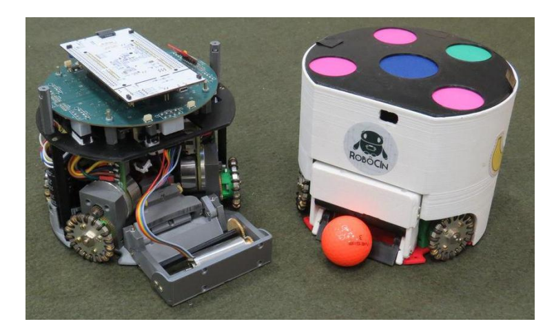
In Figure 1 we present an internal and an external view of the second version of our robot. We use Autodesk Inventor to design the robot's parts, and we printed 3D pieces for all the structure to reduce costs and decrease the number of machined parts. It's a challenge to have a reliable robot while we use 3D parts. Some challenges we faced during development in 3D were the differences in size between the projected parts and those printed due to thermal expansion and associated uncertainties. Also, the same part on two different printers has different dimensions. Our robot specifications can be found in Table 1.
Robot Specifications
| Specification | Value |
|---|---|
| Robot Version | 2019 |
| Driving motors | Maxon EC-45 flat - 50W |
| Max % ball coverage | 19.55% |
| Microcontroller | STM32F767ZI |
| Gear Transmission | 18 : 60 |
| Gear Type | External Spur Wheel GTF Robots SW-504 |
| Total Weight | 2.44 kg |
| Dribbling motor | Maxon EC-max 22, 25W |
| Encoder | MILE 1024 CPT |
| Dribbling Gear | 50 : 30 |
| Dribbling bar diameter | 15mm |
| Max. kick speed | 6.5m/s |
| Communication Link | nRF24L01+ |
| Battery | LiPo 2200mah 4S 35C |
Motion System
Extensive research was made to define the ideal place to position the motors, considering cost, dimensions, reliability, and efficiency. The Maxon EC-45 flat 50W [7] was chosen because it meets the requirements of speed and torque for our robot. We use four motors to drive our robot, the two front motors are spaced angularly to form an angle of 120° centered with the robot, and the two rear motors are placed symmetrically concerning the longitudinal axis. This arrangement was chosen to provide more space to the dribbler and kicker mechanisms and giving more torque in forwarding and backward movements.
The omnidirectional movement is provided by four omniwheels SW-504 from GTF Robots [3] with 50mm diameter and 18 aluminum rollers. Both the motion system and dribbler mechanism use spur gears to optimize the internal space and in the driven wheels also provides the necessary torque to drive the robot. The gear ratio used for the motion system is 3:10, and for the dribbler mechanism is 50:26.
Dribbler
We use a Maxon EC-22 max motor to drive the dribbler mechanism together with two spur gears. The dribbler bar has 14mm diameter and a study is being developed to choose the best material among the following: silicone sealant, rubber, solid silicone and flexible filament. In addition, a ball centering prototype is also being developed based on the model presented by Op-AmP team in 2017 [12]. This mechanism has two helicoids at the extremes of the bar so that when in contact with the ball produces an effort that pushes the ball to the center of the dribbler bar.
The positioning of the dribbler on the robot chassis was based on a trigonometric study according to the 80/20 rule [10] which defines that 80% of the ball needs to be free. Therefore we were able to calculate that the ideal height of the dribbler is 43.8 mm, and this height was the starting point to project the dribbler subsystem.
Kicker
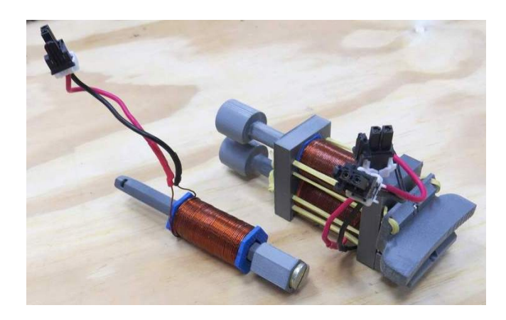
The kicker mechanism has a hexagonal shape to prevent the model from rotating during movement based on Immortals' team [4]. This format also allows accommodating an M8 x 65 bolt that will propel the mechanism when the coil is triggered. The rest of the moving piece was made in 3D printer, for both the chip kick and the front kick, as shown in Figure 2. For the coil we used enameled copper wire AWG 22 with six turns to ensure correct coil operation. To return the kicker to the starting position a common rubber alloy was used.
Embedded Design
Our electronic system has two boards: the main board and the kicker board and was based on Tigers Mannheim's 2018 Open Source Release [11]. The main board is responsible for all the embedded computing and motors controllers, while the kicker board is responsible for raising the battery supply and activating the kick. A more detailed description of the main board and kicker board are given in Sections 3.1 and 3.2, respectively.
Main Board
The main board has an STM32F767ZI processor from STMicroelectronics with an ARM Cortex M7 core, 320kB RAM, a max clock of 216MHz, 6 SPI interfaces, all pins are preemptive and up to 18 timers are available. This processor is responsible for tasks such as wireless communication, to control the kicker board and the dribbler, the reading of sensors and to control the driven motors.
We use a nRF24L01+ transceiver to communicate the base station and each robot. It works with a 2.4GHz frequency and maximum transmission rate of 2Mb/s. This module shows good performance in competitions, because of it high baud rate and low power consumption. The communication between the transceiver and the processor is established through the SPI interface.
The activation of the four Maxon EC-45 flat 50W motors and the Maxon EC-max22 25W motor is done by one Allegro A3930 motor controller and six IRF8113 MOSFETs circuits for each motor. We use one of the eighteen timers to generate PWM signals to control the motors speed. The driven motors are equipped with a built-in encoder with resolution 1024 pulses per revolution. We also have LEDs to display critical information about the robot, and a buzzer with the purpose of increasing the security while handling of the robot.
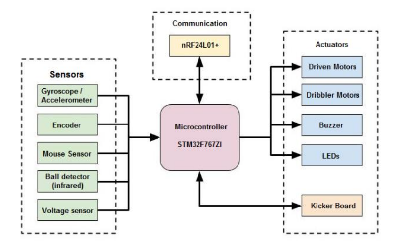
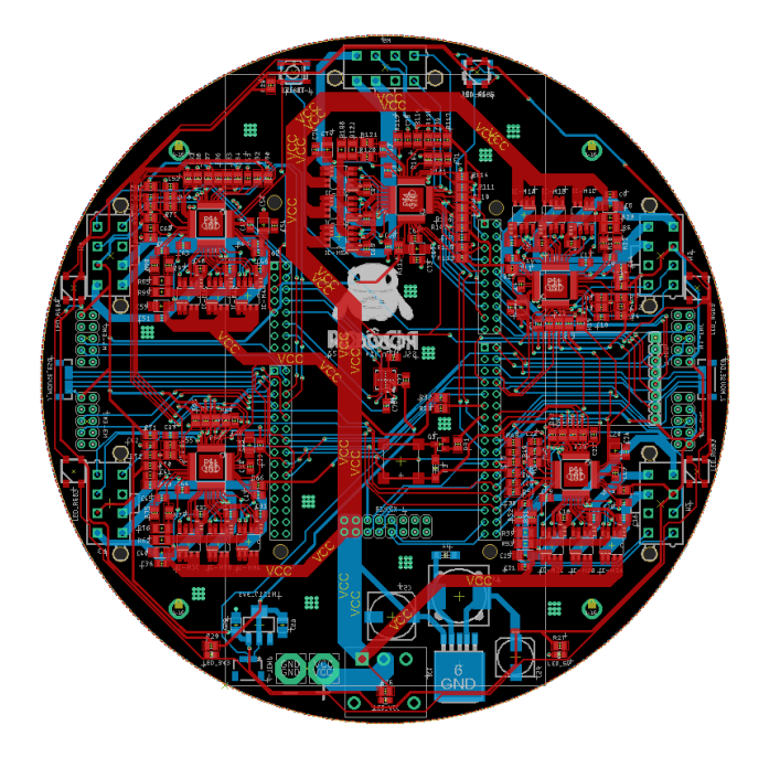
Additional information to improve the reliability of the motion control can be acquired by the MPU6000 module, with an accelerometer and a gyroscope, and two lasers sensors (ADNS9800). These sensors also communicate with the processor through the SPI interface. The main board has communication with infrared sensors to detect the ball presence, a battery level checker and capacitor voltage meter from the kicker board. The main board includes a voltage regulator to 5V with LM2596 converter and a voltage converter to 3.3V with LM1117. The architecture block diagram is shown in Figure 3. It contains the Arm M7 processor and the previously described components. Figure 4 shows the main board design. It contains the four motor drivers with the required MOSFETs for their operation as well as one motor driver for the Dribbler motor, two voltage regulators (5v and 3.3V) supplying devices such as the nRF module, LEDs and encoder, a reset button, an on-off switch and connection with the kicker board.
Kicker Board
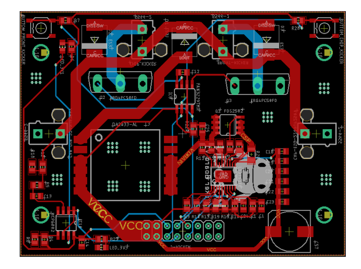
The Kicker board has a DC-DC converter with boost topology. It is responsible for raising the voltage from 14.8V (4S LiPo battery) to 250V then it charges two parallel capacitors of 3300µF. When the kicker board receives the kick signal, the capacitors discharge into a solenoid which activates either the chip kick or the straight kick, according to the processor signal. Figure 5 shows the Kicker board design.
An Analog to Digital (ADC) converter ADC1225051 is used to measure the voltage in the kicker capacitors which is sent to the main board through SPI protocol to control charging and discharging when required. This signal goes through a voltage divider and an Operational Amplifier (Op-Amp) in comparison mode which turns off a LED when the capacitor is discharged to indicate that the robot is safe for handling by the team members. Also, a safety button on the board allows the manual discharge of the capacitors without the need for a signal from the main board.
Communication protocol
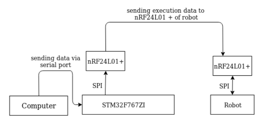
We use an nRF24L01+ module [8] to broadcast to all six robots in the same channel. We use the star topology in this project to send individual messages to each robot more effectively through one base station. This module also can send messages in a rate up to 2 MBps in six different pipes. Thus, our protocol was build based on the nRF24L01P library, where we created a class called nRF24Communication, and we set some parameters, such as the data rate (2MBps), the transmitter operation (single channel for all robots) and the way in which packets are sent.
Bitfield data structure was chosen to build the packets as it allows bit manipulation. Therefore, we can generate packets only with the needed bits, reducing the total number of bytes and allowing sending a faster message. We choose to send the data in an union data structure so that the packet can be decoded as a vector of bytes.
Table 3 shows the packet fields and its structure. The first field defines the message type that allows creating new message types to the protocol. The second field has the identification of the robot that should read the message. The next four fields are the linear velocity (v^x and v^y), the angular speed (ω) and the robot orientation concerning the origin (θ). The remaining fields refer to the kicker mechanism. Figure 6 shows the communication flow.
Protocol message fields
| TypeMsg | ID | Vx | Vy | W | θ | Kick | Chip | Force |
|---|---|---|---|---|---|---|---|---|
| 4 bits | 4 bits | 20 bits | 20 bits | 20 bits | 20 bits | 1 bit | 1 bit | 1 bit |
| 12 bytes |
Strategy
As the team is participating for the first time in SSL, the early software studies were dedicated for defining the architecture and strategy to path planning. Subsection 4.1 presents the software architecture proposed by the team and the data flow in this architecture and Subsection 4.2 detail the path planning algorithm chosen by the team.
High level architecture and data flow
We used two architectures as a basis for the construction of the proposed structure. The first is Skill, Tactics and Play [1], which suggest the use of three levels of tasks. The higher level task is Play, which defines the plays in which all robots are playing. In a Play, every player executes a Tactic in a state machine where each state is a Skill. A Skill is a set of low-level functions such as pass the ball, kick in the goal or move to a set location. The second architecture was proposed by the ER-Force team [5]. In this architecture, each player acts as an autonomous agent to the lower level tasks but with a central software that determines the high-level functions for all players. As the players are agents, they can communicate with each other to combine moves and make decisions faster. However, the full use of this architecture increases the number of message exchange between players and can lead to a bottleneck in the communication network.
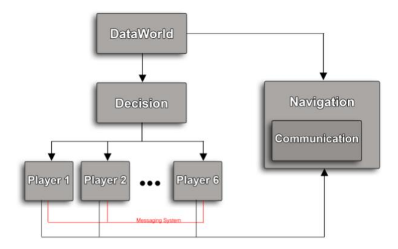
With the use of concepts of both architectures, RoboCIn team proposes to use a hybrid architecture based on a master control. It may evolve into a decentralized approach, with players acting as autonomous agents. Figure 7 shows an overview of this architecture showing the used classes. Another advantage of our architecture is the parallelism, where each class can become a thread. In the next subsections, we detailed each class present in the architecture.
DataWorld. This class is responsible for receiving external data from SSL-Vision [13] and SSL Referee. Due to the high rate of receipt of external packages (up to 800 Hz), we decided to create a thread only for this function. Also, we established that this class would be responsible for handling any possible receipt of player data. This feedback from the players can enhance their position with the use of filters, such as the Kalman or Markov filter.
The Frame structure is the output to subsequent classes. This structure has the updated positions and contains the most recent information on the positions of the elements in the field: robots, ball, and the commands received by SSL Referee. In this way, the other classes of the architecture can request the most current Frame when it is needed and do not cause a bottleneck while receiving the data.
Decision. This class stands for the choice of Play that will be executed by the players, and it runs in parallel along with the other threads with the frequency of 60 Hz. It requires the most recent Frame in DataWorld with each execution. The choice of Play to be executed can be influenced by the game situation and the by the referee signals. There are static situations such as the corner kick, kick off and penalty kick where a predefined play can be chosen.
There is a situation in the game where it requires a more refined choice of play like when the ball is free, and the game is being played. In this situation, the tactic of the defenders and goalkeeper must be chosen so that they can block an eventual opponent's kick. The tactics of the support and attacker players are selected so that the players can position themselves to pass and receive the ball in conditions to kick to the goal, respectively — the general situation of the game also influence the tactics of advanced players.
Player. This class defines each tactic previously chosen. It receives as input the position of all elements in the field and the move defined by the Decision class together with the tactic each player will execute. Thus, the Player class set the state machines of each tactic, and they can be executed independently. Also, there is a framework for exchanging messages from threads via the software to allow cooperation between players.
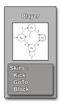
The internal architecture of the Player class with state machines of the tactics and definitions of the Skills, as shown in Figure 8. The Skill class defines path planning algorithms, opponent marking algorithms, kicking decision and others. Because one thread controls each player, it is expected as the output of each thread only one goal position of each player.
Navigation. This class receives the most recent position of the player coming from DataWorld and the target positions from each Player as inputs. Then, it chose the navigation strategy to calculate the linear and angular velocities for each robot. The navigation task also runs in parallel with the code with an update frequency of 60Hz, to ensure a high correction rate at speed sent to the robot.
The Communication class is defined inside the Navigation class and is responsible for sending information from the base station to every robot in the field. Communication was chosen to be defined inside Navigation instead of one in each Player to avoid concurrency of many threads trying to access the same resource. Therefore the radio is only used by Navigation thread when it has the new speeds for each robot.
Path Planning
Path Planning is is one of the most critical Skills in this architecture. It is responsible for moving the robot around the field and is the first to be implemented. The first step is to plan the path to be performed out in such a way that this path is optimal and it avoids the collision of the robot with obstacles. To plan the path, it must have a navigable map representation of the world. There are several approaches, like potential fields, Voronoi diagram, and visibility graph [9].
We first considered the use of potential fields method since we already use this approach in VSSS. To represent the SSL division B field [10] with 9m × 6m with an accuracy of 1cm it would be necessary to use 8MB memory to map for each robot. It would generate a significant overhead of time to go through all this map with this accuracy.
Another possibility of map representation is the use of the Voronoi diagram [2], which employs those paths that maximize the distance to the obstacles as possible paths. This approach aims to find the safer path, but such a path may become too long and too slow to use in a competition. The computational cost of the construction of a Voronoi diagram is O(n × log(n)). However, since it is necessary to execute the fastest path to the goal, the Voronoi diagram was not used.
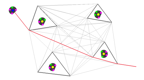
Visibility Graph [6] presents lower computational cost than potential fields and can find the smallest path to the target position among the analyzed approaches. It constructs a representation in graphs where the obstacles are polygons, and the initial and final points are vertices of the graph. As the robots are circular, they were represented as equilateral triangles circumscribed to the circle that represents the robot. Thus, the edges of the polygons representing the obstacles are considered as edges of the graph.
From the representation of the obstacles and the initial and objective points, the visibility graph is constructed connecting all the vertices of the graph, except those that cross an obstacle. Thus, possible paths that pass close to obstacles will be created, but they will not collide with any object and are smaller than those proposed by the Voronoi diagram. The computational cost of this approach is O(n^3), where n is the number of vertices in the graph, that is, the cost is proportional to the number of obstacles and the chosen representation for the obstacles. Figure 9 shows an example of the use of the visibility graph in SSL.
Conclusion
In this paper, we presented our first project to compete on SSL. To finish this project, we dived our efforts in 3 main areas: Mechanics, Electronics and Software Development. Because of this division, we could keep the team working simultaneously and start competing in such a short development time.
As this is our first project, we observe a few improvements we could do, such as the development of more reliable motion system, a better control strategy, a more efficient electronic board design and better decision software to choose roles for the robots.
Acknowledgement
This is work is supported by Centro de Informática (CIn) - UFPE, Laboratório para Integração de Circuitos e Sistemas (LINCS) and Centro de Tecnologias Estratégicas do Nordeste (CETENE).
References
- Browning, B., Bruce, J., Bowling, M., Veloso, M.: Stp: Skills, tactics, and plays for multi-robot control in adversarial environments. Proceedings of the Institution of Mechanical Engineers, Part I: Journal of Systems and Control Engineering 219(1), 33–52 (2005)
- Choset, H., Walker, S., Eiamsa-Ard, K., Burdick, J.: Sensor-based exploration: Incremental construction of the hierarchical generalized voronoi graph. The International Journal of Robotics Research 19(2), 126–148 (2000)
- GTF Robots: Omni directional Wheel SW-504 (6 2017)
- Immortals Team: 3D Printed Robot (2018), https://github.com/Ma-Ghasemieh/Immortals_ssl_opensource_mech
- Lobmeier, C., Burk, D., Wendler, A., Eskofier, B.M.: Er-force 2018 extended team description paper (2018), robocup Small Size League, Montreal, Canada, 2018
- Lozano-Pérez, T., Wesley, M.A.: An algorithm for planning collision-free paths among polyhedral obstacles. Communications of the ACM 22(10), 560–570 (1979)
- Maxon Motors: Maxon EC 45 flat datasheet (5 2017)
- Semiconductor, N.: nrf24l01+ single chip 2.4 ghz transceiver. Datasheet, September (2008)
- Siegwart, R., Nourbakhsh, I.R., Scaramuzza, D.: Introduction to autonomous mobile robots. MIT press (2011)
- Small Size League Technical Committee: Laws of the RoboCup Small Size League 2019 (12 2018)
- Tigers Mannheim Team: Open Source Software and Hardware (2018), https://tigers-mannheim.de/index.php?id=65
- Yoshimoto, T., Horii, T., Mizutani, S., Iwauchi, Y., Yamada, Y., Baba, K., Zenji, S.: Op-amp 2017 team description paper (2017), robocup Small Size League, Nagoya, Japan, 2017
- Zickler, S., Laue, T., Birbach, O., Wongphati, M., Veloso, M.: Ssl-vision: The shared vision system for the robocup small size league. In: Robot Soccer World Cup. pp. 425–436. Springer (2009)