RoboFEI 2019 Team Description Paper
Guilherme P. de Oliveira, Vinícíus M. Alves, Danilo Pilotto, Wesley de S. Motta, Leonardo da S. Costa, Guilherme Luis Pauli, Marcos A. P. Laureano, Carlos Alberto F. Cadamuro, Reinaldo A. C. Bianchi, Plínio Thomaz Aquino Junior, Flavio Tonidandel
Robotics and Artificial Intelligence Laboratory Centro Universitário da FEI, São Bernardo do Campo, Brazil
Abstract This paper presents the current state of the RoboFEI Small Size League team as it stands for RoboCup International Small Size League competition 2019, in Sydney, Australia, as well as works that are still under development. The paper contains descriptions of the mechanical, electrical and software modules, designed to enable the robots to achieve playing soccer capabilities in the dynamic environment of the Small Size League.
1 Introduction
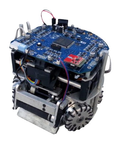
For the RoboCup 2019, the RoboFEI team intends to use the same electronics and mechanical design that have been used over the last years, as shown in Figure 1. Some significant advances were made in our software and firmware, which was verified in the XVII Latin American Robotics Competition (LARC). We have also been able to assemble the first prototype of our new mechanical structure. Our aim now is to improve the recently built software system and the mechanical design. With our researches, we hope to bring innovations and new ideas for the community.
2 Electronics
Since RoboCup 2014, RoboFEI's team released the current electronic design as open source to the community. All the schematics, layouts and firmware are available on-line, under a Creative Commons license, in RoboFEI's web-site (www.fei.edu.br/robofei). Currently, the electronic hardware remains the same update of last year, the components description are shown in table 1.
Table 1. Current Electronic Description.
| Device | Description |
|---|---|
| Main Board | CPU: Xilinx Spartan 3 FPGA operated with 50 MHz clock |
| MOSFET Driver | TC4427 working with IRF7389 MOSFET |
| Current Sensor | ACS712 with A/D converter AD7928 |
| Kick Board | Boost converter topology. |
| Kick Storage | Two capacitors of 2700 $\mu$ F, in parallel, charging up to 160V in 16s. |
| Kick MOSFET | IRFSL427, Id 72A DC. |
| Driving Motor | Maxon,EC-flat-45 50W with hall sensor. |
| Dribbling Motor | Maxon EC-max-22 25W with hall sensor. |
| Ball Sensor | TEFT4300 infra-red emission diode and photo diode pair. |
| Communication | nRF24L01 transceiver, 2 Mbps, 2.4/2.5 GHz. |
| Power Supply | LiPo, 3-cells (11.1V) and 2250 mAh capacity. |
2.1 Updated Wheel Control System
We currently use a distributed control system, where, some decisions and controlling actions are made in the high-level AI software, such as determining which velocity the robot should move to reach a desired point in the field, and another part of the control is done in the embedded firmware. To improve the performance of the robot it was studied and delimited what each part should do and how.
We fixed that all robots should receive its movement information in its own referential as $V_x$, $V_y$ and $\dot{\omega}$, which are its velocities on X, Y axes and the angular velocity on its own axis respectively. The referential used was that the Y axis is perpendicular to the front of the robot and the X axis is to the right of the robot.
In order to do this, all of the kinematics were remodeled and programmed into the firmware, this can be seen in Equation 1.
$$\begin{bmatrix} v_1 \ v_2 \ v_3 \ v_4 \end{bmatrix} = \begin{bmatrix} -\sin(\phi) & -\cos(\phi) & 1 \ \sin(\phi) & -\cos(\phi) & 1 \ \sin(\phi) & \cos(\phi) & 1 \ -\sin(\phi) & \cos(\phi) & 1 \end{bmatrix} * \begin{bmatrix} V_x \ V_y \ \dot{\omega} \end{bmatrix}$$
Where v^i is the velocity for each of the four wheels and φ is the angle of each wheel, which in our case is 33° for the old structure and 32° for the new one.
We also parameterized all velocity values on firmware and high-level software to work on the range from −100 to +100, where each 10 units represents approximately 0.2m/s for the X and Y axis.
To obtain the transfer function of the motor we've used its data sheet. The transfer function used by the team is shown in Equation 2 and was implemented using MATLAB and Simulink.
$$\frac{\dot{\theta}(s)}{V(s)} = \frac{33.5 * 10^3}{77.355 * 10^{-4} * s^2 + 13.203 * s + 1122.25}$$
Where ˙θ(s) is the angular velocity of the motor, V (s) is the voltage applied and s is the Laplace complex variable.
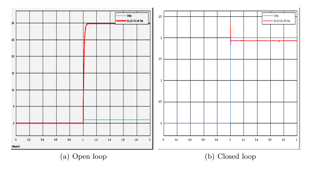
The step response in open loop of the system is shown in Figure 2(a) and in closed loop in Figure 2(b). Where the red curve is the system output and the blue one is the step input.
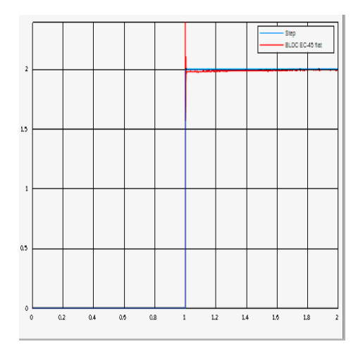
Utilizing the recommendations for sintonizing controllers it is possible to have zero steady-state error and decrease the overshoot in closed loop [2]. The system output in closed loop with a PI controller can be seen in Figure 3.Where the red curve is the system output and the blue one is the step input.
3 Mechanics
We've developed a new mechanical structure last year, however, it still needs some adjustments before testing in an actual game.
One of the disadvantages of the old structure is that it was made in its majority of steel parts, which made the robot quite heavy and expensive. The new structure is mostly made of 3D printing, which makes our robots lighter, faster and cheaper than the old ones. The new structure can be seen in Figure 4. Currently we aim to participate in division A and be a competitive team in it, to achieve this, most of our effort are in reducing the cost to produce more robots whilst maintaining its quality, in order to reach eleven robots.
Other disadvantage which led us to change our structure was the high maintenance time, mainly in the championships, where the time to do it is short. For example, to remove the new wheel set it is not necessary to disassemble the whole structure as it did before, now it is only fixed by two screws on the lower plate.
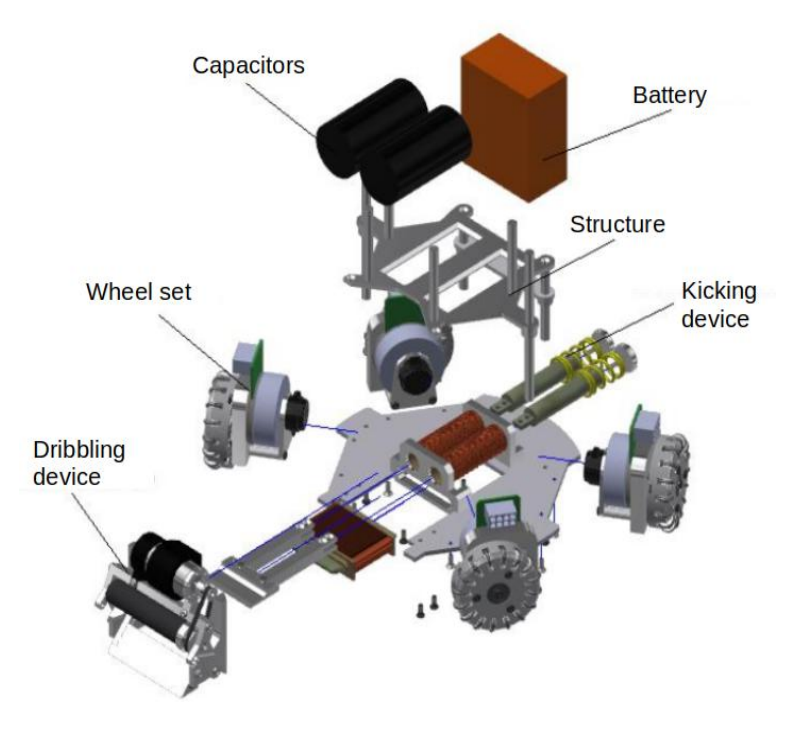
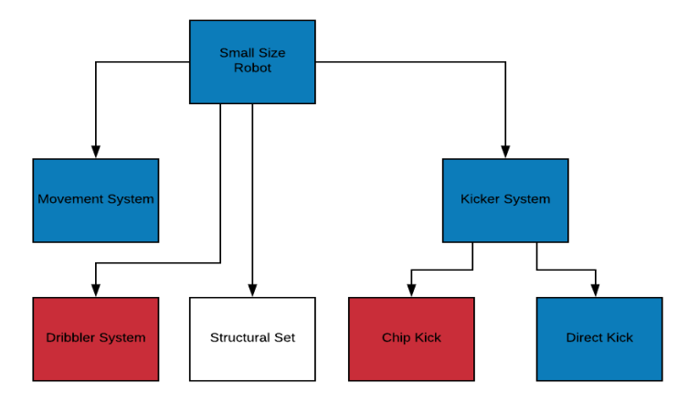
Table 2. Function and failures of the direct kick system.
| Project: | RoboFEI Small Size |
|---|---|
| Sector: | Mechanic |
| System: | Direct Kick |
| Set: | Direct Kick |
| Author: | Vinícíus Medeiros Alves |
| Function | Functional Failures |
| Not kicking the ball | |
| Kick the ball in a straight line while maintaining contact with the ground. | |
| Not kick in a straight line | |
| Make the ball bounce |
Moving on with the FMEA, it was needed to list the causes and effects of the failures, it is important to note that here will only appear causes related to the mechanical aspect of the robot. In order to list the causes all team members were consulted, the result can be seen on Table 3.
Table 3. Effects and causes of the direct kick system.
| Functional Failures | Effects | Causes |
|---|---|---|
| Not kicking the ball | Unable to score a goal or pass. | Broken rubber band; Solenoid piston stuck; Ball Sensor misaligned; Piston axis unscrewed; Unscrewed kicker; Solenoid short circuited to the structure. |
| Kick with a speed higher than 6.5 m/s | Violates the rules of the game. | Over dimensioned solenoid; Unregulated capacitor discharge time. |
| Not kick in a straight line | Makes it harder to execute some skills. | Gap between the kicker and its axis; Unscrewed kicker. |
| Make the ball bounce | Unable to score a goal or pass; | Kicker hitting outside the center of the ball; Ball stuck underneath the roller. |
Now it is need to evaluate the Risk Priority Number (RPN) which is the product of the severity (S), occurrence (O) and detection (D) of a given failure.
The criterion used to classify severity was that if a failure resulted in the robot not executing a primary function it would be given a value of 9 and if the failure resulted in a violation of the rules of the game it would be given a value of 10. For serious failures it would range from 6 to 8, and below 6 would be the failures that the team can still play a match without major consequences.
Since the occurrence is the rate that a given failures occurs, this was a little harder to evaluate, the values for each failure were defined based on the experience from past competitions, laboratory tests and the documentation of previous maintenances of the robots.
The detection is related to the method used to identify each failure, in our project it ranged from 5 to 1.
The S, O, D and RPN values for the direct kick system can be seen on Table 4. The failures with the highest RPN should be treated as fast as possible, since they represent a severe negative effect on the performance of the robot.
Table 4. Control, Severity, Occurrence, Detection, RPN and Recommended actions of the direct kick system.
| Functional Failures | Control/Detection | S | O | D | RPN | Recommended Actions |
|---|---|---|---|---|---|---|
| Not kicking the ball | Functionality tests. | 9 | 7 | 2 | 126 | Project revision; Preventive and corrective maintenance (The priority is to lower the occurrence) |
| Kick with a speed higher than 6.5 m/s | Adjustments using the Auto Referee | 10 | 5 | 2 | 100 | Project revision (Avoid both of the failure modes). |
| Not kick in a straight line | Assembly revision and visual inspection | 7 | 7 | 2 | 98 | Project revision; Corrective maintenance. |
| Make the ball bounce | Visual inspection | 7 | 5 | 2 | 70 | Project revision (Avoid the failure modes). |
This way, given the RPN for each failure of the system it is possible to determine which part of the robot should receive a more detailed maintenance or a special attention when projecting its mechanical components. These steps were applied on all of the systems of our robot and based on that it was decided which sets needed a complete rework.
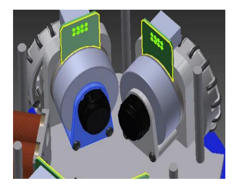
Using the RCM method described here, one of the systems that needed a rework was the encoder support. To avoid their misalignment a new support was created, it can be seen in Figure 6, they are now fixed by two rods in the lower part of the motor support, this way we avoid shocks caused by other robots to interfere with the encoders, also, with this geometry we were able to standardize the encoder support, this facilitates the machining of them. The support must be made of aluminum because the encoder plate holes comes from the manufacturer with 2.5mm metric threads and after a few tests with 3D printing we found that trying to print threads smaller than 3mm would not give us a good result, no matter how we did the configuration of the printer.
4 Software
As said in our latest TDP [4], we were developing a whole new software for the team. Now we are almost done implementing all the basic functions needed, a few of the new features will be shown here.
4.1 Software Structure
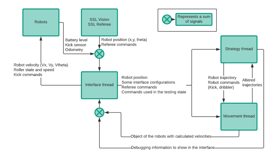
Given that handling all the interface events can use quite a lot of processing in some situations, therefore we've decided to have multiple threads handling certain parts of our software. In the current moment we have three threads in total, in which, the first is used to handle everything related do the interface, receiving data from the SSL Vision and SSL Refbox, sending and receiving data to the robots. The second thread is used to process the states of the game, Referee commands, calculate the positioning of the robots, decide which robot should be a defender or attacker, calculate the position of the goalie and trajectory of each robot using the path-planner. And the third thread is used only to maintain a real-time loop for the motion control of the robots.
We still aren't using a sophisticated controlling technique to control the position of our robots, but in a near future when it is implemented there will already be a functional environment to run the controller, currently this real-time loop runs in an interval of less than 15ms, and it is fixed that it will only return an information in the end of this period, this guarantees for us that approximately every 15ms our robots are receiving information correcting their velocities.
Since we are using QtCreator, all the communication between threads are done using the signal and slot mechanic, this way the information is sent simultaneously from the first thread to the second and third. Currently the threads work asynchronously, but the data shared between them is protected using a mutex. There are no priorities over which thread signal should be treated first, there is only a delay on the second thread of about five times the time consumed in one loop of the third thread, thus, the second thread generates a signal approximately every 75ms. This response time is still being adjusted, since it must be guaranteed that all processing is done within this period. In Figure 7 it is illustrated how this works.
4.2 User Interface
Some problems we've had with our past software versions were the lack of organization on the interface and absence of configurable characteristics of the robots and skills.
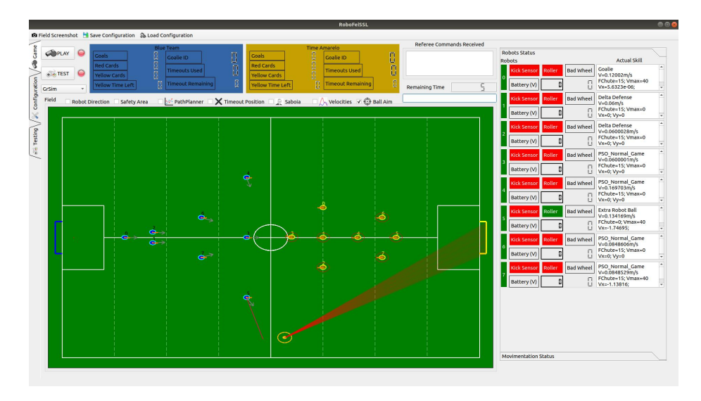
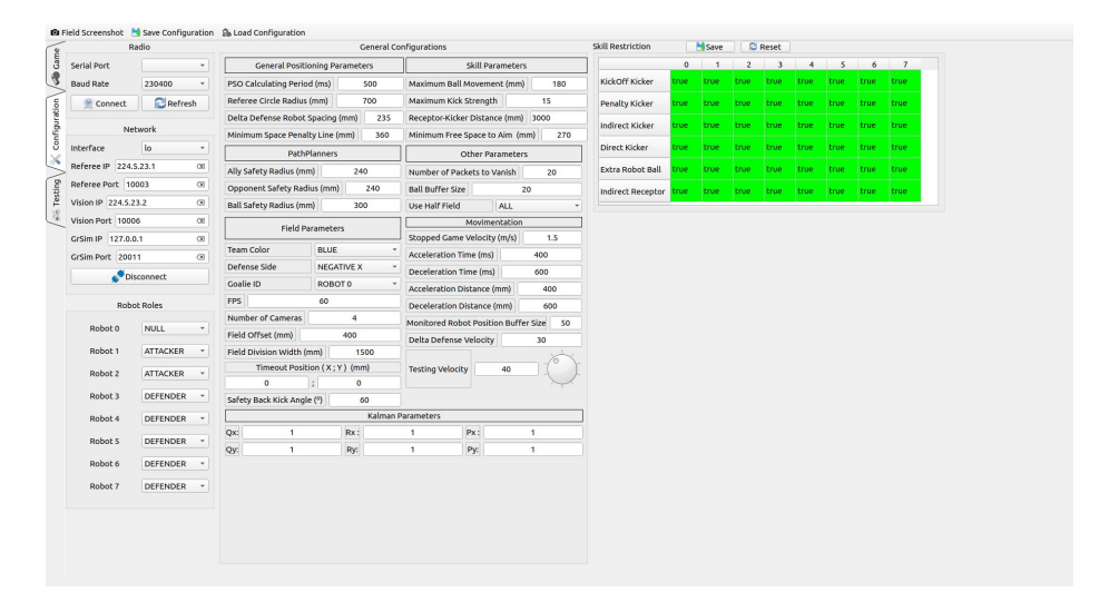
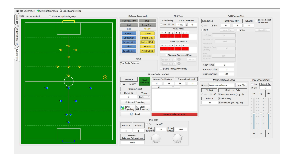
The new software has only three tabs. The first is the tab used in game game, it contains the image of the field, some information's about the robots, like battery level, kick sensor and current skill, this tab can be seen in the Figure 8. The second tab is used for configuration of all the parameters available, a few of them are, serial port of the radio, SSL Vision and SSL Referee connection parameters, some constants used in skills and many others, this tab can be seen in Figure 9. The third tab is completely dedicated to do various tests with our robots, this facilitates discovering bugs in the software and mechanical/electronic problems with the robots such as bad contact in some connections of the board, this tab can be seen in Figure 10.
4.3 New Positioning System
The PSO proposed by [5] is an optimization algorithm based on a population of particles that have obtained recognition in the solution of several problems, with simplicity and using few computational resources. The PSO algorithm objective finds an optimal solution in a search space, through the exchange of information between individuals of a population determining which trajectory each individual should take in the search space.
The velocity V and the position P of the particles is updated from the equations 4 e 5 respectively:
$$V_{ir}(t+1) = \omega V_{ir}(t) + c_1 r_1(pbest(ir,t) - P_{ir}(t)) + c_2 r_2(gbest(t) - P_{ir}(t))$$
$$P_{ir}(t+1) = P_{ir}(t) + V_{ir}(t+1)$$
Where V denotes velocity, ir is the robot r from particle i, ω is the inertia factor used to balance global and local exploration, r^1 (cognitive part) r^2 (social part) are randomly distributed in the range [0, 1], and c^1 (confidence parameter for the cognitive part) and c^2 (confidence parameter for the social part) are constant parameters called acceleration coefficients.
According to [6], a soccer match is divided into two attitudinal concepts: defense and attack. Being that defense of a team must a) cancel the finishing situations, b) recover the ball, c) prevent the opponent from progressing, d) protect the goal and e) reduce the opponent's playing space; and in the attack: a) maintain possession of the ball, b) build offensive actions, c) progress through the opponent playing field, d) create situations of finalization and e) finalize in the opponent's goal. These attitudinal concepts and other tactical principles will be prioritized in the development of objective functions applied to the defense positioning.
To test the possibility of applying the PSO algorithm, in Latin American Robotics Competition (LARC) 2018 some mathematical functions were implemented to calculate defensive positions according to the following rules:
– The minimum distance of the robots in relation to the opponent to make it difficult to move and the possibility of receiving or making passes or kick to goal; – If the view of the robots in relation to a certain point (in this case, the goal) is blocked; – If all opposing robots have at least one allied robot blocking the view of the goal, prioritizing the opposing robot with possession of the ball.
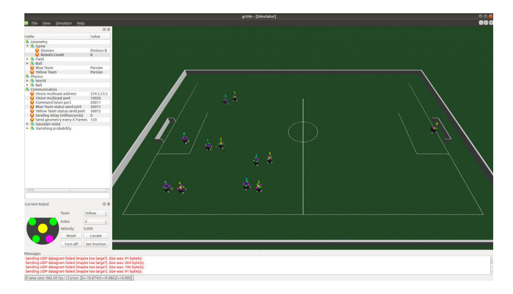
Initially, the grSim simulator [7] was used to validate the proposal in a real game situation as seen on Figure 11.
Acknowledgements
We would like to thank, in advance, the Small Size League Committee, for the consideration of our material. We would like also to immensely thank the staff of Centro Universitário FEI, for all the help we always received from them.
References
- Mathew MacDougall, Gareth Ellis, Amy Hashemi, Emma Jackson, Oon Chu Lip, Nicolas Ivanov, James Petrie, Khashina Tonks-Turcotte, Chantal Sousa, Kenji Lai, Bowen Xu, Qiqi Li, Eric Goto, Dana Deutsch, Anthony Buonassisi, and Marcus Lee. 2018 team description paper: Ubc thunderbots. ., 2018.
- Karl Johan Åström and Tore Hägglund. PID controllers: theory, design, and tuning, volume 2. Instrument society of America Research Triangle Park, NC, 1995.
- John Moubray. Reliability-centred Maintenance (RCM). Lutterworth, Inglaterra Industrial, 2000.
- Guilherme P. de Oliveira, Vinícíus M Alves, Danilo Pilotto, Lucas A. da Silva, Julia B. Drapella, Danilo R. Vassoler, Igor do N. Alves, Raphael B. Bezerra, Fernando T. H. Darsono, et al. Robofei 2018 team description paper. ., 2018.
- J. Kennedy and R. Eberhart. Particle swarm optimization. In Neural Networks, 1995. Proceedings., IEEE International Conference on, volume 4, pages 1942–1948 vol.4, Nov 1995.
- Israel Teoldo da Costa, Julio Manuel Garganta da Silva, Pablo Juan Greco, and Isabel Mesquita. Principios taticos do jogo de futebol: conceitos e aplicacao. Motriz. Revista de Educação Física, 15(3):657–668, julho 2009.
- Valiallah Monajjemi, Ali Koochakzadeh, and Saeed Shiry Ghidary. grSim RoboCup Small Size Robot Soccer Simulator, pages 450–460. Springer Berlin Heidelberg, Berlin, Heidelberg, 2012.