RoboIME: From the top of Latin America to RoboCup 2019
Carla S. Cosenza, Gabriel Borges da C., Gabriel Fernandez, Gustavo C. K. Couto, Leonardo G. Gonalves, Hugo Gomes, Lucas Germano, Lucas G. Corrêa, Luciano de S. Barreira, Luis D. P. de Farias, Luis R. L. Rodrigues, João G. O. C. de Melo, Matheus Bozza, Matheus P. de Souza, Nicolas S. M. M. de Oliveira, Onias C. B. Silveira, Rebeca P. dos Reis, Renan P. de Souza, Sergio G. S. Dias, Yugo Nihari, Paulo F. F. Rosa
Instituto Militar de Engenharia, Rio de Janeiro, Brasil
Abstract This paper describes the electronic, mechanical and software designs developed by the RoboIME Team in order to join the RoboCup 2019. The overall concepts are in agreement with the rules of Small Size League 2019. This is the sixth time RoboIME participates in the RoboCup.
1 Introduction
RoboIME is a Small-Size team from the Instituto Militar de Engenharia, IME, located in Rio de Janeiro, Brazil. This is the eleventh time the team participates in a competition, being the best result first place in the Latin American Robotics' Competition 2017, four second places in RoboCup Brazil Open 2011, Latin American Robotics Competition 2012, RoboCup 2018 division B and Latin American Robotics Competition 2018.
All students that work in the SSL project are members of the Laboratory of Robotics and Computational Intelligence at IME. Team's previous works were used as reference [2] [3] [4] [1], as well as the help from former members of the team as consultants and tutors.
This article describes the team's general information and improvement in the most recent semester, since our previous TDP for RoboCup 2018 has detailed explanations on our previous changes. This article is organized as follows: software in section 2, embedded eletronics in section 3 and mechanical design in section 4. Conclusions and future works are discussed in section 5.
2 Software Project
This paper reports the main improvements and changes since 2018 RoboCup project.
2.1 Statistical Module
A module called the Statistical Operational Software (SOS) is being developed in the AI. The main function is to process parallel information and give feedback to the AI with information that could help during or after the game. For example, it could detect that one robot is slower than the other and inform this information in order to have someone verify if there is a problem with that robot. This kind of data is not processed on the main AI and might help with certain in-game decisions. The objective, in a long term, is to transform this module into a selflearning AI. A few features have been developed and integrated into our AI, such as:
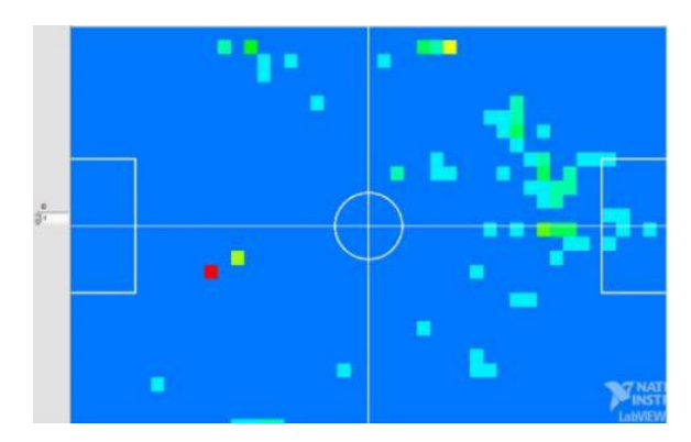
Heat map The heat map is inspired by those seen in soccer games. The field is divided into a grid and each cell is approximately the robots size. A histogram of where each robot is located in the field is calculated in every iteration, generating a matrix. This matrix must be normalized in order to find the probability. Currently the heat map is just a visual tool, but in the future it will be very useful for self-learning methods. The results look like this (see figure 1):
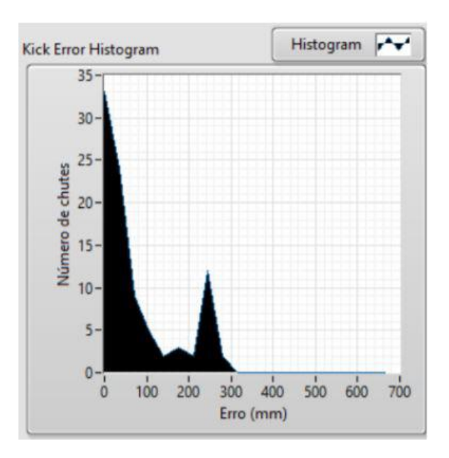
Kick error histogram This histogram calculates the distance between the point where the ball entered the goal and the point, on the goal line, that the attacker was aiming for. A test routine was projected to make the attacker kick as many times as desired and the result is plotted in a graph. One test is shown below (see figure 2) (y-axis: Number of kicks and x-axis: error(mm)): This test provides a method of analyzing the difference of precision between two versions of a attacking robot.
Pass analysis This test was originally made to verify the force of the robots kick when passing the ball to some other robot, but it can also be useful to learn when the in game pass is working, of RoboIME's team or the enemys team. Basically, it searches for a kick and for the robot of the same team that receives the ball and controls it for a certain time.
2.2 Passing State
In order to implement the second striker, some changes were made to the original passing state. Now when the second striker personality is active, the attacker has more than one option for passing. The decision of which robot to pass to take in consideration the following three factors:
- The time it takes an enemy robot to intercept the line that unites the attacker and the striker
- The distance between the receptor and the goal
- The biggest opening angle from the receptor to the goal
All these factors are normalized in a 0 to 1 value, and statistical weights are attributed to all of them. The receptor with the highest normalized sum of the weighted factors is the chosen receptor.
2.3 Receiving the pass
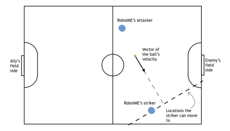
In order to increase the amount of correct passes, an analysis of what is the best algorithm of receiving a pass was made. After selecting the position of the striker using the Inverse Best-Y, it is necessary to have it wait for the ball and re-position itself if necessary. Two approaches were analyzed for when the striker is waiting for the ball: allowing it to move only parallel to the x-axis and allowing it to move only perpendicularly to the vector that represents the velocity of the ball. This restriction in movement only happens during the pass state, guaranteeing that the striker will not present this behavior in other conditions. Using the new statistical module with the pass analysis feature, it was possible to analyze which algorithm presented the biggest quantity of successful passes. The result was that the perpendicular approach was best, possibly due to the fact that the striker had a shorter distance to move (see [3]).
2.4 Personalities
For the advancement of the AI, some changes were made to the personalities (see Personalities in [4]) in order to have a better understanding on how the personalities work.
– Defender: The main change implemented in the defender was the ManMarker behavior, that was based on ER-Force's TDP (see in [5]). This behavior's goal is to mark enemies without ball possession but that could receive the ball through a pass, for example. The defender robot that exercises this function positions itself separately from the defence wall of robots, in front of the enemy robot chosen, but still close to the goal. Based on the distance to goal and on the distance to ally robot with ball possession, the algorithm calculates the most dangerous and the second most dangerous enemies. Hence, the ManMarker has the option to mark any of these enemies robots. It is important to highlight that the code allows to choose between two formations:
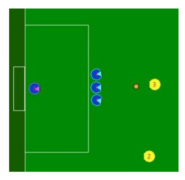
- All defenders in the wall of robots (see figure 3).
- Defense with one ManMarker (see figure 4).
The choice between formations 1 and 2 and the selection between two options of enemies to mark can be made manually through a button before the match or during breaks. It is considered for further improvements an integration with the SOS parallel system to decide which formation is more adequate. The former is thought to be more effective against teams with low passing rates, whereas the latter is thought to be good against teams with high passing rates. Now, when an enemy robot with ball possession approaches the wall of robots, one of the defenders also assumes the offensive behavior as described in the RoboCup TDP (see reference [2]). The chosen defender may throw the ball away or to block an enemys shot, depending on the situation.
- Goalie: The general behavior of the goalie was modified, working now as a state machine, where the actual state is determined by the distance between the enemy attacker and the ball. First, the closest enemy to the ball is defined as the enemy attacker. Then, the goalie will choose one of the following states based on the enemy attacker distance d (in mm) from the ball. Let dinf be the behaviour distance lower bound and dsup the upper bound.
- d > dsup: The trajectory line of the ball is determined by the balls current location and its velocity slope.
- d > dinf and d ≤ dsup: The trajectory line will be the one connecting the enemy attacker and the ball.
- d ≥ dinf : The trajectory line will be the line that passes through the ball and which slope is given by the orientation of the enemy attacker.
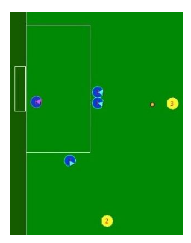
In each state, a trajectory line is calculated and the goalie behaviour determined. The goalie will intercept the line if it meets the goal and kick the ball out of the goal area. If the line does not meet the goal at any point the goalie will then go to one of the posts or the goal center, depending on the slope of the line that passes through the ball and center of the goal, waiting in a good position for a change in the ball trajectory.
Striker: The striker now assumes a man-marking behavior when an enemy robot has the ball possession, which is determined by whether the ball is closest to an ally or enemy. First, for each enemy robot it is calculated its distance from the ally's goal and from the robot which has control of the ball. The one which presents the smallest addition of these two results is considered the most dangerous enemy. Then, it is applied the GoTo method to position the striker properly between the enemy which has the ball and the most dangerous one. This position is set next to this last robot mentioned, along the vector that links these two enemies. The striker is oriented in order to kick the ball away from the man-marked robot, in case the most dangerous one receives a pass from the other.
Second Striker: The robots can now assume this new temporary offensive personality, which appear on the passing state and direct or indirect kick for the ally team. Outside these situations, the personality ceases to exist and gives its place to another defender. The main objective of the personality is for the Attacker to have more than one possibility for passing and, therefore, making it less predictable. In passing situations, the second striker gets ready to receive a pass, assuming a slightly retreated position, also chosen by the Inverse Best-Y method, different from the one assumed by the striker. This personality can only be active when all the robots are in the field and can be deactivated manually through a button before the match or during the breaks.
2.5 Path planning
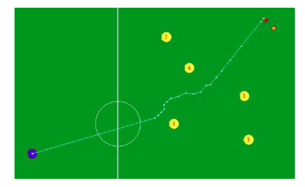
– Obstacle Avoidance: This year RoboIME changed its path planning algorithm. In order to achieve an optimized trajectory and to avoid problems that may occur with the Potential Field approach, an extended rapidly exploring random tree (ERRT)(see reference [6]) based algorithm was developed for critical roles, such as the attacker and the striker.
This new approach builds a tree from an initial point until it reaches the goal point. The trajectory generated, for example as depicted on Figure 6, is guaranteed to be free of obstacles: on the other hand, in some situations it may not be the optimal path, since it can have many extra points. For this implementation, the team was mainly inspired by an article about path planning, which describes with many details how both algorithms work.
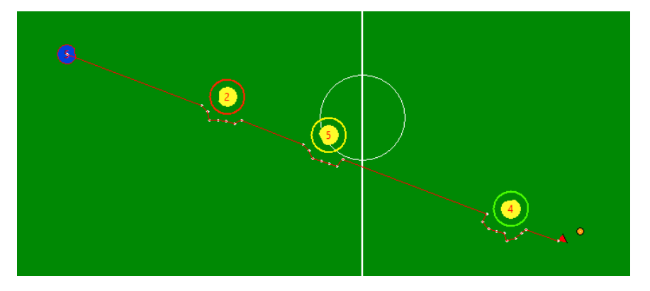
Moreover, since this algorithm demands a lot of calculation, another improvement could be done. Instead of applying the ERRT along the whole path between the robot and its goal, first it is checked if the simple straight line satisfies a free obstacles route. In the positive case, there is no need to calculate another path, while in the negative case it is either not necessary to apply the algorithm to the full extension, but only in the vicinity of obstacles along this line. This optimization is able to generate a valid path with less calculations, for example as shown in Figure 7.
3 Electronics Project
Since the RoboCup 2018, a lot of effort has been put into making the electronic project more robust. Standardizing the production of the boards proved to be an improvement in the boards reliability. Also, the modularization of the project proved, once again, to be useful, enabling removing a defective robot mid-game, debug it, and placing it back in action in a span of a few minutes. The modifications made in both the main board and in the kicker board also made the robot much more reliable. The LARC 2018 competition was very useful to test the changes in the project.
3.1 Firmware
The firmware remains mainly the same, with the addition of the acceleration and gyrometer values of the robot given by the IMU, which gives higher precision in the calculation of the robot's speed and orientation. Another addition was the id switching mechanism, having its value saved in the flash memory of the microcontroler.
Robot Communication One big improvement from RoboCup 2017's project to RoboCup 2018's is the addition of communication from the robots to the AI software. Previously, due to difficulties in the firmware configuration and hardware limitations, information from the robots could not be transmitted to the AI. For example, if the ball sensor is activated or not or even if it is working. With such limitation fixed, this forward-backward communication becomes possible, enabling more possibilities for the IA system.
3.2 Control
Maintaining the robot at the expected speed or position is very important so that the software project is able to work properly. To try to keep the robots moving as expected, there are several routines to check or filter the results obtained from the vision system and the robots themselves.
Dealing with a non-ideal movement In cooperation with the each wheel's speed being controlled, it is important to control the overall direction that the robot follows. Wheels accelerate differently from each other. One wheel achieving the final speed before the others can compromise the entire movement of the robot, changing its direction due to the robot's rotation. Incremental acceleration of the robot with the slower one acting as the leader is a possible solution to this problem, therefore acceleration should be sacrificed over overall trajectory precision.
3.3 Board Designs
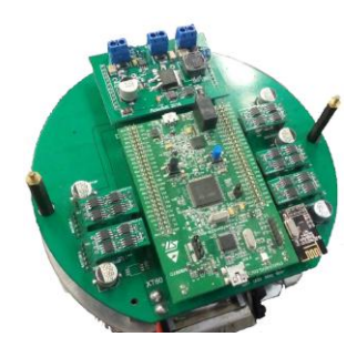
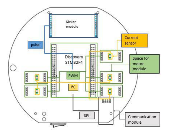
RoboIME's hardware platform kept its same structure, as seen in figure 8.
The motor module was changed to one single PWD13F60 IC that is the full H-bridge. Having a higher maximum current limit and the same pinout as the previous board, both can the used in the same robot.
Stamp module This module is responsible for performing all the logical functions, serving as a brain for the electronic system. The module is a commercially available board - the STM32F4-Discovery; it is a development kit that aggregates an Arm Cortex M4 microcontroller with a series of peripherals like a debugger, a motion sensor, two push buttons and two USB plugs.
Main Board The Main Board, figure 6, provides physical support to the other modules and connection between them and the robots actuators, sensors and battery. Most of the main board is composed of simple routes and planes making these connections. But it also implements some important circuits, such as the currents flowing to each motor and the battery voltage. Further adaptations were made aiming the for at RoboCup 2018. An important one was the thickening of the tracks, which was implemented after a power loss test. This allowed more current be available for the motors as the tracks resistance is decreased. Another one was the exchange of the current shunt monitors INA220 to INA169, once they are analog, which caused the data reading to become considerably faster. Also, a MPU-9250 was added in order to improve the control system by providing more stability to the robot. In addition, there was a migration from the use of an ID selector to the use of a 7 segment LED display with a button, to make the id switching more intuitive. More LEDs for debugging were added as well. A mini SD Card slot was also included and it communicates via the same SPI as the MPU-9250. The top 3D view of the new board is available in figure 6
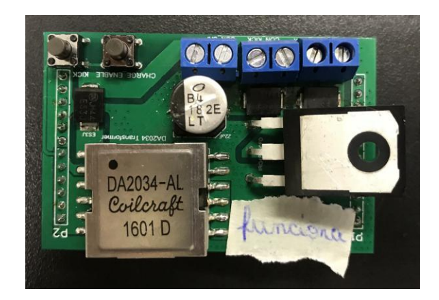
Kicker module In 2018's competition our kicker board circuit has been improved, changing from a simple Boost Converter to a Flyback Converter. The new circuit is controlled by the LT3750 IC, which charges a 2200 µF up to 190V in less than 5 seconds, while the previous board used to take more than 15 seconds to charge up the same capacitor.
The new board has also more debbuging features, as it has a new button connected to the "Charge Enable" pin of the IC, which allows the contol of the charging of the board. The pin is connected to a pull-down resistor and when the button is pressed it connects the battery's voltage to the IC's pin, turning the circuit on while the button is pressed. That is very useful for debbuging, specially when it is done without connecting the board to the robot.
In order to start operating, the Charge Enable pin needs to receive a step input. It initiates a new charge cycle when brought to high or discontinues charging and puts part into shutdown when low. As the board takes approximately 5 seconds to charge up the capacitor, the firmware is programmed to keep sending 6 seconds long step inputs continuously, with a 0.5 seconds gap between them, which is enough to keep the capacitors always charged during the game. It also restarts sending the step inputs every time a kick is executed.
Another improvement on the new board was the adjustment of the gate voltage used for switching the IGBT, as the previous boards had a 7V switching voltage. The new kicker board has a step-up circuit, operated by the MC34063 IC, that charges a tantalum capacitor up to a value between 14V and 16V, depending on the battery's voltage, this voltage is used to drive the IGBT with a IR4427 IC. That was enough for solving the previous board problem concerning the switching of the IGBT, which sometimes caused them to burn. The IGBT used has also been changed to a model with higher current limit ratings, the IGW50N65H5FKSA1, making it even more difficult to burn. Figure 10 shows the new kicker module.
4 Mechanical Project
The mechanical project suffered some changes compared to the previous year's version. Currently, the team is focusing on improving both the robot's efficiency and ease of maintenance. With this in mind, RoboIME is constantly seeking new solutions for the project and through much research and information exchange with other teams, a new dribbler was developed and a new system of kick is being modeled. Below, are described the changes and the planning for RoboCup 2019.
4.1 Development of a new dribbler
From the experiences obtained during the competitions in which the team participated, it was noticed the need to have a better system that would help the robot to have a greater ball control.
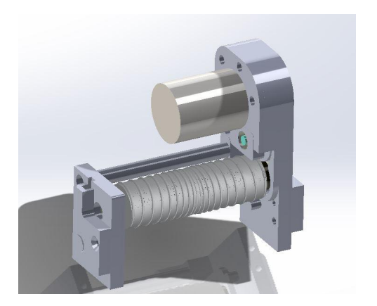
CAD modeling To model the dribbler, SolidWorks was used,aiming the best geometry, great efficiency and suitability for the project.
Transmission system In the previous version an o-ring was used to transmit shaft movement connected to the motor to the roller shaft. However, this did not prove to be an adequate solution for the project, failing to dribble the ball efficiently. So a new dribbler that uses gear transmission instead of the o-ring was designed.
The roller The roller of the dribbler was made using a 3D printed mold and silicon with a catalyst. Many different molds were made in order to test which was the best format. The ideal roller would be able to guide the ball properly to its center. The current one does not succeed in this regard and it has yet to maintain satisfactorily the possession of the ball when the robot rotates. To perform the tests, a Dremel was used to simulate the torque generated by the dribbler's motor.
4.2 The modeling of the new low kick system
Although the low kick worked well during RoboCup 2018, it was possible to see that it could be optimized not only in terms of its geometry but also in the accuracy of the equation of the trajectory previously made.
The decreasing of piston diameter A prototype with a smaller piston diameter was created because the reduction becomes advantageous both by reducing the inertia of the piston and allowing more space for the solenoid, allowing more turns of wire with the same size of external diameter. With this, it is possible to a more powerful kick and more free internal space that can be used for the chip kick solenoid.
Evaluation of the gauge of the solenoid wire No advantages could be seen in using a wire that would leave the kick plate closer to burn, since the permitted speed limit for kicking would be achieved by any of the gauges evaluated (awg 20,21,22 or 23). From the theoretical modeling, it was noticed that awg 23 is the safest, however, with a small difference for awg 21. From tests performed on the robot, it was noticed that awg 21 was the most appropriate considering the speed of the kick and the current that ran through it.
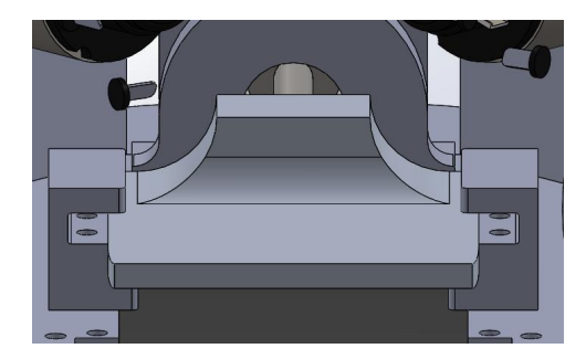
System of guide for the low kick During the tests, a problem was encountered: the kick plate was no longer parallel to the horizontal during the kick. To correct this situation, a system of guides was developed for the low kick as shown below:
4.3 Planning for RoboCup 2019
For the Robocup 2019, the mechanical project will face several improvements, based on flaws found on previous versions. New robots are going to be assembled without reusing parts from the robots that are already assembled and most of the CAD's are going under modifications.
Development of a new transmission system The actual transmission system of the robot's wheels utilizes internal gears, which are not commercial. That makes it difficult and expensive to manufacture them. In order to avoid that, the use of commercial external gears is being considered.
Improvements on the roller of the dribbler The ideal roller is not yet modeled, since the current one still has difficulties guiding the ball to its center and still does not maintain satisfactorily the possession of the ball during rotational movements of the robot. New geometry and materials for the roller are going to be tested until the next competition.
Development of a new kick system The previous geometry of the chip kick didn't work properly so it needs to be modified. It is being considered the use of the same geometry as in the solenoid from the low kick.
Other modifications The position of the battery, capacitor and the power button are going to be changed, in order to provide easier access during the game.
5 Conclusions
For the this competition, the aim is to continue the progress established last year: experimenting a new approach to the software project, modularizing the electrical project and producing more reliable CADs and CAMs in the mechanical project.
5.1 Acknowledgement
This research was partially supported by the Army's Department of Science and Technology (DCT), Fundação Carlos Chagas Filho de Amparo à Pesquisa do Estado do Rio de Janeiro - FAPERJ(grant E-26/111.362/2012); Fábrica de Material de Comunicação e Eletrônica (FMCE/IMBEL) and the companies Altium, SKA and National Instruments. The team also acknowledges the assistance of Clara Luz de S. Santos and Jorge L. de Castilho Jr from FMCE. Special thanks to all former members of RoboIME. Without their support, this team would not be here.
References
- Jan L. L. Segre Lucas O. de Lima Naum A. F. Barreira Victor Bramigk Gustavo C. K. Couto Renan P. Souza Luis D. P. Farias Onias C. B. Silveira Rebeca C. Brito Carlos A. D. Pinto Johnathan F. Rosa Paulo F. F. Rosa. Roboime: on the road to robocup 2016. pages 1–9. Available at https://github.com/roboime/roboime-tdp.
- Carla S. Cosenza Gustavo C. K. Couto Lucas Germano Lucas G. Corra Luciano de S. Barreira Luis D. P. de Farias Luis R. L. Rodrigues Joo G. O. C. de Melo Matheus Bozza Matheus P. de Souza Nicolas S. M. M. de Oliveira Onias C. B. Silveira Rebeca P. dos Reis Renan P. de Souza Sergio G. S. Dias Yugo Nihari Paulo F. F. Rosa. Roboime: From the top of latin america to robocup 2018. pages 1–12. Available at http://wiki.robocup.org/images/1/12/Robocupssl2018-paper34.pdf.
- Carla S. Cosenza Gustavo C. K. Couto Luciano de S. Barreira Luis D. P. Farias Luis R. L. Rodrigues Jan L. L. Segre Matheus C. Castro Nicolas S. M. M. de Oliveira Onias C. B. Silveira Renan P. de Souza Victor Bramigk Yugo Nihari Paulo F. F. Rosa. Roboime: on the road to robocup 2017. pages 1–12. Available at https://github.com/roboime/roboime-tdp.
- Carla S. Cosenza Gustavo C. K. Couto Luciano de S. Barreira Luis D. P. Farias Luis R. L. Rodrigues Jan L. L. Segre Matheus C. Castro Nicolas S. M. M. de Oliveira Onias C. B. Silveira Renan P. de Souza Victor Bramigk Yugo Nihari Paulo F. F. Rosa. Roboime: Team description paper. pages 1–6. Available at https://github.com/roboime/roboime-tdp.
- Jonas Bhlmeyer Daniel Burk Alexander Danzer Stefan Kronberger Christian Lobmeier Michael Niebisch Bjoern M. Eskofier. Er-force extended team description paper robocup 2017. Available at http://wiki.robocup.org/images/0/07/Small_Size_League_-_RoboCup_2016_-_TDP_ER-Force.pdf.
- Manuela Veloso James Bruce. Real-time randomized path planning for robot navigation. pages 1–6. Available at http://www.cs.cmu.edu/~robosoccer/cmrobobits/papers/02iros-rrt.pdf.