RoboTeam Twente Extended Team Description Paper 2019
Simen Bootsma, Lukas Bos, Cas Doornkamp, Koen Hertenberg, Rolf van der Hulst, Barış İmre, Emil Kerimov, Inkeri Kollmann, Thijs Luttikhuis, Freek Nijweide, Alice Petry, Antonio Sanchez Martin, Rob Verbeek, Pepijn de Vos, Selina Zwerver
University of Twente (UT), Enschede, the Netherlands
Abstract This paper presents proceedings of RoboTeam Twente, the Small Size League (SSL) robot soccer team of the University of Twente, intending to participate in the RoboCup 2019 in Sydney, Australia. This paper will focus on the improvements to stability and modularity in the system and the adjustments made to increase ball and robot control.
Introduction
RoboTeam Twente was founded at the University of Twente in 2016 and participated in the RoboCup for the first time in 2017 [1]. The primary goal is to inspire and innovate in the field of robotics and artificial intelligence. Participation in the RoboCup highly stimulates constant improvements in these areas.
This paper presents the technical details of the recent improvements in the software and hardware with respect to the design of the previous year, described in the Team Description Paper (TDP) 2018 [2]. In the following sections, the improvements in motion control, ball control and tactics are discussed as well as findings on using a different robot detection system. All design choices are made to provide a stable and reliable system for the next team and with the thought that other teams are able to adopt parts of the system, making the SSL more dynamic and challenging.
Robot specifications
Robot 3.0 specifications are provided in the table below.
Robot Specifications
| Robot 3.0 | |
|---|---|
| ∅179 × 149 mm | |
| 2160g | |
| 20% | |
| Maxon EC-45 flat 30W | |
| Dribbling motor Comfortably Numb Maxon DCX 19s | |
| rf-370ca-15370 | |
| 55mm | |
| 2:5 | |
| MILE 1024 CPT | |
| 10mm | |
| 71mm | |
| STM32F417VGTx | |
| zForce AIR Touch | |
| LB11697V | |
| 3S3P 11.1V LiPO | |
Electronics
During the 2018 RoboCup it was evident that ball control was insufficient. This was partially due to unforeseen consequences of the electronics design. The main culprits were the motor drivers, which did not allow fine robot control, and the ball sensor, that did not detect the ball accurately in all positions. The improvements regarding these points are addressed in this section.
Motor driver
Previous motor drivers were designed modular to facilitate rapid swapping of faulty circuits. This required drivers of small size and few inputs. The drivers were realised with the DRV10970 IC. This chip, however, limits the output current to 1.5A. It furthermore causes a cut-off at PWM values under 10%. As a result, the robots proved unable to drive at low velocities, causing non-linearity in the system, resulting in poor robot control.
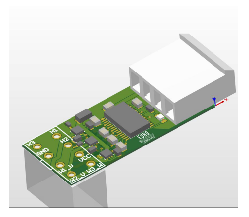
The current motor drivers are designed with equal modularity in mind, obliging size restrictions and using the LB11697V chip [3] as the main motor controller. The drivers can currently deliver twice the current of the previous design, setting a need for external power transistors, which occupy a large area and increase design complexity. This is mitigated by using a combined p and n channel MOSFET. The selected external power driver is the PMCPB5530X [4] p/n channel MOSFET with a small footprint, manufactured by Nexperia.
The resulting circuit has higher and better controlled power output, thereby allowing lower motor speeds, leading to less complicated robot control and quicker reactions to changes in the game. The resulting circuit is shown in Figure 1.
Ball sensor
The previous TDP [2] introduced the zForce AIR Touch ball sensor, which features are listed in Table 2. The sensor is intended to work in addition to the main vision system and supply more accurate data about the position of the ball when it is near the front of the robot. The sensor was implemented, but not used to its full potential due to its position in the robot. This will be further described in Section 4.1.
The sensor runs on customised firmware, as the standard version has a delay of approximately 10ms in active tracking mode and 16-46ms delay when idling. The delay is reduced by assuring the sensor never enters the idle state and ignoring pre-filtering, at the cost of the input accuracy. Additionally, overall quality and speed of measurements are improved by utilising available functionalities of the sensor, such as size filtering, adaptation of the refresh rate and search area reduction. Utilising these capabilities of the sensor, the robot is able to determine the speed of the ball when receiving it and its kicking power can be adjusted correspondingly to ensure more accurate passing and shooting. Ball location accuracy is additionally increased, which can be used to adjust the positioning of the robot for reliable kicking. Shorter frontal vision range limits the extent of acquiring additional ball information.
zForce AIR features
| zForce AIR features [5] | |
|---|---|
| Accuracy | < 7.5 mm |
| Resolution | 0.1mm |
| Scanning frequency bla Max 600 Hz | |
| Search area | 40 mm x 72 mm |
| Interface | I2C |
Mechanics
The current mechanical design focuses on improving ball handling and ball control by incorporating the previous mentioned ball sensor and altering the mechanisms used to kick, chip and shoot the ball. The improvements to those mechanisms are individually discussed in this section.
Ball sensor
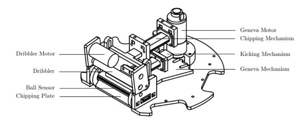
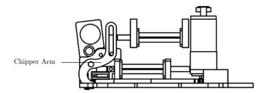
The ball sensor described in Section 3.2 has a maximum frontal vision range of 4cm and 7.2cm sideways. The placement of the ball sensor in the previous design [2] proved to be sub-optimal, since frontal vision of the robot was limited. In the current design, the ball sensor is mounted horizontally, facing the ball at a height just below its middle point, as shown in Figure 2. The ball sensor is placed between two polyoxymethylene (POM) plates that fit into the chipping mechanism. The chipper arms are shaped to curl around the ball sensor (see Figure 3), limiting the sideways vision field by approximately 15%. The chipper structure is rigidly fixed to the bottom plate of the robot for the ball sensor to rest in a stable position.
Ball handling
The plunger for the chipping mechanism is made of POM and the chipper plate of sheet metal. A lever arm is used to chip the ball. To lift the ball, the solenoid plunger is pulled inside the solenoid, meaning the plunger shoots back. The lever arms of the chipper contain a cavity, in which a rod connected to the chipper serves as a linear guide to rotate the chipper arms. A spring ensures that the chipper plunger returns to its original position.
The dribbling structure is hinged to the chipping structure. When accepting the ball, the dribbling structure can slightly rotate, allowing optimal ball reception. Two o-rings are clamped between the dribbling and chipping structure to allow rotational damping. A gear train is added between the dribbling motor and the dribbling bar to optimise the rotational speed and torque transmission.
The plunger for the kicker solenoid is made of POM, meaning the kicking plate is part of the plunger. The solenoid is mounted onto the Geneva plate (described in Section 4.3). The kicker plunger is pushed back into the original position after kicking using springs on both sides, similar to the design by ER-Force [6] [7]. A screw set in the front solenoid mount prevents the plunger from falling out of place.
Geneva
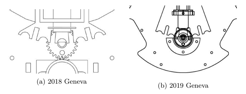
The Geneva mechanism was introduced to the design in the previous TDP [2]. It allows robots to kick the ball at an angle, giving the team an advantage since ball direction is unpredictable. Previously, a motor powered the Geneva drive via a gear train. The thickness of the gears caused grip loss, making the mechanism obsolete. In the current design, the Geneva mechanism is directly driven by the motor, similar to the design of Op-AmP [8]. The comparison between the previous and current mechanism is shown in Figure 4.
Motion control
A crucial feature for a soccer robot is the ability to reach the desired position while avoiding obstacles and maintaining the highest possible velocity. In the previous years, obstacle avoidance used virtual forces [1] [2]. The robot moves in a straight line towards the desired position and when encountering an obstacle, is given an additional velocity vector such that the robot moves around it. This method works sufficiently for small distances and is intuitive, but proved suboptimal. Therefore, motion control is improved by calculating a short, smooth and collision free path in advance. This path is determined using a Voronoi diagram and Bézier Curves.
Voronoi diagram
A Voronoi diagram divides a plane into regions in which each region contains one of the objects that the diagram is generated of [9]. A region consists of all possible points that are closer to the object than to any other object. To obtain a Voronoi diagram of a set of objects, one must construct the Delaunay triangulation [10] and determine the Voronoi diagram using the intersection points of the perpendicular bisectors of the resulting triangles (see Figure 5). The resulting diagram contains a set of nodes connected by segments with maximum distance to objects, along one can construct a safe path from one position to another.
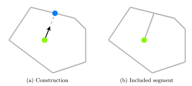
The objects represent the positions of all robots on the field. The objects are, however, not connected to the Voronoi diagram itself. This causes a complication in the next step - the construction of the path (see Section 5.2), that can be solved by creating an additional segment on the existing Voronoi diagram that connects the robot that has to move along the path to a so-called orientation node. The orientation node is the intersection between the orientation vector of the robot and the segment of the surrounding polygon that is in front of this vector (see Figure 6). A similar segment is created for the connection of the ball position to the diagram and in this case the desired end orientation of the robot is used.
![Overview of the construction of a Voronoi diagram [11].](/tdps/soccer_smallsize__2019__RoboTeam_Twente/_page_6_Figure_6.jpeg)
Construct path
The next step is to construct a path using the nodes and line segments of the Voronoi diagram. This path must be simultaneously as short and far away from objects as possible. To compromise between both requirements, weights are given to the segments based on the distance between objects' surrounding segments and orientation. Combined with the distance to the start and end position, a heuristic is created that is used in the path-finding algorithm A* [12]. Compared to other search algorithms such as Dijkstra's algorithm [13], A* is most suitable for this application since it solely propagates towards one target position and does not explore other directions, decreasing calculation duration.
Smooth path
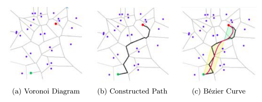
The final step is to smoothen the constructed path to ensure the robot can follow the path with optimal velocity. The smoothing is performed using Bézier Curves as described in [14] since they are easily controlled by placing so-called control points. An important property of the Bézier Curve is that it always lies within the convex hull of its control points, meaning it is guaranteed the curve will not collide with objects, as long as there are none in said convex hull. The control points are placed on the path using Algorithm 1 to satisfy this constraint. This process is shown in Figure 7 in which it is shown that no objects are in the convex hulls of control points.
Algorithm 1 Compute positions of control points
Input: A set of path nodes N
Output: A set of control points C for every curve
1: C ← {}
2: for i ← 0 to N.size do
3: if C.size < 4 then
4: C ← C ∪ Ni
5: else if isObstacleInConvexHull(C ∪ Ni) then
6: P ← Ni
7: while isObstacleInConvexHull(C ∪ P) do
8: P ← (Ni−1+P)/2
9: end while
10: C ← C ∪ P
11: createCurve(C)
12: clear C
13: C ← P ∪ Ni
14: else
15: C ← C ∪ Ni
16: end if
17: end for
Software
Previous competitions showed that the software running robot tactics and decisionmaking processes was neither reliable nor maintainable. Therefore, the entire code base for these processes is rewritten. A new system is designed, which serves as a direct replacement for the old code base and improves the performance of the entire system while simultaneously adding a clear structure that allows future extensions. The new code base can be found on: https://github.com/RoboTeamTwente/roboteam_ai. In this section, the improvements in the robot behaviour are discussed, as well as potential machine learning applications and an alternative robot detection system.
Robot Behaviour
Similar to the previous system, behaviour trees [15] are used as a language to provide tactics and strategies during the game. However, a big change this year is the scoping approach to the trees. Since every branch of a tree is a valid tree, certain branches that represent a specific behaviour or entity are considered 'subtrees'. As explained below, these sub-trees can take the form of role trees, tactic trees, and strategy trees.
Behaviour trees, as before, are constructed of three different nodes. Composites, that have multiple children, decorators, that have a single child, and leafs that have zero children. Naturally, leafs are the skills and conditions that dictate direct behaviour on the robots. The composites and decorators change the flow of execution in the trees and compose different logic using the same blocks. An overview of the control flow nodes is given in Table 3.
Control Nodes in Behaviour Trees [15]
| Composites | |
|---|---|
| Selector | Runs each child in order. If a child is successful, the node is as well. |
| Sequence | Runs each child in order. If a child fails, the node does as well and the other children are not ticked. |
| Parallel Sequence | Runs each child simultaneously. |
| Memory Selector | Equal to Selector, but keeps information about the last tick. Memory Sequence bla Equal to Sequence, but keeps information about the last tick. |
| Decorators | |
| Failer | Runs the child but fails nonetheless. |
| Inverter | Runs the child and inverts the result. |
| Repeater | Repeatedly runs the child for a given amount. |
| Succeeder | Runs the child and always returns success. |
| Until Fail | Runs the child until it fails. |
| Until Success | Runs the child until it succeeds. |
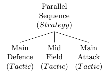
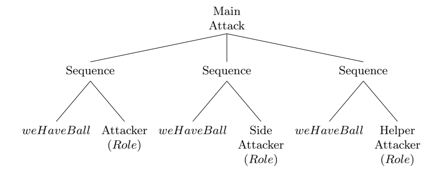
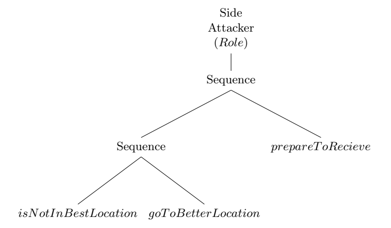
The team behaviour is placed into one behaviour tree called the strategy tree, whose branches are represented in tactic trees (see Figure 8). The latter trees dictate the behaviour of one or more robots that cooperate in a similar role. An example of a tactic could be the attack, in which three robots cooperate in order to score. Before sending robot commands, a decision that dictates the behaviour of one robot must be made. One robot in a tactic tree is represented by a role tree and roles are assigned to the actual robots (see Figure 9). The division of roles over the robots will be discussed further on. An example of a role tree is shown in Figure 10.
Helper Agents
Behaviour trees must be pre-programmed, giving rise to several disadvantages. Each node in a tree is coded and as more effort-intensive adjustments are made, the more error prone and less complete the trees become. The language of the tree is hereby edited each time to suit the needs of the programmer, which is not a good practice. This is why, keeping trees pure is of high priority. Pure, in this context, means keeping the nodes that make up the trees generic for all the situations. Meaning, by only moving and exchanging nodes, all needed behaviour is described.
Therefore, Helper Agents exist alongside the trees where dynamic results can be achieved without the loss of purity. The functions of these agents range from tree assigning, giving optimal positions for specific nodes, to assigning danger scores to opposing robots. Due to the desire to keep trees as pure as possible, the input of the agents is in the form of an integer or vector pair. This will prevent the loss of overview, because only certain parameters are altered and the behaviour remains untouched. The three major helper agents are discussed in this section.
Robot Dealer Behaviour trees assign roles to the robots in a dynamic environment, making it impossible to predict the location of a robot once the game has started. Therefore, it is crucial that roles are assigned accordingly - attacking potential of a robot near its own goal is not optimal, as it would have to move to the opposite side of the field in order to receive a pass during an attack. Similarly, if a robot located on the opponent's side is tasked with defending against an attacking robot with high scoring potential, it is not able to perform properly and effectively. To deal with these situations, Robot Dealer is deployed at the beginning of every game.
Tactic nodes of the behaviour trees can send a request to the dealer, asking for a certain number of robots with specific attributes. As an example, the dealer will be asked for three robots with high attacking potential to execute the Main Attack Tactic. Heuristics to determine these robots are distance to the opponent goal, distance to the ball, and whether the robot is involved in a different tactic already. All robots on the field should be claimed by a tactic, however, fixed number of robots per tactic may increase complexity. To resolve this, tactics are configured to be flexible - a free robot will be claimed as low priority with a generic role, allowing another tactic to overtake this robot if necessary. A generic role is usually placing the robot in a good position depending on the current state of the game.
The Coach The current system uses Blackboards for variable passing. Due to the amount of variables present while playing a game, blackboards can quickly become highly complicated. Additionally, all variables must be programmed inside their trees and inside skills that use those variables, needlessly increasing code complexity.
A new concept is introduced to solve this complexity: the Coach. The Coach is a single instance which is involved in a large part of the decision-making process and returns often-needed locations during the game, such as the location of the ball, goals and robots. In the case of passing, the passBall skill makes a request to the coach, asking to which robot it should pass, on which the coach determines the best option and returns that robot. Furthermore, the Coach notifies the pass-receiving robot that the ball is coming. In every decision there are values that change based on the state of the game, history of what has happened in the game and what is desired to happen. Centralised logic, such as the Coach, allows easier collaboration between robots.
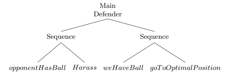
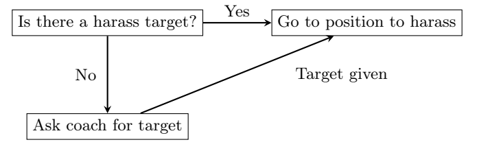
Following example describes a defender tree with snippets from the Coach and the behaviour tree that makes requests to the Coach. Assuming that the opponent robot has the ball, the first Sequence will execute the Harass skill, as shown in Figure 11. To determine which robot to harass, a robot ID is requested from the Coach. The latter, as shown in Algorithm 2, through certain heuristics determines the target robot ID and returns the value to the skill. This interaction is also captured in Figure 12.
ArUco vision
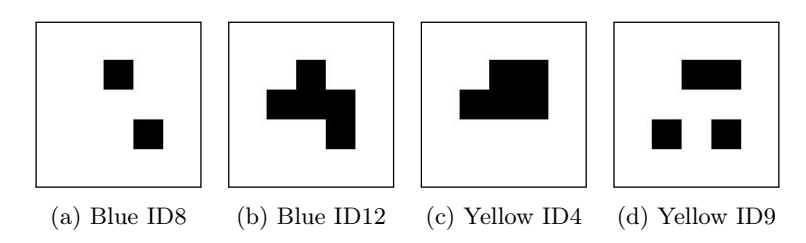
For RoboTeam Twente events outside of the RoboCup, the vision system conditions are less reliable and affect recognition of colour-coded robot markers. The software could therefore benefit from a system which is less reliant on colour distinction. For realisation of this system, robot-markers are designed using only black and white colour scheme (see Figure 13).
Conclusion
This paper described the improvements on the hardware and software of RoboTeam Twente. The adaptations in the electrical and mechanical design, improvements of the motion control and overall increase in stability, reliability and modularity will hopefully lead to success in the RoboCup 2019.
References
[1] RoboTeam Twente. "RoboTeam Twente 2017 Team Description Paper". In: (2017). URL: https://roboteamtwente.nl/documents/RoboTeamTwente_SSL_2017.pdf. [2] RoboTeam Twente. "RoboTeam Twente 2018 Team Description Paper". In: (2018). URL: https://roboteamtwente.nl/documents/RoboTeamTwente_SSL_2018.pdf. [3] ON Semiconductor. LB11696V Datasheet. URL: https://www.onsemi.com/pub/Collateral/LB11696V-D.PDF. [4] Nexperia. PMCPB5530X datasheet. URL: https://assets.nexperia.com/documents/data-sheet/PMCPB5530X.pdf. [5] Neonode. zForce AIR Touch Sensor Specification. URL: https://support.neonode.com/docs/display/AIRTSUsersGuide/Specifications+Overview. [6] ER-Force. "ER-Force Team Description Paper for RoboCup 2014". In: (2014). URL: https://www.robotics-erlangen.de/wp-content/uploads/tdp2014.pdf. [7] ER-Force. "ER-Force Extended Team Description Paper RoboCup 2016". In: (2016). URL: https://www.robotics-erlangen.de/wp-content/uploads/etdp2016.pdf. [8] OP-AmP. "OP-AmP 2017 Team Discription Paper". In: (2017). URL: https://www.robocup2017.org/file/symposium/soccer_sml_size/Robocupssl2017-final9.pdf. [9] F. Aurenhammer and H. Edelsbrunner. "An optimal algorithm for constructing the weighted voronoi diagram in the plane". In: Pattern Recognition 17.2 (1984), pp. 251-257. ISSN: 0031-3203. DOI: https://doi.org/10.1016/0031-3203(84)90064-5. URL: http://www.sciencedirect.com/science/article/pii/0031320384900645. [10] D. T. Lee and B. J. Schachter. "Two algorithms for constructing a Delaunay triangulation". In: International Journal of Computer & Information Sciences 9.3 (June 1980), pp. 219–242. ISSN: 1573-7640. DOI: 10.1007/BF00977785. URL: https://doi.org/10.1007/BF00977785. [11] Ahmed Eldawy. Voronoi Diagram and Delaunay Triangulation. 2015. URL: http://aseldawy.blogspot.com/2015/12/voronoi-diagram-and-dealunay.html (visited on 12/04/2018). [12] František Duchoň et al. "Path Planning with Modified a Star Algorithm for a Mobile Robot". In: Procedia Engineering 96 (2014). Modelling of Mechanical and Mechatronic Systems, pp. 59-69. ISSN: 1877-7058. DOI: https://doi.org/10.1016/j.proeng.2014.12.098. URL: http://www.sciencedirect.com/science/article/pii/S187770581403149X. [13] Huijuan Wang, Yuan Yu, and Quanbo Yuan. "Application of Dijkstra algorithm in robot path-planning". In: (July 2011), pp. 1067–1069. DOI: 10.1109/MACE.2011.5987118. [14] Ji-wung Choi, Renwick Curry, and Gabriel Hugh Elkaim. "Real-Time Obstacle-Avoiding Path Planning for Mobile Robots". In: (2010). DOI: 10.2514/6.2010-8411. [15] A. Marzinotto et al. "Towards a unified behavior trees framework for robot control". In: (May 2014), pp. 5420-5427. ISSN: 1050-4729. DOI: 10.1109/ICRA.2014.6907656. [16] Martin Riedmiller et al. "Reinforcement learning for robot soccer". In: Autonomous Robots 27.1 (2009), pp. 55–73.