2019 Team Description Paper: UBC Thunderbots
Mathew MacDougall, Amy Hashemi, Oon Chu Lip, Chantal Sousa, Hannah Sawiuk, Graham Whyte, Quentin Golsteyn, Red Petzen, Dana Deutsch
The University of British Columbia, Vancouver, BC, Canada
Abstract This paper details the design improvements the UBC Thunderbots has made in preparation for RoboCup 2019 in Sydney, Australia. The primary focus was to rewrite the high-level AI using the Robot Operating System (ROS), and maintaining the performance of our AI from 2018. The secondary focus involved minor improvements to the mechanical and electrical systems for the robots, while developing new components to be part of a prototype robot for next year.
1 Introduction
UBC Thunderbots is an interdisciplinary team of undergraduate students at the University of British Columbia. Established in 2006, it pursued its first competitive initiative within the Small Size League at RoboCup 2009. The team has consecutively competed in RoboCup from 2010 to 2018 and is currently seeking qualification for RoboCup 2019. Over the years, it has made significant developments of its team of autonomous soccer playing robots. This paper will outline the progress in implementation of the current model of robot as well as new mechanical and electrical designs and subsequent modifications in order for the team to compete with a new fleet of robots for RoboCup 2020.
2 Mechanical
This year, the focus for the mechanical team has been to redesign our current robots to accommodate several newly developed mechanical systems which will be implemented in a new fleet of robots for RoboCup 2020. Our primary focus has been to design and integrate a rotating kicker mechanism. To do this the team has been building on and modifying design changes from 2017-2018 as described in our 2017 and 2018 TDPs [1] [2]. In order to accommodate for the rotating kicker major design changes were made to our kicking and chipping mechanism, as well as changes to our motor mounts and drivetrain these changes are outline in detail below. All designs detailed below are currently a work in progress and future plans include prototyping and validation of all systems by RoboCup 2019 followed by a fully functional prototype robot by Fall 2019.
2.1 Rotating Kicker Design
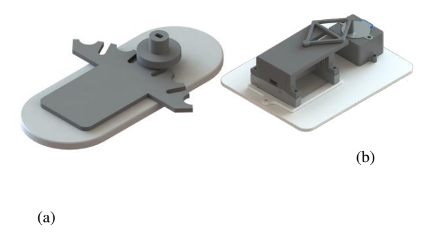
In our current robots we are limited to only kicking and passing linearly as the kicker is stationary and is positioned in the same direction as the robot is facing. Implementing a rotating kicker aims to vary our kicking and passing directions and enhance game strategy. The two potential designs are a motor driven Geneva mechanism, as seen in Figure 2.2a, or slot mechanism as seen in Figure 2.2b, both of which take inspiration from Op amps 2017 TDP [3]. A motor will actuate a plate in the former design or a slot in the latter design, causing the kicker to rotate about a pin located at the front of the robots base plate. The Geneva mechanism plate is designed to rotate a certain amount of degrees per motor rotation allowing for multiple positions for the kicker. The slot mechanism is capable of rotating to any angle within the slot-linker constraint. Currently we are prototyping and testing both mechanisms to decide which design to move forward with. To verify these concepts, we plan on conducting a number of quantitative tests. One is a kicking simulation test which will emulate the force of the kicker via mass-dropping, and allow us to see if the motor torque is sufficient to prevent drifting of the pin during kicking. Another test is to determine the durability of using a ball bearing and shoulder pin at the pivot between the rotating plate and base plate.
For the electrical components of the design we are researching different motors, encoders, and sensors to control and move the mechanisms. These motors include servo, stepper or DC motors. Since one design has a moving plate and one has a moving slot, both of their locations must be known at all times to ensure the kicker is moved to the correct position and within set boundaries. To satisfy this function we have researched encoders and different motors with encoders. The encoder would allow us to track the rotations of the motor and the corresponding position of the rotating plate. However, most encoders would only give us relative position of the kicker. To determine the absolute position of the kicker with these encoders, position tracking using other types of sensors are necessary. We are currently exploring infrared and hall effect sensors as options to solve this issue. The team is also looking into absolute position encoders to see they could be a viable option and solution to this issue.
This design will allow the robots to achieve angled kicking, which in turn give the team an edge on our opponents and allow for the advancement of our gameplay. One example will be the ability to implement curve shots by kicking at an angle and putting spin on the ball with the dribbler.
2.2 Chipper and Kicker Redesign
[This section contains subsections: Overview, Kicker, and Chipper]
2.2.1 Overview
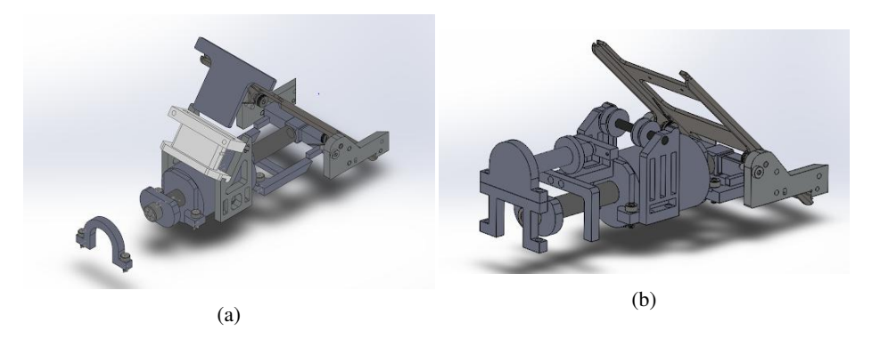
As mentioned in previous TDPs from 2017 and 2018, the current chipper and kickers use of space is inefficient and thus needs to be redesigned so that available free space can be fully utilized [1] [2]. This can be seen in Figure 2.2a. The redesign of both the kicker and chipper is necessary so that one of the rotating kicker mechanisms mentioned above may be implemented. The new designs will also ensure that the kicker can be rotated while the chipper remains stationary. The decision to implement the a rotating kicker meant that the 2018 iteration of the chipper mechanism, shown in Figure 2.2b, would no longer be a viable solution as it interfered with the space on the base plate needed to achieve a rotating kicker [4].
2.2.2 Kicker
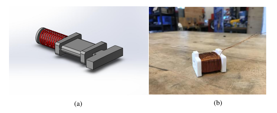
The motivation for the redesign of the kicker was to simplify the design and ensure that no space was wasted. The solenoid shape was changed from a cylinder to a rectangular shape, shown in figure 2.3a, to ensure that it sat more easily on the baseplate and did not take up much space vertically. This also allows for our team to remove the current cutout from our base plate that accommodates for our current cylindrical kicker solenoid. The solenoid shape was also standardized between the kicker and chipper for ease of manufacturing and troubleshooting. Furthermore, the total length was reduced, and the front of the kicker was moved forward relative to the baseplate which allows for ample space in the rear of the robot for a motor to drive the rotating kicker. The new solenoid and kicking bar can be seen in figure 2.3a. These components will sit flush on the flat plate of either rotating kicker design in figure 2.1. The red detailing in the CAD drawing is a return spring and a early prototype of the solenoid can be seen in figure 2.3a. These changes to our solenoids were able to be made since upon calculations based on our current kicking solenoids and their respective travel lengths, it was determined that they were overpowered. Currently our kicking solenoids have the ability to accelerate the ball far faster than the regulation of 6.5 meters per second in 3D space. The newly designed kicker solenoid and travel length aims to be more effective with use of space relative to power, which allows for further innovation.
2.2.3 Chipper
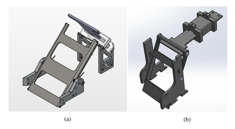
The new design of the chipper actuates the chipping mechanism horizontally rather than our current awkward angled motion in the center cavity of the robot. The current chipping situation can be seen in figure 2.4a and the new design can be seen in figure 2.4b. Further, the new chipping solenoid will now be mounted directly to the middle plate to ensure that the chipper plate will not be moved when the kicker is rotated. The plunger itself is fastened to the chipping plate with a pin slotted in a slot. To chip the ball upwards the solenoid is energized which then pulls the ferromagnetic plunger inwards and this slot accommodates the increase in distance between the pivot point and the plunger). The design of chipper and kicker is designed to consider the dimensions of the dribbler, which has a previously optimized catchment area for a self-centering dribbler. Furthermore, the rectangular cut out located at the bottom is designed in such a way that when the chipper plate is not in use, the kicker will be able to rotate a span of 45 degrees both to the left and right of the resting center position giving the team opportunity to shoot at many angles with accuracy.
2.3 Design of Universal Motor Mounts
The current robot drivetrains are designed to fit within specified dimensions so that it can fit around the dribbler and chipper components. Due to having non-uniform connection points and area available on the base, four different designs of the motor mount are required. However, a problem arises where we need to manufacture duplicates of all types of mounts in case we need to change out a faulty mount on the robot which creates unnecessary complications. Another problem is that the current drivetrain design attracts pieces into the spur gear mesh which causes the wheels to get stuck. A solution that was actively worked on was to change the dimensions of the spur gears through SolidWorks or finding a manufacturer. Our drivetrain goals during 2018 were to make a universal motor mount and to alleviate gear mesh issues.
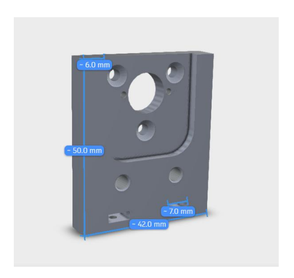
This year, we worked on redesigning the motor mount to create a more space conservative design. Referring to Figure 2.5, we offset our motor placement vertically rather than horizontally with the gears and reduced the space consumption of the motor mounts by 20mm. Because future design goals involve implementing a rotating kicker, our new motor mounts have two placement options for the back two motors allowing flexible motor configuration. In addition, we made the design able to interchange between the 30W and 50W motor. We minimized manufacturing work by designing with standard sizes of sheet metal and screw diameters. The motor mount has a recessed surface around the top half to fit within size constraints but maintain structural integrity near the plates base where the resultant stresses are the highest. In brief, keeping the recessed feature makes the design reversible to work in each position which also reduces time required for maintenance and manufacturing of the part.
3 Electrical
[This section contains subsections]
3.1 Electrical System Redesign
It has been several years since any major hardware revisions have been done for our robots. At this point, our robots are outdated and have begun to place major limitations on the Software team. So, we have decided to redesign the electrical system. The final system is projected to be finished for RoboCup 2020, with major designs finished by the end of this coming summer so they can be integrated into a prototype.
Table 3.1: Comparison of the Old and New Systems
| New System | Old System |
|---|---|
| 7 PCBs, 4 of which are motor drivers 3 PCBs | |
| Modular control board | Integrated control electronics |
| Galvanically isolated HV electronics Common ground between all subsystems | |
| Modular motor driver boards | Integrated motor drivers |
3.1.1 Expected Improvements
- Modular motor driver boards will allow for easier changes in the motors and their connectors.
- Galvanic isolation of the high voltage electronics to improve protection of the control electronics.
- Choices of popular topologies and components to mitigate subsystem obsolescence.
- Decreases in cost and decreases in time spent debugging subsystems due to increased modularity.
3.1.2 Chicker Improvements
To drive the kicker and chipper solenoids, we use a boost converter to charge a 2000µF capacitor bank up to 240V. The stored energy is then used to actuate the chipper and kicker mechanisms by the controlled discharge of the capacitors into the solenoids via IGBTs. The solenoid driver PCB, the Chicker board, functions well; however, the low voltage control electronics and the Chicker board are not galvanically isolated. This lack of isolation has caused large amounts of damage to our robots and has cost us time and money. We are attacking this issue from three sides: creating a safe mechanism to discharge the capacitors in the event of an emergency, developing a testing platform for the Chicker board, and then redesigning the Chicker PCB.
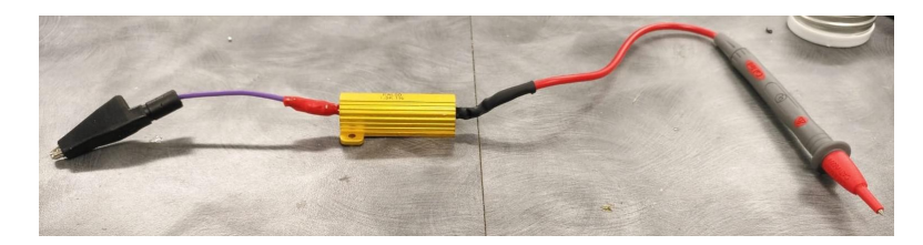
The capacitor discharge tool drains capacitors slowly, which prevents damage to our system in the event that a capacitor disconnects from one of our PCBs. Using this circuit safely discharges the capacitor in 7.5 seconds at peak charge. The circuit consists of a 1.5 kΩ resistor rated for 50 W (larger than the power when the capacitors are at peak charge: 38.4 W), an alligator clip to connect to the chassis ground, a multimeter probe to connect to the positive terminal of the capacitor, and 14 AWG copper wire.
3.1.3 Chicker Testing Platform
Due to the current setup, the Chicker board can only be tested on a fully assembled robot. This puts the rest of the system at risk of damage or destruction every time we want to test a PCB. To mitigate future losses, a testing platform is currently being designed that will allow for the Chicker boards to be tested individually. We are currently in the process of developing and validating firmware to drive the Chicker board as well as developing automated tests to validate the functionality of the PCBs. The functionality of the platform will also be extended to include testing of newly wound solenoids that we make in house to allow for full validation of the solenoid driver system before integration.
3.1.4 Chicker Board Redesign
As mentioned above, the lack of galvanic isolation between the HV and LV subsystems continues to cause damage to our robots. In the new design, the HV and LV components will be galvanically isolated through the replacement of the standard boost converter with flyback boost converter. Since the power planes will be isolated, the signals used to drive solenoid actuation cannot be directly fed into the Chicker board. So, a combination of digital optocouplers and linear isolation amplifiers will be used to facilitate communication across the isolated planes. The digital optocouplers will be used for the discharge signals (chip and kick), whereas their linear counterparts will communicate the capacitor bank voltage. The last major change to the PCB is the IGBT drivers. Instead of half-bridge low-side driver ICs, we will use a Darlington transistor to efficiently drive the IGBTs which are connected to the solenoids.
3.1.5 Power Distribution Module Redesign
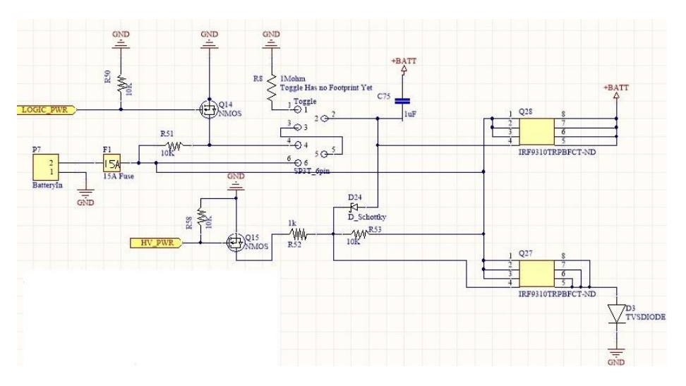
We currently use a switch with an SP3T OFF-ON-MOM topology to direct the supply of power. It works as follows:
3.1.5.1 OFF
- Pins aligned 2-3, 5-6
- Gate of Q28 P-channel MOSFET pulled to +BATT, so $V_{GS} < -V_{TH}$. Therefore the MOSFET is in its cut-off region and no current flows.
- Source of Q27 is pulled to +BATT and D24 becomes forward biased. This causes the gate of Q27 to be pulled to +BATT, placing Q27 in the cut-off region.
3.1.5.2 ON
- Pins aligned 2-3, 5-4
- Q28 and Q27 under firmware control via Q14 and Q15, respectively.
- If HV PWR is high, D24 becomes reversed bias, creating a voltage divider via R53 and R52. This causes $V_{GS} > -V_{TH}$, placing Q27 in the saturation region.
3.1.5.3 START
- Pins aligned 2-1, 5-4
- 2-1 connection pulls downs the gate of Q28 via R8, which places it in saturation.
- With the gate of Q28 pulled low, Q27 is under firmware control via Q15.
Although the system works well, the OFF-ON-MOM switch topology is essentially obsolete and we have been unable to find a similar switch for a few years. To resolve this issue, we have decided to choose a switch with a more popular topology and integrate it into a new modular power distribution PCB for next years fleet of robots.
The current system works as following: when in the ON state, power is distributed to the control electronics as well as the high voltage solenoid driver board. When the switch is put in the MOM state (MOM=momentary ON, the switch goes back to the START position immediately after), the motors are given power (start state). The most popular switch topologies on are ON-OFF-ON and ON-ON. Because it is desirable to have both an ON and a START state for safe testing, we chose the ON-OFF-ON topology. This way, one of the ON states can be used for bootloading and testing in which the Chicker board (solenoid driver) and the motors are not given power. This ON1 state will be used to test to independently test the control electronics. Then, the entire system will be given power when switched to the ON2 state. We are currently in progress of laying out the schematic.
3.2 FPGA Upgrade
The FPGA on our robots is used for PWM generation for the motors, reading the accelerometer, gyroscope, and hall sensor data, as well driving an inter-chip bus and interrupt controller. The current generation of robots utilize a Xilinx Spartan-6 FPGA. This FPGA is no longer actively supported by Xilinx and is challenging to develop on. In addition, the HDL code is all written in VHDL, which is no longer part of the core curriculum for both the Computer Engineering and Electrical Engineering undergraduate programs as Verilog is taking precedence. As a result, we are moving to a Xilinx Spartan-7 FPGA and then porting the HDL code to SystemVerilog since the synthesis tools for this FPGA support not only Verilog and SystemVerilog, but also multi-language synthesis and simulation. We hope these changes will allow us to better make use of the FPGA and enable younger team members to contribute.
4 Software
[This section contains subsections]
4.1 New Software Architecture
The main focus of the software team this year has been designing and implementing an entirely new software architecture. With our current codebase approaching almost 10 years old and accumulating significant technical debt, we decided it was time to take all lessons learned from the current system. As such, we have implemented a new, more modular, and more robust system, all whilst removing technical debt. In addition, we took this opportunity to add additional documentation to make the entire codebase and architecture more maintainable for future generations of our team.
Our new software architecture makes use of the Robot Operating System (ROS). ROS is a framework that allows multiple standalone executables (called nodes) to be run simultaneously and communicate using a TCP/IP protocol. This communication occurs over topics, which act as named buffers that the nodes can publish and subscribe to. This allows multiple nodes to transmit and receive information from one another asynchronously. RoboTeam Twente describes ROS and its benefits in greater detail in their 2017 TDP [5].
When considering different frameworks to help us make our new architecture more modular, ROS was a clear choice because of its inherently decoupled nature. We are able to separate functionality into different nodes, with well-defined interfaces between them using the ROS messages. This more modular software structure makes it easier for more members to work on the system in parallel, without making conflicting changes. As RoboTeam Twente mention in their 2017 TDP, these well-defined interfaces make different nodes interchangeable [5]. For example we can have one node that is responsible for communicating with grSim, and a separate node that is responsible for communication with our robots via radio. In this case, as long as both nodes expose the same interface and accept the same commands, we can use these communication nodes interchangeably depending on if we want to use the simulator or our real robots.
Furthermore, ROS provides several other useful features that are commonly implemented by SSL teams. The first of these is logging. ROS provides a rosbag utility that allows all the communication between the nodes in the system to be recorded. These recorded messages can then be played back to the system at a later date, to simulate the communication in real-time. This playback feature allows for superior integration testing of the system. Nodes can be tested separately by replaying a set of recorded messages, and validating the node performs as expected. Additionally, this can be expanded to full game playbacks. The communications can be recorded during a RoboCup for example, and then played back to the system later on. This will allow the AI to run as it was during the game, and developers can break and debug at any point they choose to understand why certain behavior occurred. The second useful feature is the ROS Parameter Server. The ROS Parameter Server is essentially another node that can store public values that the rest of the system can access by making API calls. What is particularly useful about this system is the ability to modify values at runtime and have the changes be reflected across the entirety of our system, even across different nodes. This makes it trivial to modify and tune constants and parameters at runtime, an invaluable ability that dramatically speeds up real-time testing and debugging. These runtime parameter values will also save a significant amount of time during games, allowing us to make changes to our AI during a timeout without having to re-compile (a process that can take a non-trivial amount of time in certain cases).
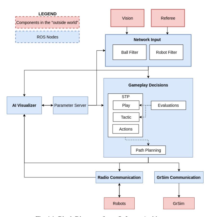
Below, in Figure 4.1 is a high-level diagram of our new software structure. The arrows show the flow of information over ROS messages via topics. The dashed lines show the flow of information within the nodes.
Our new architecture contains many of the core components of our old system, simplified and separated into nodes. The Network Input node is responsible for handling all data received over the network, including SSL Vision and Refbox data. This data is filtered before it is sent to the rest of the system [4].
The Gameplay Decisions node contains the Skills, Tactics, and Plays (STP) structure used previously, and the path planning module [6]. The path planning module utilizes both the Rapidly-exploring Random Tree (RRT) algorithm as well as a Bezier path planner [4].
The GrSim Communication node is responsible for all communication with GrSim. It accepts the same robot Primitive commands, and simulates our robot firmware and motion controller before sending protobuf commands to the robots [4].
Similarly, the Radio Communication node accepts robot Primitives, serializes them into radio packets, and sends them to our radio dongle over USB [4].
Finally, we have separated our Visualization tool into its own node. Like many teams, our visualization module allows us to display what the AI is seeing and control it. Our Visualizer has also been rewritten and is significantly different this year, and is explained in greater detail in the following section.
To further increase the separation of concerns in our new code, we adopted a more functional style of programming where modules and functions return their results rather than continuing to call functions and mutate values. Not only did this make it much easier to write smaller, well-defined modules, it also made them significantly easier to test. Most notable, our Skill, Tactic, and Play classes now return Primitives rather than calling functions all the way down the stack until a Primitive is sent to the radio, which now enables testing that was impossible before. Other modules that significantly benefited from this change were the path planner and navigator.
Last of all, we feel this new architecture could be a great starting point for new SSL teams, as well as for those interested in using the ROS framework. As such, we have now open-sourced our code, which can be found at https://github.com/UBC-Thunderbots. We are hoping to make more contributions to the SSL opensource community in the future, and are looking forwards to collaborating with other teams.
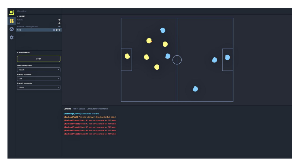
4.2 New Visualizer
Like many teams, we have a GUI that allows us to visualize the internal state of our AI, and control it. For example, starting and stopping the AI, setting our team color, and setting various parameters. Traditionally, our GUI was written is C++ and heavily tied to the rest of our system through GLib signals. Now, we have chosen to separate it into its own node in the ROS system. This gives us the flexibility of using any language we want that supports ROS, and it can easily be changed again in the future without affecting the rest of the system.
As data visualization is the primary focus of this module, we decided to develop it as a web application to take full advantage of UI driven technologies such as SVG and CSS. In addition, the large web development community allows us to rely on many open source projects to support the creation of the visualizer. One of these projects is React. React is a library for building user interfaces. Historically, web development was difficult due to the inherent challenge of syncing the application data with its view. React offers a series of abstractions to hide this complexity. The management of our application state is handled by another JavaScript library called Redux. Redux defines a clear workflow to update the applications data and offers a high level of modularity in the data management of the visualizer.
Communication between ROS and the visualizer is accomplished via the rosbridge framework, a ROS to JSON data-layer. ROS messages are captured by rosbridge and converted into JSON before being sent to the application via a websocket.
We expose a drawing interface in the AI portion of the project. The AI can request various shapes to be drawn in the visualizer based on what it is currently seeing. Shape information is then sent via ROS messages to rosbridge, converted to JSON, and sent to the visualizer. The data received from rosbridge is then used to create an SVG graphic, effectively rendering what the AI wants to display. This decoupled approach, where the visualizer has no context as to what it is drawing, enables members to add new visualization layers based on the needs of the AI without requiring any changes to the visualizer itself.
4.3 Optimizing Robot Role Assignment
Our High-level decision making uses Tactics from the STP decision-making structure [6]. These tactics represent single-robot roles on the team, such as the goalie or a defender, and are continually assigned to robots as the game is played.
In the past, we used a greedy algorithm to assign tactics to the available robots. Each tactic defined a function to select the most preferred robot from a list. In order of priority, tactics would choose their robot, and robots would be removed from the list as they were chosen. This resulted in the highest-priority tactic always getting the robot it wanted and the lowest-priority tactic being stuck with whatever robot was left over.
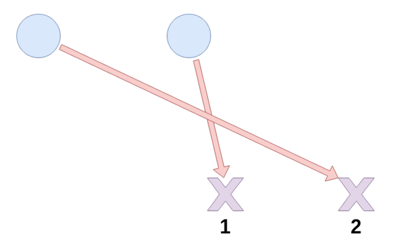
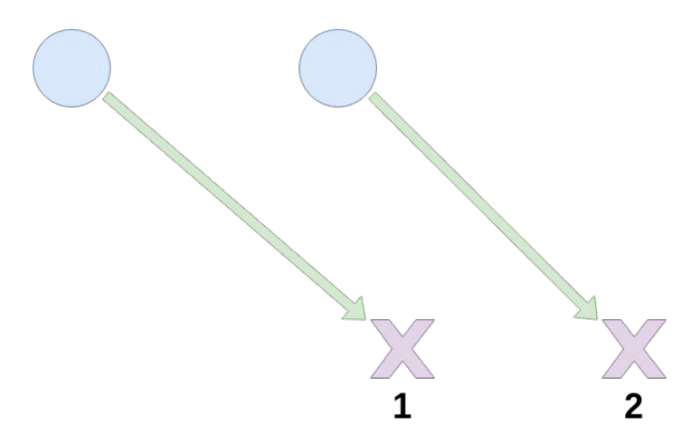
However, this greedy algorithm led to very sub-optimal assignments in some cases. Robots could be made to cross paths, and the tactic with the least priority could be paired with a robot very far away, even when closer robots are available. Figure 4.3 shows one such case, where the blue circles indicate the robots, the desired destinations of some tactics are indicated with purple Xs (labeled with their priorities), and the pairings of robots to tactics are shown with the arrows. Using the greedy approach, the first tactic will chose the robot closest to it, forcing the second tactic to be paired with the remaining robot.
To solve these issues, our new approach performs global optimization across all robot-tactic pairings. Rather than the previous select robot from list function, tactics now implement a function that returns the cost of assigning a given robot to the tactic. These costs are typically correlated with how far away a robot is from a tactics desired destination, but this system allows tactics to be flexible about how they evaluate the cost of a robot.
These cost functions are then used to construct a matrix containing the cost of assigning every robot to every tactic. We use the Hungarian Algorithm with this matrix to find the pairings of robots to tactics with the lowest overall lowest cost. The Hungarian Algorithm performs this optimization in polynomial time, $O(n^3)$, which performs significantly better than a brute-force search through all the possible combinations, which would take a factorial amount of time with respect to the number of robots [7].
By using global optimization, we were able to successfully avoid the sub-optimal cases we observed before. Compared to before, we see far fewer cases where robots cross paths, and because the distances between robots and their destinations are now more similar the entire team is able to move into position more quickly.
4.4 Integration Tests with GrSim
With test-driven development being a large focus with our new software architecture, we are adding new simulated integration tests using GrSim. This is very easy to achieve with the new architecture. Since grSim provides a grSim Replacement protobuf message, we can programmatically set the positions and velocities of the robots and ball. This allows us to create any initial state of the field we want to test with. Then we can run our AI for a predetermined amount of time, and validate that the correct decisions were made based on the initial state and that the robots ended up in the correct locations. For example, we could place the enemy robots and ball in a threatening position, and validate that our robots correctly moved to the most optimal defensive positions.
This provides a great way to have automated integration tests run as part of our CI pipeline. We can validate that our AI will make roughly the same decisions in the same scenarios, so that we dont accidentally change our gameplay behavior while making other changes. We can also be sure that all the components of our system are correctly working together, from data filters to path planning.
5 Control
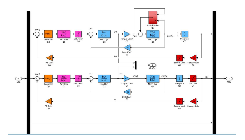
To control the movement of our bots, we use a Bang Bang controller, also known as a hysteresis controller. The controller works, however, it is quite flawed and limiting.
In the last year, we have developed a model for the motors, but firmware has to be written and extensive tests have to be done with the robots to adequately tune the PID constants. We are in the process of extending the model to include the entire robot so that we can test it against the current Bang Bang controller. We will use the Bang Bang controller to create baseline measurements for different maneuvers and then compare it against the PID controller to benchmark the performance of the PID controller.
6 Conclusion
We believe that the design changes detailed above will lead to significant improvements in performance. We look forward to putting the changes into action at RoboCup 2019 and 2020.
7 Acknowledgements
We would like to thank our sponsors, as well as the University of British Columbia, specifically, the Faculty of Applied Science and departments of Mechanical Engineering, Engineering Physics, and Electrical and Computer Engineering. Without their continued support, developing our robots and competing at RoboCup would not be possible.
References
- C. Y. Bai, W. Gong, B. Hers, B. Hsieh, R. De Iaco, Y. Z. Ju, B. Jury, B. Long, K. L. Lu, J. Petrie, K. Tonks-Turcotte, C. Xie, D. Yang, R. Zaari, K. Zhang, and K. Zhang, "2017 Team Description Paper: UBC Thunderbots," 2017.
- A. Buonassisi, O. Chu Lip, D. Deutsch, G. Ellis, E. Goto, A. Hashemi, N. Ivanov, E. Jackson, K. Lai, M. Lee, Q. Li, M. MacDougall, J. Petrie, K. Tonks-Turcotte, C. Sousa, and B. Xu, "2018 Team Description Paper: UBC Thunderbots," 2018.
- T. Yoshimoto, T. Horii, S. Mizutani, Y. Iwauchi, Y. Yamada, K. Baba, and S. Zenji, "OP-AmP 2017 Team Discription Paper," 2017.
- S. Churchley, R. De Iaco, J. Fraser, S. Ghosh, C. Head, S. Holdjik, N. Ivanov, S. Johnson, F. Kalla, A. Lam, B. Long, K. Lu, S. Ng, K. Peri, J. Petrie, E. Roach, W. Y. Su, B. Wang, C. Xi, K. Yu, and K. Zhang, "2015 Team Description Paper: UBC Thunderbots," 2015.
- E. Croll, R. Freije, K. de Haan, H. van der Heide, J. Hoekstra, B. Okken, R. Plompen, B. Rubbens, R. Timmer, S. Tolboom, D. de Weerdt, I. Weijers, and W. Westra, "RoboTeam Twente 2017 Team Description Paper," 2017.
- B. Browning, J. Bruce, and M. Veloso, "Stp: Skills, tactics, and plays for multi-robot control in adversarial environments," Proceedings of the Institution of Mechanical Engineers, Part I: Journal of Systems and Control Engineering, vol. 219, no. 1, p. 3352, 2006.
- "Hungarian Algorithm," https://en.wikipedia.org/wiki/Hungarian_algorithm.