URoboRus 2019 Team Description Paper
Anastasiia Kornilova, Petr Konovalov, Galina Reneva, Dmitrii Iarosh, Irina Khonakhbeeva
Saint Petersburg State University, Saint Petersburg, Russian Federation
https://en.wikipedia.org/wiki/Uroborus · https://trikset.com · http://blog.trikset.com/p/eng.html · https://vk.com/roboschool_vlg · https://robofinist.org · https://www.qt.io · https://www.mathworks.com/products/matlab.html · https://github.com/robocup-ssl-russia/LARCmaCS · https://github.com/RoboCup-SSL/ssl-vision · https://github.com/robocup-ssl-russia/MLscripts · https://developers.google.com/protocol-buffers · https://www.mathworks.com/help/matlab/matlab_external/engine-c-api-1.html · http://wiki.robocup.org/images/9/96/Small_Size_League_-_Standard_Pattern_2011.pdf · https://visualstudio.microsoft.com/ru/vs/features/cplusplus · http://www.mingw.org · https://travis-ci.com · https://bitbucket.org/verateam/vera/wiki/Home · https://www.mathworks.com/products/compiler/matlab-runtime.html
Abstract URoboRus is a team from the Saint Petersburg State University (Russia) developing a solution to participate in the RoboCup Soccer Small Size League. This paper presents the technical overview of our robots, control software system and main algorithms. It will be the first participation in this competition, consequently, a full description of all components is provided.
1 Introduction
Our team unites passionate students from departments of Software Engineering and Theoretical Cybernetics (Control Theory), and evolves with a support from initiative faculty members of these departments. Also, our project is supported by CybetTech Labs Co Ltd, a company behind the educational robotics kit TRIK, which is widespread in Russian schools. We started to create our solution in September 2018 on the basis of robots, which were developed by third-party company on our request, and at the moment of writing we have implemented a framework for robots control and a library with general algorithms. By April-May 2019 we plan to support a full game by Robocup-SSL rules.
Successful participation in the professional Robocup-SSL league and consequent improvement of hardware and software are not the only aims for us. Related goals also include popularization of this competition in Russia, development of solution for educational robotics, which is affordable for schools and universities, and in the future – organization of local Robocup-SSL league in Russia. While reading this article one will see some solutions which have been done in this direction. For example, a porting of an SSL-Vision to Windows is in process, an attempt to make our control system cross-platform are being made too, furthermore opportunities for different interpretation engines (i.e., Python) are being considered. As of January 2019 we have already organized a hackathon for students at the Russian inter-university robotics school and have participated with our setup in the international robotics festival "Robofinist".
2 Robots description
As it was mentioned in introduction, robots, which we use, were made by thirdparty company by technical specification, so in the section we provide a description of this specification and some details about its implementation. All information about mechanical and electrical design can be found in our repository.
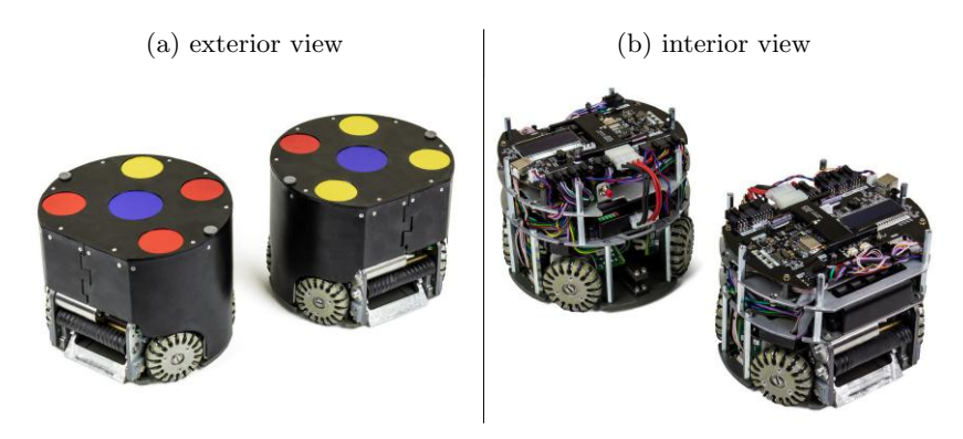
The robot consists of a straight kicker, a chip kicker, four omnidirectional wheels, and a ball spinning device (dribbler), which is equipped with a ball presence sensor. The robot has inertial sensors and a Wi-Fi transceiver for communicating with the control software. An LCD screen is installed on the robot's motherboard and displays the name of the current Wi-Fi network and robot IP address in this network. The robot is equipped with a USB service interface to change internal parameters and restrictions. Each device is controlled by a separate board, that simplifies the process of diagnostics and repairing.
2.1 Main technical characteristics
All main technical characteristics can be found in the Table 1.
Battery: The robot is equipped with a removable battery with a capacity of 3000 mAh and an average voltage of 26 volts. The operation time is ≈30 minutes with an average current consumption of 6A. In order to charge the battery, it should be preliminarily removed out of the robot. The battery is equipped with a balancing device, as well as a protective device against overheating, short circuit, deep discharge and overcharge. It also has a charge level indicator on the front panel.
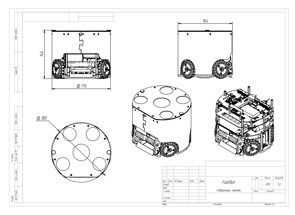
Table 1: Technical characteristics
| Dimension | Value |
|---|---|
| Dimension | diam. 180 * 146mm |
| Total Weight | 3,5kg |
| Max Ball Coverage | 19% |
| Driving Motors | Maxon EC 45 Flat 70W |
| Gear | 18:60 |
| Gear type | internal spur, cyllindric |
| Wheel Diameter | 57,1mm |
| Encoder | Encoder MILE, 1024 CPT, 2 Channels, with Line Driver |
| Dribbling Motor | Maxon EC MAX 22 |
| Dribbling Gear | 50:30 |
| Dribbling bar | diam. 17 |
| Kicker Topology | Fluback converter (UP to 290V) |
| Chip Kick distance | 2,5m |
| Straight kick | not tested |
| Main Controller | STM32F407VG |
| Battery | "Open Robotics", 7S 3AH Battery with integrated BMS |
| Motor Drivers | "Open Robotics", 5 X BLDC Motor Driver |
| Sensors | Encoders, IMU , Ball Sensors |
| Communication link | ESP8266 |
Connection: Connection with robot can be established via 2.4G Wi-Fi and it receives IP address automatically from DHCP. Protocol of communication with robots is defined in the Robot communication module section.
Motors: The robot is equipped with four mid-flight brushless motors for omnibase and one more "dribbler" brushless motor to spin the ball. The motor control method is vector control with current control in the windings and limiting the maximum torque on the rotor. Every engine is served by a separate driver board with a microcontroller.
Robot control: There is a special coordinate system associated with robot. So that the robot starts to perform actions, a special UDP packet with parameters should be sent to the robot. Movements of the robot are controlled by using SpeedX (speed along axe X), SpeedY (speed along axe Y), SpeedR (angular speed of the robot). To kick ball, paramaters Kick-up or Kick-forward should be set. For more details see in Robot communication module section.
3 Control software
This software was developed by using C++ with Qt framework; this choice was partly motivated by its cross-platform nature. Software implementation of the algorithms was performed by using Matlab, partly due to its convenience at the stage of prototyping.
Our software system basically consists of the following two parts:
Centralized control tool is commissioned to solve the following tasks:
- collecting data about field geometry and game situation from robots and SSL Vision
- providing this data to the Matlab algorithm library, which calculates control signals for robots
- transmitting those signals to the robots
Matlab algorithm library provides to analyze the situation in the field and to assign the current roles to the robots based on this analysis. This library is also used by the Matlab Engine to calculate control signals to every robot with regard to its currently assigned role.
An overview of modules and their interaction is illustrated in the software system diagram.
3.1 Centralized control tool
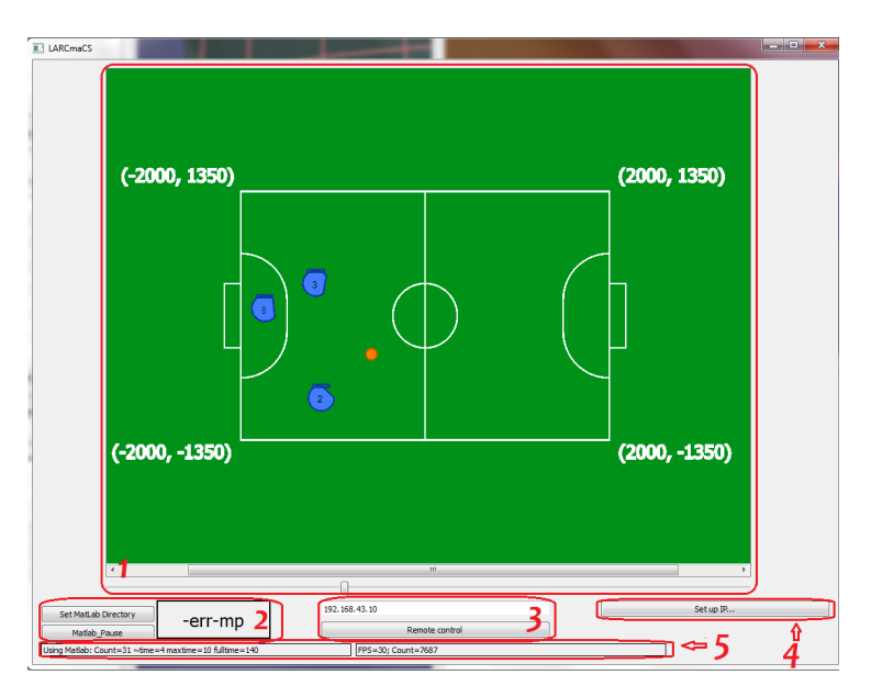
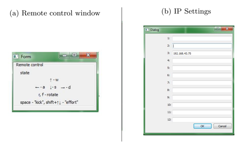
The connection with SSL server is established through SSL receiver module, which distributes the received data among all other modules. Centralized control tool sends commands to robots via Robots communication module. These commands are evaluated by Matlab engine and collected by Matlab communication module. UI module is responsible for graphical user interface which displays situation in the field and allows operator to start some algorithms in test mode or control robots manually.
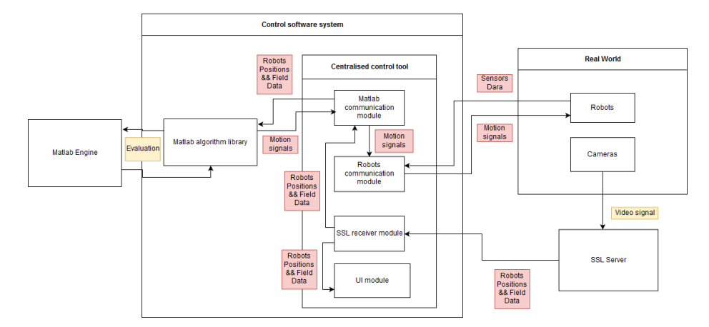
Fig. 4: Structure of packet received from the robot
| Robot packet | 0-3 | 4 | 5-8 | 9-12 | 13-16 | 17-20 | 21 | 22-25 | 26-29 | 30-33 | 34-37 | 38-41 | 42-45 | 46-49 |
|---|---|---|---|---|---|---|---|---|---|---|---|---|---|---|
| Numbers of bytes | Synchronizing block 0xAA 0xAA 0xAA 0xAA | Ball sensor | 1st quaternion element | 2nd quaternion element | 3rd quaternion element | 4th quaternion element | Kicker charge status | Voltage | IP | left inertial sensor x | left inertial sensor y | right inertial sensor x | right inertial sensor y | CRC32 |
When Robots communication module receives control signals from Matlab communication module, it converts them to the special UDP datagram packets (called "Control packets"), where:
- Speed X value from -100 to 100, which indicates percentage of power for motors to move robot along the x axis of its coordinate system
- Speed Y value from -100 to 100, which indicates percentage of power for motors to move robot along the y axis of its coordinate system
- Speed R value from -100 to 100, which indicates percentage of power for motors to rotate robot (positive value means clockwise rotation of the robot)
- Dribbler speed value from 0 to 100 which indicates power of dribbler motor in percentages
- Dribbler enable flag byte which indicates that dribbler should be turned on/off
- Kicker voltage level value from 0 to 30 which indicates power of next kicking action (kicker needs time for charging to be ready for kicking)
- Kicker charge enable flag byte which indicates if kicker charging should be started or not
- Kick up byte which indicates if chip kicker should be activated
- Kick forward byte which indicates if straight kicker should be activated
- CRC32 control sum which was calculated using algorithm CRC32
and then transmits them to robots.
Matlab communication module: This module is responsible for launching Matlab engine, transmitting coordinates of objects on the field to Matlab Engine and extracting control signals for robots from engine after evaluation. We use Matlab C++ Engine API library for getting access to Matlab engine from C++ source code. To underpin calculation of control signals we transmit the coordinates of the ball and robots, as well as sensors parameters to Matlab engine, and then evaluate file "main.ml". During evaluation special structure "Rule", which keeps control signals for robots, is initialized. After evaluation this structure is exported from Matlab engine and sent to Robot communication module.
3.2 Matlab algorithm library
As it was mentioned in section Matlab Communication module, general scheme of robots control consists of the next steps:
- receiving new SSL packet with data about robots (Yellows, Blues) and ball (Balls) positions on the field and loading them to the Matlab engine
- main.ml evaluating, during which a special structure "Rule" with control signals is being filled
- pulling this structure out and sending control signals to the robots
There are 5 variables which are shared between Centralized control tool and Matlab algorithm library – Blues, Yellows, Balls, Rule, ballInside. The first three variables describe data from SSL, the fourth one contains control signals for robots, the last one defines is ball inside any robot or not. All this variables are declared as double array (except ballInside, which is double scalar), both C++ and Matlab.
At the beginning of "main.ml" evaluation all needed variables and structures are initialized by using mainHeader function. During this function global structure RP are declared by using loaded data from SSL. This structure will be shared between all algorithms in the future evaluation. Structure RP contains the next main fields.
- Blue array of structures with information about blue robots (robot presence on the field, robot position, robot angle)
- Yellow array of structures with information about yellow robots (robot presence on the field, robot position, robot angle)
- Ball structure which contains information about ball position
- Pause flag which controls stopping and starting of evaluation
- Rule array of structures with control signals for robots
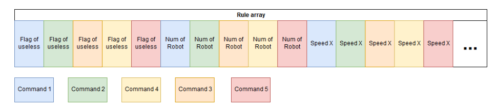
During evaluation "RP.Rule" should be filled with calculated control signals. Rule has the next fields:
- "Robot in use" flag controls do we need to send control signal to this robot or not
- Number of robot number of robot according to SSL Pattern
- Speed X robot speed along X-axe of its local coordinate system
- Speed Y robot speed along Y-axe of its local coordinate system
- Kick forward flag controls should robot kick forward
- Speed R robot angular speed
- Kick up flag controls should robot kick up
3.3 Build configurations
Compilers: Initially, the project was developed for Windows platform only for the sole reason that then it would be easily accessible by school students. This motivated us to choose MSVC-compiler for our application. Our current objective is to remaster the software for running on Linux. As a first step to this end, we have already converted the core programs to the to MinGW-compiler. Our software system can be compiled by both of these compilers for Windows platform at this moment.
Architectures: Our application needs Matlab. So as not to impose a restriction on the bit-version of the Matlab, both Matlab x64 and Matlab x86 were supported.
Continuous Integration: Travis CI with static code analyzer Vera++, which automatically checks codestyle of pull requests, is used for automatic tests. Although Matlab is needed for running our software system in full, but for testing build process of the project and running it, the testing build process calls for only Matlab Runtime Compiler, which is in free access. Our plans include transition from Matlab to MRC in order to make our software independent of any commercial products.
SSL: At the moment we have to support our Centralized control tool with two versions of SSL-vision: old (2012 year) and new (2018 year). The old version is available on both Windows and Linux, while the new version is only available on Linux. We actively use the old one, because of more convenient way to deploy our setup. At the moment we actively try to port new SSL-vision to Windows.
4 Algorithms
The developed algorithms can be categorized into three groups: basic algorithms, advanced algorithms and roles (behaviour patterns). Now we illustrate every group by describing its most important algorithms.
4.1 Main terms
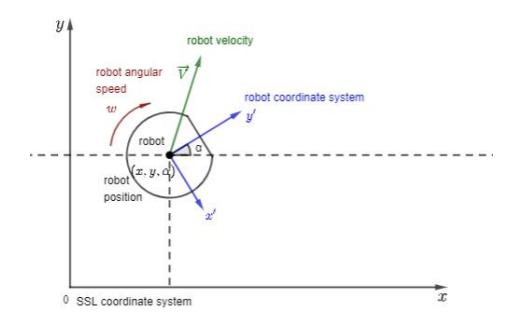
- SSL coordinate system – global coordinate system associated with data received from SSL-vision
- Robot coordinate system local coordinate system associated with robot control model
- Robot position consists of the Cartesian coordinates of robot center and the polar angle of robot in the SSL coordinate system – (x, y, α)
- Robot velocity is a vector of velocity in robot coordinate system $\overrightarrow{v}$
- Robot angular speed is angular robot speed $\omega$
- Minimal robot speed is a minimal speed at which robot starts to move $v_{min}$
- Minimal angular robot speed is a minimal speed at which robot starts to rotate – $\omega_{min}$
- P, I, D are the proportional, integral, and differential coefficients of the considered PID-controller
4.2 Basic algorithms
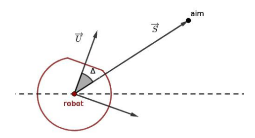
MoveToPoint: This algorithm controls robot's moving to the destination point.
Input: robot position, destination point.
Output: robot velocity.
P-controller is used to calculate the magnitude of robot velocity:
$$V = V_{min} + P \cdot |\overrightarrow{S}|$$
To translate direction vector $\overrightarrow{s}$ to robot coordinate system we use the next formulas:
$$\overrightarrow{s} = \frac{\overrightarrow{S}}{|\overrightarrow{S}|}$$
$$\overrightarrow{V} = V \cdot \begin{pmatrix} \sin \alpha - \cos \alpha \ \cos \alpha & \sin \alpha \end{pmatrix} \cdot \overrightarrow{s}$$
4.3 Advanced algorithms
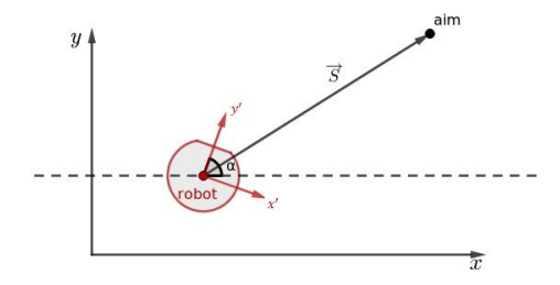
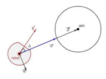
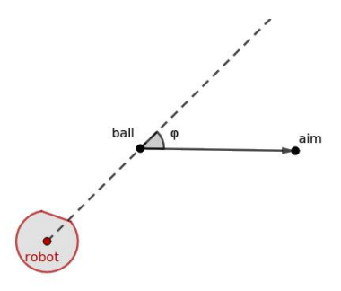
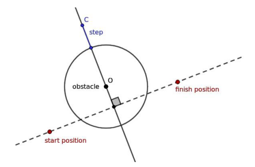
TakeAim: This function drives robot to the line, which connects ball and aim. This function controls, that robot stops at the desired distance from the ball on this line.
Input: robot position, aim coordinates, and parameters for function GoAroundPoint.
Output: robot velocity, angular robot speed.
4.4 Behaviour models
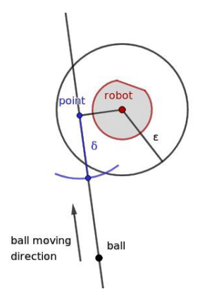
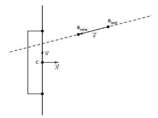
Goalkeeper: This function describes goalkeeper behaviour. Goalkeeper is moving along the goal and its trajectory is a line. If estimated trajectory of the ball is crossing the goal, robot is moving to the point of their intersection. Estimated trajectory is a line calculated from previous ball positions.
Input: robot position, ball position, goal center, goal vector $\overrightarrow{N}$.
Output: robot velocity.
To calculate intersection point of goals and ball trajectory we use the next formula:
$$t = \frac{\overrightarrow{CB}_{new} \wedge \overrightarrow{u}}{\overrightarrow{\delta} \wedge \overrightarrow{u}}$$
$$point = B_{new} + t \cdot \overrightarrow{\delta}$$
where ∧ – pseudo-scalar product.
To move to the point of intersection we use function MoveToPoint with PD-controller. In case of axe which is perpendicular to the goal, the speed is the most important thing, in case of parallel axe stabilization of robot is necessary. Therefore robot velocity along axes X and Y in global coordinates is calculated in different ways with different P and D coefficients. After this step velocities are transformed to robot coordinate system and summarized.
5 Acknowledgements
We wish to express our deep gratitude to prof. Alexey Matveev (SPbU) for his review and useful advice for the scientific sections of this paper. We also would like to thank Iakov Kirilenko (SPbU) for his enthusiastic encouragement and professional support. Special thanks should be given to previous research group (circa 2012-2016), which developed Robocup-SSL game for two-wheeled robots based on Lego, Arduino, and TRIK – Ilya Shirokolobov, Ruslan Sevostyanov, Kirill Ovchinnikov – for their responsiveness and advertency.
Our grateful thanks are also extended to JetBrains Research, which encourages leading students from our team with a scholarship. Finally, we wish to thank Presidental Lyceum of physics and mathematics 239 and CybetTech Labs Co Ltd for their valuable technical support on this project.
References
- Cybernetic constructor TRIK, official webpage, https://trikset.com official English webpage, http://blog.trikset.com/p/eng.html
- Russian inter-university robotics school, official webpage, https://vk.com/roboschool_vlg
- Robofinist, official webpage, https://robofinist.org
- Qt, official webpage, https://www.qt.io
- MATLAB, official webpage, https://www.mathworks.com/products/matlab.html
- Centralized control tool repository, https://github.com/robocup-ssl-russia/LARCmaCS
- SSL Vision system, official repository, https://github.com/RoboCup-SSL/ssl-vision
- Matlab algorithm library repository, https://github.com/robocup-ssl-russia/MLscripts
- Google Protocol Buffers, official webpage, https://developers.google.com/protocol-buffers
- Matlab C++ Engine API, official webpage, https://www.mathworks.com/help/matlab/matlab_external/engine-c-api-1.html
- Official SSL Vision standard pattern, http://wiki.robocup.org/images/9/96/Small_Size_League_-_Standard_Pattern_2011.pdf
- Microsoft Visual C++ compiler, official webpage, https://visualstudio.microsoft.com/ru/vs/features/cplusplus
- MinGW compiler, official webpage, http://www.mingw.org
- Travis CI, official webpage, https://travis-ci.com
- Static code analyzer Vera++, official webpage, https://bitbucket.org/verateam/vera/wiki/Home
- Matlab runtime compiler, official web page, https://www.mathworks.com/products/compiler/matlab-runtime.html
- Electrical and mechanical components https://github.com/robocup-ssl-russia/schemes