Description of the Warthog Robotics SSL 2019 Project
Rafael G. Lang, Guilherme C. de Oliveira, Heloisa J. Barbosa, Adam H. M. Pinto, Nicolás dos S. Rosa, Anderson H. de Siqueira, Ivan N. da Silva, Roseli A. F. Romero
Warthog Robotics University of São Paulo at São Carlos
Abstract This paper presents the Warthog Robotics Magic project, developed since 2011 at the University of São Paulo at São Carlos, and the main improvements made to the RoboCup SSL project since the last competition. The team is the current Latin American champion and under active development by the Warthog Robotics group. The mechanical structure is a mixed design using aluminum and composite materials and contains four DC motors for locomotion. The system architecture is based on the GEARSystem library, with a decision tree strategy module, and powered by some filtering algorithms on the vision module. During the last development cycle a new navigation technique and a filtering system were developed and incorporated to the project. The team presents full game capability with accurate and fast responses to strategy and referee commands.
Introduction
The Warthog Robotics group was created in 2011 by the fusion of the groups GEAR, founded in 2003, and USPDroids, founded in 2005, and now aggregates the knowledge of the departments of Electrical Engineering of the São Carlos School of Engineering, the Computer Sciences of the Institute of Mathematics and Computer Science, and the Center for Robotics of the University of São Paulo at São Carlos. The group counts with over 100 members from several knowledge areas, such as Computer Science and Electrical, Mechatronic and Computer Engineering, and develops robotics technologies in various areas, applying most of them at Robotics competitions. Due to budget limitations, the team was not able to participate in the last edition of the RoboCup. Despite the hiatus in international competitions, the last results in the Latin America RoboCup Open include the 2016 and 2018 first places and the 2017 second place.
Mechanical Structure
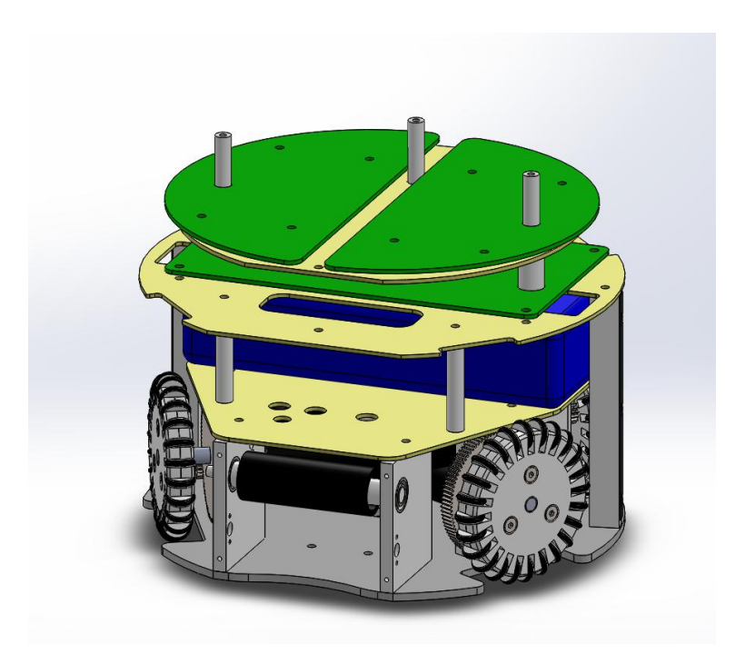
The mechanical structure is exactly the same one from the last years, composed of a locomotion system with four Faulhaber 2342 DC motors, a kicking device, and a dribble device mounted with shock absorber system. The upper part houses the three electronic boards, the battery and the kick capacitor using fiberglass plates; and the cover is a front cut cylinder with protected wheels and openings for the kicking and dribble devices. All mechanical structure is made of aluminum (gray parts) and composite materials (yellow parts) as shown in figure 1.
Electronic Devices
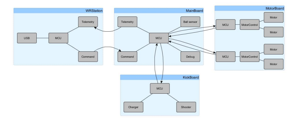
The electronic devices are the same of last years, composed of three electronic boards: MainBoard, MotorBoard and KickBoard and detailed information can be found in references 1, 2 and 3. The architecture of the embedded electronics is shown in figure 2.
Computer Systems
The WR Magic Project software is based on five sub-projects developed by the group: the GEARSystem library, the WRBackbone server application, the redesigned WRCoach strategy application, the WREye vision filtering application, and the WRStation radio communication application.
GEARSystem
To provide communication and distributed execution between system modules it is used the GEARSystem distributed library [10]. It is built over CORBA and is the same as used last years with minimal bugs extraction and improvements. This architecture allows the easy development of new software based on these main modules, and detailed information can be found in references 1 and 2.
In the current implementation of the team, the Sensor module is the WREye, responsible for receiving the data from ssl-vision and inserting it on the system. This module is composed by filters (Kalman, Noise, Loss and Multi Object) and more detailed explanation can be found in reference 2. The Server module is WRBackbone, connection all modules on the GEARSystem architecture. The Actuator module in the WRStation, sending commands via USB (using QtSerialPort [13]) to a custom station board that reproduces the commands wireless.
The commands sent by WRStation is generated by WRCoach, the Controller module on GEARSystem architecture and one of the most improved modules, since it contains the team's strategy.
WRCoach
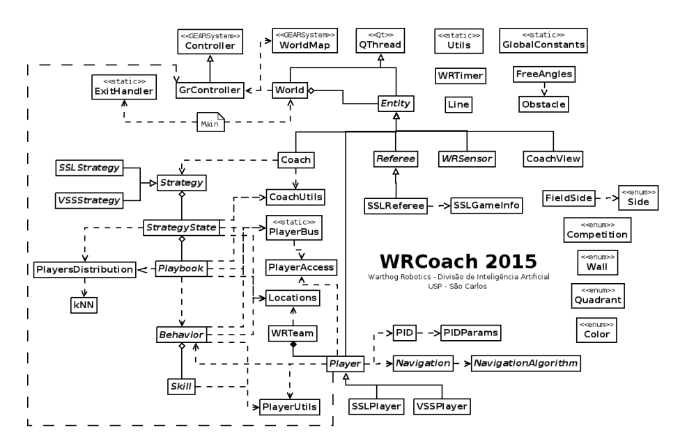
The coach responsible for setting the strategy to the team: Understand the world model, navigation, obstacle avoidance and behavior selection. A simplified diagram of the software architecture is presented in figure 3. The subsequent paragraphs describe the Coach architecture; a full description of the software is available in reference 2 and in Brazilian Portuguese at reference 12.
Improvements for 2019
As WRCoach is software that has been improved since 2016, its current version is pretty stable, but it always requires optimization and bug fixes. In reference 3 it was presented two main corrections: NaN (not a number) removal and the attacker behavior.
The NaN bug occurred because the WRCoach's final output is a float that represents speed in x,y and theta axis and some mistakes, as division by zero, resulted in a not a number being send to software or propagated to robot firmware. The routine added solved this problem.
The new complex attack behavior select the best time to shoot or pass the ball, choosing which has a clear path to goal or an free attacker in condition to trap the ball. This behavior improved the chances of goal of the team, avoiding some kicks that would be easily blocked by the rival team.
With the evolution of the attacker, the focus of improvement this year was on defense. Dynamic marking situations were added to the decision tree, where defenders positioned themselves to prevent kicking and clear passes. This behavior is even more important in cases where you play with a smaller number of robots. With a robot is kicked out, or even in maintenance during the game, the team needs to adapt to a more defensive condition in order to avoid the opposing goal. The goalkeeper's algorithms were also improved considering this dynamic marking. The goalkeeper needs to be more precise in recognizing the attacker's orientation, and act quickly to block the goal.
Some other skills have been added and are being tested, such as new indirect kick routines considering opponents robots (including the goalkeeper) and new studies for positioning players who are not directly participating in a current play. With this, robots need to consider, in addition to the free angles, better positioning within the quadrants, making better use of available space in the field.
The mechanical and electronic projects are the same from 2015 and are considered stable. The improvements in the embedded software (telemetry system) are still in beta version, but the faithful model of robot made possible research about quantity and quality of controllers applied, in a paper available only in Brazilian Portuguese Language [11].
In the Software Project, we had improvements in the WRCoach structure and the WREye. WRCoach is now stable and the focus are in improvements in high-level strategy. The best testing platform is the competition itself, but it is believed that software improvements have made the robot more competitive considering the games at the Latin American Open. In the next sessions, it is presented the new path planning strategy, using Univector Field-based Algorithm and a Kalman Filter.
Univector field-based algorithm
The Univector-based Field Navigation was proposed in reference 16 and is consists in a combination of two main potential fields: a move-to-goal univector field, and a avoid-obstacle univector field. The first one is by itself composed by two hyperbolic spiral univector fields, each one in a rotation direction (clockwise and counter clockwise).
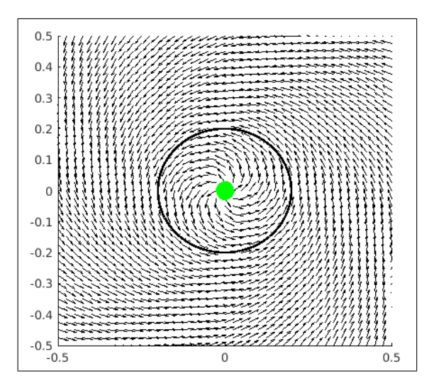
The Equation 1 defines the hyperbolic spiral, where p is the current position, θ is the angle from x-axis at the position p, K^r is the adjustable parameter, ρ is the distance between the origin and the position p, and d^e is the predefined radius that decides the size of the spiral. In the figure 4 it can be seen the parameters generated by our implementation. If K^r becomes larger, the spiral becomes smoother. The notation ± represents the direction of motion, where + means clockwise, and − means counter clockwise.
$$\phi_h(p, d_e) = \begin{cases} \theta \pm \frac{\pi}{2} \left(2 - \frac{d_e + K_r}{\rho + K_r}\right), & \text{if } \rho > d_e \ \theta \pm \frac{\pi}{2} \sqrt{\frac{\rho}{d_e}}, & \text{if } 0 \le \rho \le d_e \end{cases}$$ (1)
The move-to-goal univector field is a composition of two hyperbolic spiral univector fields, positioned to form a navigation field that can generate the direction vector to control the robot orientation when reaching the target position. The Equation 3 defines the velocity vector angle for a position, using the φ^h from Equation 1, where Nh(p, de) is defined in Equation 2, y^l and y^r are defined in Equation 4, and p^l and p^r are defined in Equation 5, with cw refering to clockwise, and ccw to counter clockwise.
$$N_h(p, d_e) = [\cos\phi_h, \sin\phi_h]^T \tag{2}$$
$$\phi_{TUF} = \begin{cases} \angle \frac{y_l N_{h(CCW)}(p_l, d_e) + y_r N_{h(CW)}(p_r, d_e)}{2d_e} & \text{if } -d_e \le y < d_e \ \phi_{h(CW)}(p_l, d_e) & \text{if } y < -d_e \ \phi_{h(CCW)}(p_r, d_e) & \text{if } y \ge d_e \end{cases}$$ (3)
$$y_l = y + d_e , y_r = y - d_e$$ (4)
$$p_l = [x, y - d_e]^T, \quad p_r = [x, y + d_e]^T$$ (5)
The avoid-obstacle univector field is the same as the classical potential field method, with the exception that there isn't decay with the distance because all the vectors are unitary. We can define it as in Equation 6, without the implementation of the virtual obstacle position described in reference 16.
$$\phi_{AUF} = \angle (p - p_{obst}) \tag{6}$$
To compose the move-to-goal (φ_{TUF}) with the avoid-obstacle univector field (φ_{AUF}) a Gaussian function, defined in Equation 7, is used as a compound ratio in the composition process along with the distance between a robot and a obstacle, where dmin defines a minimum distance in which the move-to-goal univector field can be applied. The avoid-obstacle univector field is solely applied if the distance is less than dmin from the center of the repulsive obstacle, and the composition is applied outside the distance dmin.
$$G(r,\delta) = e^{-\frac{r^2}{2\delta^2}} \tag{7}$$
$$\phi = \begin{cases} \phi_{AUF}, & \text{if } R \leq d_{min} \ \phi_{AUF}G(R - d_{min}, \delta) + \ +\phi_{TUF}(1 - G(R - d_{min}, \delta)), & \text{if } R > d_{min} \end{cases}$$ (8)
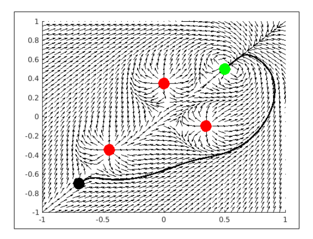
Using our implementation, the Figure 5 shows the results of the composed univector field with path generation for direction vector of 3π/2 with three point obstacles.
Kalman Filter
Kalman filter is a continuous cycle of predict-update used in WREye to ball and robots position prediction. The following equations form the main loop of the filter:
$$X_{t,t-1} = \Phi X_{t-1,t-1} \tag{9}$$
$$S_{t,t-1} = \Phi S_{t-1,t-1} \Phi^T + Q \tag{10}$$
$$K_t = S_{t,t-1}M^T[MS_{t,t-1}M^T + R]^{-1} \tag{11}$$
$$X_{t,t} = X_{t,t-1} + K_t(Y_t - MX_{t,t-1}) \tag{12}$$
$$S_{t,t} = [I - K_t M] S_{t,t-1} \tag{13}$$
The output from the filter is the result of the state update (Equation 12) and state covariance update equations (Equation 13). These provide the combined estimate from the model (prediction equations) and latest observation (measurements). The state matrix provides the mean value of the distribution for each state variable, and the covariance matrix provides the variances.
In calculating the gain and update, it ix helpful to break the calculations in the following meaningful manner. First, it is calculated the "innovation", which is the difference between the new data and the previous prediction.
$$J = Y_t - MX_{t,t-1} \tag{14}$$
Then calculate the covariance of the innovation. The Equation 16 and Equation 17 calculates the gain matrix and the updated state.
$$COV(J) = MS_{t,t-1}M^T + R \tag{15}$$
$$K_t = S_{t,t-1} M^T \operatorname{COV}(J)^{-1} \tag{16}$$
$$X_{t,t} = X_{t,t-1} + K_t J \tag{17}$$
Conclusion and Future Work
In computer system, the improvement of the coach described in references 2 and 3 was a great change in the strategy of the WRCoach and turn it more complex. The algorithm are more stable and efficient, with the cost of the defeat in 2017 and non-participation in the world cup in 2018, but now the robot is really competitive.
The developed hardware is robust, reliable and provides an excellent platform to the strategy systems, and the improvements were focused in the embedded software as show in this paper, like the controller of the robot.
Future works will be focused mainly in those areas, improving the software WRCoach and the embedded software of the robot like the controller.
Acknowledgments
The authors would like to thank all Warthog Robotics team for the help and friendship; the University of São Paulo for the facilities and financial support; the Embraer, OSG Sulamericana, Griffus and SolidWorks companies for the technical sponsorship; and all others that helped us during the project.
References
- Lang, R.G., Bernardo, A.M., Oliveira, G.C., Menezes, H.B.B., Ramos, L.C., Roque, L.G.S., Silva, I.N., Romero, R.A.F.: Description of the Warthog Robotics 2015 project. In: 2015 RoboCup (2015)
- Lang, R.G., Oliveira, G.C., Menezes, H.B.B., Rosa, N.S., Correa, R.A., Gomes, V.H., Silva, I.N., Romero, R.A.F.: Description of the Warthog Robotics 2016 project. In: 2016 RoboCup (2016)
- Lang, R.G., Oliveira, G.C., Barbosa, H.J., Rosa, N.S., Cepeda, B.H., Siqueira, A.H., Silva, I.N., Romero, R.A.F.: Description of the Warthog Robotics 2017 project. In: 2017 RoboCup (2017)
- Nordic Semiconductor: High Frequency 2.4 GHZ Wireless Transnciever. Data Sheet (2007)
- Olivera, V.A., Aguiar, M.L., Vargas, J.B.: Sistemas de Controle Aulas de Laborat´orio. EESC-USP, Brasil. (2005)
- Aguiar, M.L.: SEL359 Controle Digital,2015. EESC-USP, Brasil. (2015)
- Pressman, A.I.: Switching Power Supply Design. McGraw-Hill. (2003)
- Mohan, N., Undeland, T.M., Robbins, W.P.: Power Electronics Convertes Application and Design. Wiley (2002)
- Tse, C.K.: Complex Behavior of Switching Power Converter. CRC Press. (2003)
- Lang, R.G., Romero, R.A.F., Silva, I.N.: Development of a Distributed Control System Architecture. In: 2014 Latin American Robotics Symposium. (2014)
- Furlan, M. S., Silva, I.N.: Comparação de Controladores PID em Sistema de Malha Dupla em Robôs Omnidirecionais. In: 2018 Simpósio Internacional de Iniciação Científica da Universidade de São Paulo. (2018)
- WRCoach v2 documentation. Division of Artificial Intelligence - Warthog Robotics, available at https://www.assembla.com/spaces/warthog-dia/wiki/WRCoach_v2.
- Qt Company: QSerialPort documentation, available at http://doc.qt.io/qt-5/qtserialport-index.html.
- Wikipedia: PID Controller, available at https://en.wikipedia.org/wiki/PID_controller.
- Control System Labs: Discrete-time PID Controller Implementation, available at http://controlsystemslab.com/discrete-time-pid-controller-implementation/
- Y. Lim, S. Choi, J. Kim, and D. Kim, "Evolutionary Univector Field-based Navigation with Collision Avoidance for Mobile Robot", The International Federation of Automatic Control, vol. 17, pp. 12787-12792, 2008.