KgpKubs 2020 Team Description Paper
Manjunath Bhat, Snehal Reddy, Shamin Aggarwal, Aniruddha Kirtania, Abhinav Gupta, Chitrang Garg, Anirudh Roy, Gopi Reddy Chilukuri, Murali Karthik, Aditya Agrawal, Debajit Chakraborty, Sahil Jindal, Parth Mall, Hardik Aggarwal, Sharat Bhat, Kushal Kedia, Ayush Shishir Jodh, Ayan Chakraborty, Gauri Wadhwa, Utkarsh Agrawal, Moinak Ghosh, Saikat Mandol, Shivanshu Singh, Taban Salam, Mayank Bhushan, Saurabh Agarwal, Sayan Sinha, Sudarshan Sharma, Tanishq Jasoria, Ankush Roy, Shivam Kumar Panda, Alok Kanti Deb, Jayanta Mukhopadhyay
Indian Institute of Technology, Kharagpur West Bengal, India
Abstract This paper describes the mechanical, electronic and software designs developed by Kharagpur RoboSoccer Students' Group (KRSSG) team to compete in RoboCup 2020. All designs are in agreement with the rules and regulations of Small Size League 2020. Software Architecture implemented over Robot Operating System(ROS), trajectory planning and velocity profiling, dribbler/kicker design and embedded circuits over the last year have been listed. Our website: krssg.in
1 Introduction
KgpKubs is a RoboSoccer team from the Indian Institute of Technology Kharagpur, India. The research group aims to make autonomous soccer-playing robots and participate and conduct various related events. Undergraduate students from varied departments and years are a part of this group. We have previously participated in FIRA RoboWorld Cup in the years 2013-2015 in the Mirosot League and secured the Bronze Medal in the same in 2015. We have also participated in RoboCup SSL & 3D-Simulation League in Nagoya, Japan 2017. In June 2018 we participated in RoboCup 3D-Simulation League in Canada.
This paper is a continuation of last year's Team Description paper and describes the developments made since the last year. Mechanical design of the robots is presented in section 2. The firmware and embedded circuits are described in section 3, followed by the software system in section 4. Finally, discussions and future work are described in section 5.
2 Mechanical Design
Mechanical parts and assemblies were designed in SolidWorksR. Most of the static simulations were run extensively using AnsysR (Workbench) to aid the process of material selection. The behaviour of different mechanical parts under dynamic loading and simulations related to optimisation of kicking velocity and height were realised using MATLABR Simscape Multibody.
The previous robot chassis was manufactured completely using Aluminium 6061, which added to its cost and weight. This year most of the parts have been built using 3D printing with PLA/ABS. All the electrical components have been housed in an insulated compartment, which ensures safety and accessibility inside the robot. Table 1 summarizes the hardware configuration of the bot.
Table 1: Robot Hardware
| Dimensions | Dia: 179mm , Height: 149mm |
|---|---|
| Driving motors | Maxon EC-45 Flat (50W) |
| Gear Type | Internal Spur |
| Gear Ratio | 1:3.3 |
| Wheel diameter | 50mm |
| Dribbling motor | Maxon EC-16 (30W) |
| Dribbling gear Ratio | 9:11 |
| Dribbling bar diameter Dia: 10mm | |
| Max. ball coverage | 19% |
| Sub-wheel Diameter | 10mm |
2.1 Dribbler
The old design of dribbler grip, as mentioned in the KgpKubs TDP 2019[1] was feasible for low angular acceleration of the bot. However, high acceleration and jerky motion experienced during the initial locomotion tests of the bot make the older design impractical in actual implementation. Moreover, the hard silicone grip used earlier did not provide much damping, which resulted in a jerky motion of the ball, especially during dribbling at high speeds.
This year, KgpKubs shall be playing with a new dribbler grip capable of selfcentring the ball at considerably high angular accelerations and with a better ball catching and holding skill owing to its damping material. To accomplish this, the diameter of the dribbler rod was reduced considerably by 4mm to accommodate a grip with a relatively larger thickness.
The design of the dribbler grip consists of two main features:-
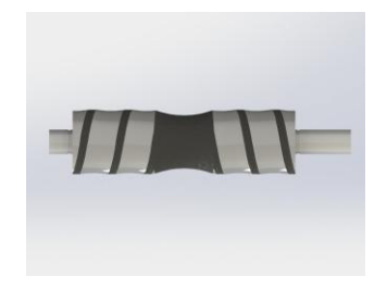
- Self-centering: Left and right helices were designed on the outer periphery of each side of the grip to self-centre the ball dynamically during the match. Inspiration was taken from the rack and pinion mechanism in which pinion rotates, and rack translates backwards or forward depending upon the direction of rotation of the pinion. The helices have a pitch, which is reducing continuously to help in centring the ball quickly and effectively.This feature has been added by referring to Evolution of dribbling mechanisms in Robo 2. Concavity: A concavity with the radius of curvature nearly equal to the radius of the ball was introduced in the middle of the grip and in between the helices to hold and stabilise the ball near the centre of the grip.
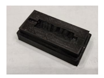
All the calculations related to design and optimisation were done in MATLABR. Dribbler grip was made by the liquid silicone moulding process using Smooth On Inc. EcoflexTM00-50 soft silicone of the dribbler rod was reduced considerably by 4mm to accommodate a grip with a relatively larger thickness. As shown in fig 1(a), two mould boxes having the corresponding internal cavities in the shape of helices are designed and 3D printed using PLA material. Liquid Silicone Rubber(LSR) at a suitable temperature was poured from the top and allowed to cool down to give the final shape to the dribbler grip. This method offers greater control over the hardness of the grip by varying the pouring temperature, cooling rate and dramatically reduces the cost of manufacturing as well. The latest model of the dribbler grip, as shown in fig 1(b) was tested multiple times and yielded satisfactory results during the locomotion of the bot.
2.2 Kicking Mechanism
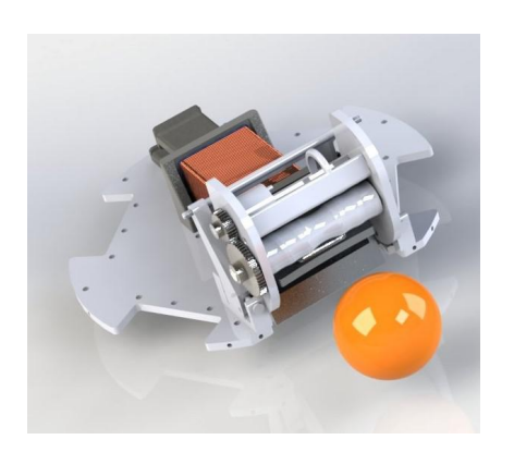
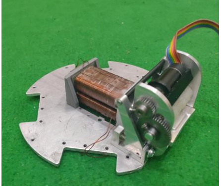
The straight kicker is powered by two 250V 2200uF capacitors, which can be charged by a step-up converter to 200V each. A prototype of the dual kicking system, as described in the KGPKubs TDP 2019[1] has been installed in the bot. The support system to solenoids is 3D printed of ABS plastic, as shown in fig 2. Plastic is preferred over 6061-Aluminium alloy to avoid additional weight to the bots and for the ease of manufacturing at low cost. The new anodised plunger and a 3D printed solenoid would prevent any short-circuiting problems, which was the issue of primary concern. However, this increases the chances for shorter durability due to the repetitive impact of plungers. Hence, damping pads are introduced at the major areas of impact along with ribs in the support to withstand high compressive stress. In order to accurately time the kick, IR sensors have been mounted beside the dribbler for ball detection.
After optimising the space for two rectangular solenoids for straight and chip kicker respectively in place of a single cylindrical solenoid as mentioned in KGPKubs TDP 2018[4], initial tests on the prototype had shown that the kicking speed has still reduced significantly compared to before. This issue with the kicking speed is more prominent in the case of chip kicking, restraining the bot from hitting the ball to the expected range. The primary cause of slow kicking is a relatively lesser number of windings available per solenoid due to dimensional constraints. The winding is currently done using 23AWG copper wire. Solenoid Specimens with minor dimensional changes are being tested with 24AWG, 25AWG, and 26AWG copper wires to get the best possible kicking speed, which will be used in RoboCup 2020.
3 Embedded Systems
3.1 Main controller board
Xilinx Spartan 6 is used as the central processing unit which controls four base motors, dribbler and other peripherals. The communication between the mainboard and the central server is established using Nordic Semiconductors' nRF52840 modules. For accurate kicking, IR obstacle sensor module has been used to sense the appropriate location of the ball before kicking. Lithium Polymer (Li-Po) over-discharge protection circuit is incorporated in the main circuit.
3.2 Motor Controllers
Earlier the motor drivers had been designed using IR4427, IRF7389 and PID control logic through FPGA. These driver circuits were based on 3 phase DC-AC inverter topology where the FPGA provides the necessary gate pulses through Trapezoidal commutation scheme. IR4427 is used as the gate driver in these motor driver circuits. It is a low voltage, high-speed power MOSFET and IGBT driver. The output drivers feature a high pulse current buffer stage designed for minimum driver cross-conduction. IRF7389 is an Ultra Low-On resistance MOS-FET IC. The MOSFET gate resistors were chosen so as to match propagation delays between the N- channel and P- channel for optimal switching losses. The filtering capacitors were also chosen accordingly so as to reduce high-frequency components considerably. Even though the passive components were optimised to their maximum extent with considerable changes in the PCB layout, the final driver circuit wasn't robust enough for a power-efficient dynamic gameplay. This leads us to search for sophisticated monolithic BLDC Controllers for better efficiency.
This year, the team shifted to MC33035 and its companion IC MC33039. The MC33035 is a high-performance second generation monolithic brushless DC motor controller containing all of the active functions required to implement a full-featured open loop, three or four-phase motor control system. This device consists of a rotor position decoder for proper commutation sequencing; temperature compensated reference capable of supplying sensor power, frequency programmable sawtooth oscillator, three open collector top drivers, and three high current totem pole bottom drivers ideally suited for driving power MOSFETs. Also included are protective features consisting of under-voltage lockout, cyclebycycle current limiting with a choice for time-delayed latched shutdown mode, internal thermal shutdown, and a unique fault output that can be interfaced into microprocessor-controlled systems. The MC33039 is a high-performance closedloop speed control adapter specially designed for use in brushless DC motor control systems. Implementation will allow precise speed regulation without the need for a magnetic or optical tachometer.
The MC33035 and MC33039 have been successfully implemented and tested with the current motors. Improvements include lower current usage, better transient response during dynamic conditions and considerably lower noise. The protection circuits inside the MC33035 will protect the circuit from damage in case of malfunction.
3.3 Communication Module
Till last year ESP32 WiFi module by Microchip was used as a mean of communication. But we faced a lot of problems due to the protocol used 802.11 n uses the 2.4GHz ISM band because of this choice of band equipment suffers interference from microwave ovens, cordless telephones, and Bluetooth devices leading to data loss which causes a lot of trouble. Hence we decided to discard the module for communication purposes.
This year we decided to use nRF52840 from Nordic Semiconductors. nRf52840 is an advanced low power system on chip (SoC) that provides Bluetooth, ANT, 802.14.5 and proprietary RF capabilities. At its core, we have an Arm Cortex-M4 processor allowing quicker and more efficient computation of complex functions. It is integrated with automated peripheral power management, fast wake-up using 64 MHz internal oscillators, easy DMA automated data transfer between memory and peripherals, quadrature decoder.
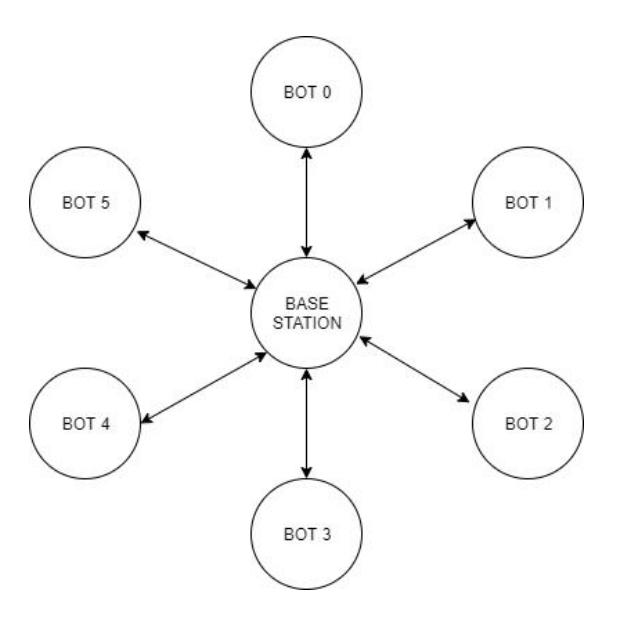
The air data rate of nRF52840 is nearly 2Mbps which provides us with bidirectional data transfer and providing a link between our bots and our server. We are using the Enhanced ShockBurst (ESB) protocol for communication which can be used at air data rates of 1Mbps and 2Mbps. A base station consisting of one nRF will be connected to the PC which receives data from the PC, acting as a central server(Fig: 3). The received data is then sent to the nRFs connected on the bot by the ESB protocol which uses the proprietary RF capabilities of the nRFs
3.4 Kicking Mechanism
Variable kicking speeds were achieved by enabling the trigger for different time periods using the FPGA hence discharging the capacitor to different voltages. Earlier, the bot was only able to kick the ball at maximum speed which made it difficult for the bot receiving the pass to position itself. Our testing showed that with this addition, kicking the ball to a specific position on the field became more precise.
3.5 Fault Diagnosis Circuit
Previously, ACS712 were used to determine the current drawn by bot during dynamic gameplay. ACS712 is a fully integrated, hall effect-based linear current sensor with voltage isolation and is a low resistance current conductor. In the present model, the team has integrated ACS712, MAX942, and Monostable multivibrator to detect the current impulse and short circuit current flowing to the bot. In this design, the current impulse and short circuit current flowing to a bot can be distinguished separately and thereby, appropriate action can be taken accordingly. In the case of a current impulse, the functioning of bot stops for a short interval whereas, in the case of a continuous short circuit, the bot shuts down.
3.6 Advanced Control Algorithms
DC motors, in general, do not have a linear rpm-PWM relationship. In a dynamic environment such as RoboCup, the external environment influences the working of the motor, and the motor may require different PWM values to reach the target. An automated non-linear correction function is essential to provide outputs in arbitrary conditions. PID control logic is the most popular control system but tuning its parameters is time-consuming. A PD controller with fuzzy logic was developed to bypass the tuning process and automatically optimise the parameters on an STM Microcontroller to be ported later to the FPGA. The various process used are described briefly below:
- The fuzzy controller takes the error and change in error as input and outputs Kp and Kd parameters.
- Fuzzification: PE, ZE, NE, PDE, NDE and ZDE were initialised to zero. The values were updated according to the input membership functions above.
- Creating the Fuzzy Matrix ( Rule Base ): 3x3 matrix used: For simplification, a 3x3 Rule Base Matrix was implemented for the Kp Controller and Kd Controller.
- Defuzzification: The Defuzzification function is responsible for computing the crisp values of Kp and Kd from the created fuzzy matrix.
- These new values are fed into a PD function. Finally, the resultant PWM is calculated.
4 Software
The following section has the description of the developments and changes made on the software side, since our last participation in SSL. Section 4.1 describes the structure of the roles added this year and the changes in basic behaviors, Section 4.2 describes the integration of Kalman Filter in our codebase, Section 4.3 discusses the integration of SSL game controller, Section 4.4 highlights a deep learning-based approach to pilot the RRT* sampling algorithm towards the destination and away from the obstacles using the concept of artificial potential field.
The FSM structure of codebase is based on Harel State Machines [7], making use of hierarchy, parallelism and broadcasting. Each state of the state machine is a part of its parent state, forming a hierarchical model. We use parallel processing to run referee server along with the belief state server (the server of the state containing the current properties such as position and velocities of the bots and the ball). This ensures that the data is broadcast simultaneously from one state to another.
4.1 Roles
This section describes the improvement in GoToBall and the FSM architecture of roles added to the play which are assigned by the Role Assignment Module as described in KgpKubs TDP 2019[1].
GoToBall: GoToBall is one of the most fundamental functionalities in RoboSoccer. Attacking, defending and other roles depend on it. The previous Go-ToBall architecture used a coarse approach to get to the ball without aligning towards a particular angle and then used a fine-tuning method to align itself with the ball once it reached the ball. Time is wasted in fine-tuning method, which is now resolved by rotating while moving. This improved KickToPoint as well, which depends on GoToBall. GoToBall is now improved to align while it moves towards the ball and achieved significant improvement in the Attacker sub-behavior, leading to smoother kicking and passing.
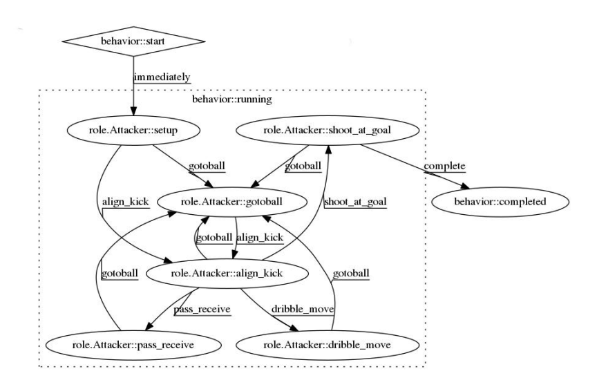
The Role Assignment Module is used for automatic allocation of tasks to the bots which have completed or failed their previous assigned role in a dynamic soccer game environment. We have a fixed set of tasks, and each of them is related to a particular situation based on the positions of agents and the ball on the field. Using the current game state, we then assign each bot a task. An overall architecture is implemented to coordinate the various sub-behaviors of defender, attackers and midfielders. Various roles added to the play are described below:
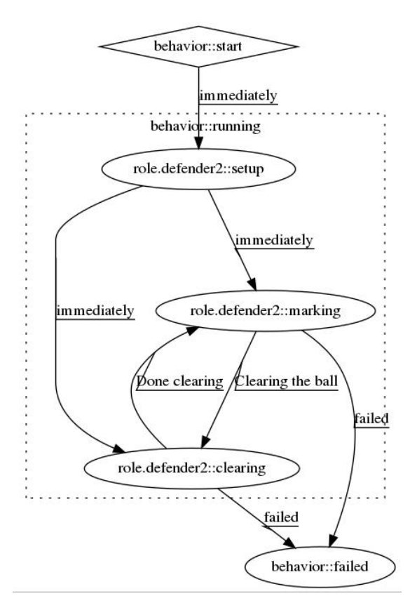
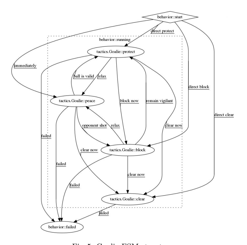
Co-ordinated Defense Play: For the defensive sub-behavior, roles are dynamically assigned to each of the robots of two defenders and a goalkeeper. The defenders protect the ball within a specified threshold and clear the ball. The goalkeeper has two main behaviors of following the ball subject to various conditions, and it clears the ball for safe conditions.
4.2 Kalman Filter
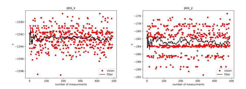
The input data received from the camera, irrespective of the quality of the device, is always noisy. Even if the deviation from ground truth is rare, it can cause problems in velocity calculations. In real-time, even small deviations from real values can result in wrong commands being sent to the robots, compounded by over-correction, resulting in failure of roles. Earlier, we were using the Savitzky Golay filter [10]. This time we have successfully implemented the Kalman filter [11] on the data received from the vision. The difference between them is that the former helps in reducing the noise, whereas the latter sees through the noise.
The main use of the Kalman filter is for velocity calculations. The velocity of the ball is a critical piece of information because it helps in predicting the position of the ball, which is important for the interception of the ball. Earlier, the velocity was calculated in a naive manner:
$$velocity = \frac{x(t) - x(t - \Delta t)}{\Delta t}$$
where x(t) and x(t − ∆t) are the positions of bot at timestamp t and (t − ∆t) respectively.
Due to noise in the received data, even if the ball is lying at rest at some point (x, y), we get its position in the range (x±∆x, y ±∆y) (Fig. 7). This leads to unwanted velocity results. Using the Kalman filter, these unwanted velocities are not considered.
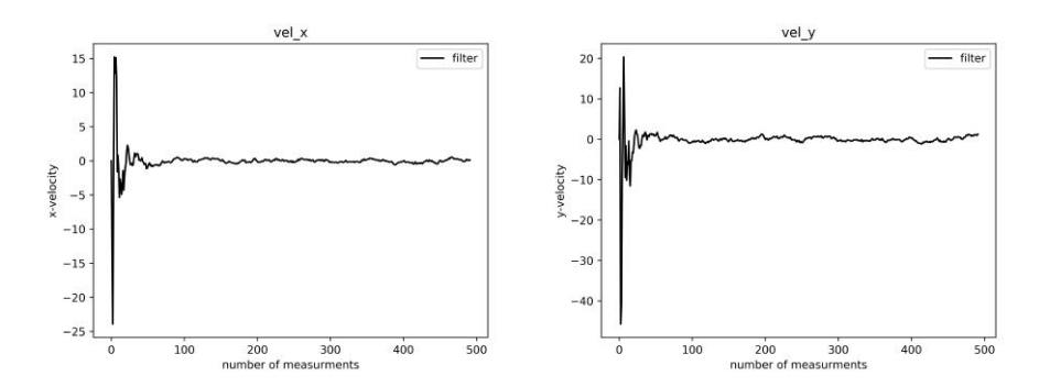
The Kalman filter was implemented independent of our codebase, and then the constants were tuned to get the best results. This was done in Python with the help of the NumPy library. Then the filter was applied to the vision data. This was done in C++ using the Eigen library. Initially, the filter was applied on the data received from grSim (a RoboSoccer simulator), which gives us the actual values of the position of the ball and the bots. The filtered velocities are shown in Fig. 8.
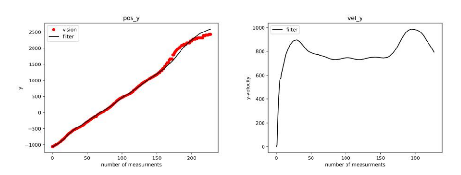
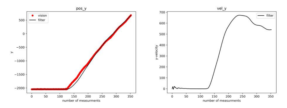
This was done to find the constants which converge to the values in the least number of frames. Then the filter was implemented on data from the camera (Fig. 9, 10). The received input contains high amount of noise. As stated earlier, such a noisy input completely ruins the velocity calculations. The Kalman filter converged to the actual values quickly.
4.3 SSL Game Controller
The SSL Game Controller replaces the SSL-refbox. With the introduction of automatic referees, there was a demand for several new features. To accommodate these, the SSL-refbox has been rewritten to take advantage of modern technologies.
The referee messages sent by the UI are received by our system clients. The various clients are:
- ssl-ref-client: A client that receives referee messages
- ssl-auto-ref-client: A client that connects to the controller as an autoRef
- ssl-team-client: A client that connects to the controller as a team
A list of features added are:
- Modern, scalable Web-UI
- More control of the state (change almost all values)
- Automatically save and restore state
- State history with undo button
- Game Log that documents commands and events
- New interfaces for autoRefs and teams
- A graphical client can be integrated
The clients use the information to broadcast the messages on the rostopic. An additional state is assigned to each skill which checks for an incoming message from the /ref data topic while transitioning from one state to another. Parallel processing is used to run the referee server alongside the main belief state server. This ensures that the referee messages can be accessed at any time during the execution of a play. When a message to halt the game is received, the plays transition to the ref state which uses multiprocessing to place the bots as per the referee message. The play is resumed from that state when a message to resume is received. The GoToBall FSM is changed accordingly.
4.4 Deep Learning rooted Potential Piloted RRT* for expeditious path planning
Randomised sampling-based algorithms such as RRT* have widespread use in path planning, but they tend to take a considerable amount of time and space to converge towards the destination. RRT* with an artificial potential field (RRT*- APF [8]) is a novel solution to pilot the RRT* sampling towards the destination and away from the obstacles, thus leading to faster convergence. But the ideal potential function varies from one configuration space to another and different sections within a single configuration space as well. Finding the potential function for each section for every configuration space is a gruelling task. Deep Learning is pretty standard today to solve path planning based problems [9]. To solve this problem, in particular, we devised the DLP-RRT* algorithm[2]. The two-dimensional configuration space was divided into multiple regions and a deep learning-based approach, by using custom feed-forward networks to tune the sensitive parameters which determine the potential function. These parameters act as a heuristic and pilots the tree towards the destination, which has a substantial effect on both the rate of convergence and path length. DLP-RRT*, which is a novel algorithm developed by our group, has shown the ability to learn and emulate the shortest path that was generated by Dijkstra's algorithm and converges much faster than the current random sampling algorithms as well as deterministic path planning algorithms described in this paper [3]. This helps in dynamic RoboSoccer environments where path planning queries are frequent and require a quick generation of optimal paths. The following tables depict the performance of DLP-RRT* in comparison with RRT* and Dijkstra's algorithm in a given 2D configuration space.
Time of Convergence (in seconds)
| S.No. | RRT* | DL-P-RRT* | Dijkstra |
|---|---|---|---|
| 1 | 2.329800 | 0.986253 | 8.857095 |
| 2 | 1.998531 | 0.81104 | 9.103717 |
| 3 | 5.170486 | 0.978344 | 8.656968 |
| 4 | 2.336515 | 0.910896 | 8.927036 |
| 5 | 1.288411 | 0.238291 | 8.410355 |
Length of the final path
| S.No. | RRT* | DL-P-RRT* | Dijkstra |
|---|---|---|---|
| 1 | 2733.29 | 2267.12 | 2207.77 |
| 2 | 2639.58 | 2597.48 | 2518.91 |
| 3 | 2971.05 | 2256.47 | 2198.63 |
| 4 | 2662.99 | 2697.83 | 2620.49 |
| 5 | 2679.56 | 2125.55 | 2090.69 |
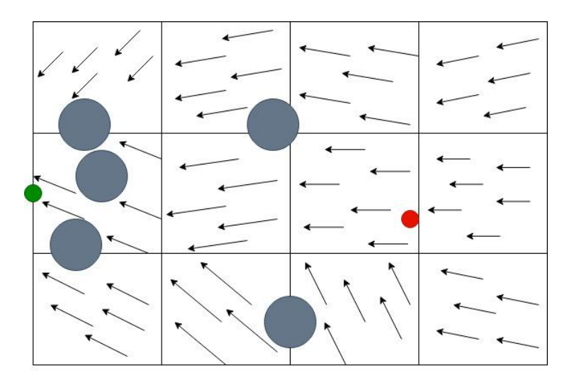
5 Discussion and Future Works
Modular Learning Strategies in Robot Soccer: Dividing possible sets of commands to send to robots into tasks or 'skills', which can collectively be used in higher layers like 'roles' can make it easier to quantify the complex environment around the robot. We aim to use a modular machine learning paradigm in which a complex 'behavior' is learned from a collection of simpler learned 'sub-behaviors' and so on. There have already been some promising publications on 'layered learning', we aim to study these, implement them if needed and improve on them.
Acknowledgements
The team also acknowledges the mentorship and guidance of our professors Prof. Jayanta Mukhopadhyay, Prof. Sudeshna Sarkar, Prof. Alok Kanti Deb and Prof. Dilip Kumar Pratihar. This research is supported by Sponsored Research and Industrial Consultancy (SRIC), IIT Kharagpur. We also thank our former team members who made all of this possible.
References
- KGPKubs Team Description Paper, RoboCup 2019 Symposium.
- Snehal Reddy Koukntla, Manjunath Bhat, Shamin Aggarwal, Rajat Kumar Jenamani, Jayanta Mukhopadhyay. Deep Learning rooted Potential piloted RRT* for expeditious Path Planning. 4th International Conference on Artificial Intelligence and Robotics, At Shenzhen, China.July 2019
- Peter Stone, Richard S.Sutton, Satinder P.Singh Reinforcement Learning for 3 vs. 2 Keepaway Robot Soccer World Cup (RoboCup)
- KGPKubs Team Description Paper, RoboCup 2018 Symposium.
- ESP32 Datasheet, July, 2018. https://www.espressif.com/sites/default/files/documentation/esp32_datasheet_en.pdf
- Spartan-6 FPGA Data Sheet. https://www.xilinx.com/support/documentation/data_sheets/ds162.pdf
- Harel D, Kugler H. Synthesizing state-based object systems from LSC specifications. International Journal of Foundations of Computer Science. 2002 Feb;13(01):5-1.
- Saurabh Agarwal, Ashish Kumar Gaurav, Mehul Nirala, Sayan Sinha. Potential and Sampling Based RRT Star for Real-Time Dynamic Motion Planning Accounting for Momentum in Cost Function, ICONIP 2018
- Sinha S, Nirala MK, Ghosh S, Ghosh SK. Hybrid path planner for efficient navigation in urban road networks through analysis of trajectory traces. In2018 24th International Conference on Pattern Recognition (ICPR) 2018 Aug 20 (pp. 3250- 3255). IEEE.
- Schafer, Ronald W. "What is a Savitzky-Golay filter?[lecture notes]." IEEE Signal processing magazine 28.4 (2011): 111-117.
- Welch, Greg, and Gary Bishop. "An introduction to the Kalman filter." (1995): 41-95.
- Steve Stancliff "Evolution of Active Dribbling Mechanismsin RoboCup", 16-741 Project, 2005 April 25
- Joydeep Biswas, Juan P. Mendoza, Danny Zhu, Benjamin Choi, Steven Klee, Manuela Veloso; Opponent-Driven Planning and Execution for Pass, Attack,and Defense in a Multi-Robot Soccer Team