MIT RoboTeam 2020 Team Description Paper
Jose Martinez De Leon, Michelle Tan, Joshua Piel, Hyeonji Oh, Ifeoluwapo Ademolu-Odeneye, Eyob Woldeghebriel, Rolando Gonzalez, Pedro Sales, Will Guter, Diane Heinle, Jonathan Samayoa, Marcus Badgett, Nathaniel Lee, Richard Liu, Rowan Cheung, Ian Perez, Aparna Gupte, Dylan Weber, Marisa Hoosen, Billal Iqbal, Naseem Hamad, Alisha Fong, Kevin Pho
Massachusetts Institute of Technology, Cambridge MA 02139, USA
Abstract This paper provides an explanation of the mechanical, electrical, and software designs of the MIT RoboTeam to compete in RoboCup 2020 in Bordeaux, France. Given that this is the first year the MIT RoboTeam is entering the soccer competition, much of our paper will focus on our initial approach and design process to solving the technical requirements presented by the competition.
Introduction
The MIT Robotics Team is a student-run group of highly motivated undergraduate students from the Massachusetts Institute of Technology. Our diverse group, with majors ranging from Mechanical Engineering to Physics and Aeronautics to Business, share a common passion for the field of robotics. The team's purpose is to explore exciting new technologies, learn critical skills, and promote the field of robotics through entering a variety of competitions and engaging in outreach events in the wider community. Unlike many other student teams, the Robotics Team is not formed around any one particular contest or event. Previously, our team participated in RoboCup Rescue 2017 and 2018. Rather, the team prefers to continually evolve through finding exciting new opportunities for a challenge where they can use the skills they have developed from previous experiences.
This year is our first year entering the RoboCup Soccer competition, and we have benefited from the ample open-source information from previous competitions. We began this project in August of 2019. RoboCup Soccer has had a very high barrier to entry so we will be entering the B league as this is more geared towards new teams. We hope entering the B league this year will be a stepping stone to entering the A league after more time and experience. RoboCup Soccer has been extremely enjoyable to get started on given the ample information available online and the open-source code-bases which gave us a jump start into the process. We were fortunate to receive advice from existing teams including Robojackets Georgia Tech and the Harvard Undergraduate Robotics Club as well as studied many of the ETDP and TDPs created by other teams.
In addition to having access to plenty of information provided by existing teams, we have a large team which enjoys the challenge of working on extremely short timescales. This gives us confidence that we are able to make efficient and quick progress leading up to the competition this summer, especially given the rate we have improved since we began this project five months ago. In the time left before the competition, we will be able to scale our system up past the one prototype robot that we have to a fully functioning team of six.
Mechanical
Our goal for the mechanical subsystem was to address all the absolutely necessary capabilities of a SSL robot. Through taking advantage of computational fabrication processes, we have been able to iteratively design our principal mechanisms, which include: the drivetrain, kicker, and dribbler. The design for all of these mechanisms have taken heavy inspiration from a study of standard mechanical designs across the SSL league. Since this is our first year competing in SSL, we decided that leveraging the experience of other teams in this competition was the best path to designing a successful system.
2.1 Drive Train
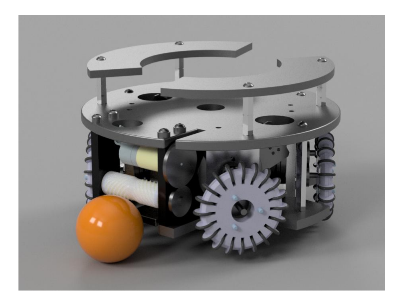
The chief design goal with the drivetrain was to efficiently integrate all the components necessary for our omni wheel drive system while also saving sufficient space for the integration of the other principal mechanisms. In order to achieve this within the space requirement for SSL, a significant amount of work went into the development of our drive system. We decided on an omni-wheel drive system as this gives us the control over movement needed to perform fast and complicated maneuvers, as well as being the league standard.
The first significant design decision for the drivetrain was motor selection. The league standard is firmly in the Maxon EC flat motor line, so the main concern was selecting the proper power rating for our use. In order to select our motor before having a prototype system, we estimated several physical and dynamic properties of the system.
Through these calculations and assumptions, we determined that the Maxon EC Flat 50 W motor, with a maximum continuous torque of 90.5 mNm would give us enough torque to achieve reasonable accelerations.
With this motor in mind, we designed the gear transmission system to bring the z level of the motor up, so as to not intersect with the first layer, as well as for it to occupy a small form factor width-wise (with respect to the motor face). The gear transmission system has a gear ratio of 1 as we simply wanted to retain the torque and speed values of the motor while shifting it upwards. The brackets used in our prototype drivetrain are 3D printed, but the final versions will be manufactured with CNC, out of aluminum.
All layers of our prototype robot are printed out of PETG - for the final version every layer will be waterjetted out of aluminum of varying thicknesses.
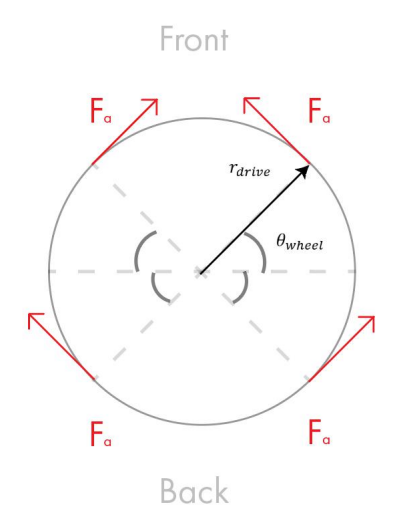
Wheel Force Calculations
$$\begin{split} m \approx 3kg; \theta_{wheel} \approx 45^\circ; r_{drive} \approx 0.07m; r_{wheel} \approx 0.025m \ n = 1 \ r_{max\ continuous} = 90.5\ \text{mNm} \ F_a = \frac{\tau_{max\ continuous}}{r_{wheel}} \ F_{wheel\ contribution\ force} = F_a \cdot sin(45^\circ) \ &= \frac{\tau_{max\ continuous}}{r_{wheel}} \cdot sin(45^\circ) \ F_{total\ forward} = 4 \cdot F_{wheel\ contribution\ force} \ a_{max} = \frac{F_{total\ forward}}{m} \end{split}$$
2.2 Kicker
The kicker subsystem was designed through an iterative process in which we identified key properties to maximize force outputted to the ball, in order to achieve the league maximum 6.5 m/s in ball speed in passing and shooting attempts.
We decided on a solenoid based design in order to have consistent kicks and to avoid significant long term wear issues, and have several parameters to work with in the design of our kicker. The main variables we worked with were: length of solenoid, thickness of casing, number of turns, turn density (turns/unit length), plunger material, spring stiffness, and travel distance.
Through readings on solenoid design [1] we identified important design considerations for the design of our solenoid.
The first component analyzed was the plunger. We made several conclusions about the characteristics of the plunger. The first is in regards to length - increased length improves energy delivery, until a level off point where the plunger is outside of the region in which the magnetic field created by the solenoid is significant. Inner radius is also examined, where the conclusion is that a solid cylinder is the best option. The outer radius is also examined, with the conclusion being that the smaller the gap between the solenoid coil and the plunger the better. Finally, through material analysis, carbon steels are determined to be the best option in terms of price compared to ferromagnetic characteristic.
Using these conclusions, we designed our plunger to be 3 inches in length, with an outer radius of 0.375 inches, and made sure to minimize the gap between this outer radius and the inner radius of the solenoid coil in the design of our casing. The material we decided on for the plunger was 1018 Carbon Steel, due to its machinability and reasonable price point. Our plunger is a 2 material composite. The kicker end is 3D printed out of PETG, and is designed to sustain the mechanical stresses present in the kicking process. The low carbon steel is lathed to fit our casing form factor and be the proper size for our desired stroke length.
In designing the solenoid coil, we discovered that the most important variable for maximizing force provided by our mechanism was turn density, something that we optimized for through our solenoid bracket design which is short in comparison to the available space on the drivetrain for the mechanism, but which allows for high turn density throughout the length of the solenoid. The bracket was 3D printed out of PETG, a light yet durable filament. The choice was made to 3D print the bracket due to the ease of rapidly prototyping to optimize certain parameters - mainly length and thickness, while also not interfering with the magnetic field produced by the solenoid coil. It's notable that our early solenoid casings were machined out of delrin, and we will likely return to this material once we are satisfied with the state of our solenoid optimization.
2.3 Kicker Energy Calculations
To determine the energy required for our solenoid we used the following calculation from the University of Technology Eindhoven [1]:
$$E_{ball} = \frac{1}{2} m_{ball} v_{ball}^2 + \frac{1}{2} J_{ball} \omega_{ball}^2$$
$$v_{ball} = 6.5 \frac{m}{s}$$
$$m_{ball} = 0.046 kg$$
$$r_{ball} = 0.021 m$$
$$J_{ball} = \frac{2}{5} m_{ball} r_{ball}^2$$
$$= 8.1 \times 10^{-6} \frac{kg}{m^2}$$
$$\omega_{ball} = \frac{v_{ball}}{r_{ball}}$$
$$= 310 \frac{rad}{s}$$
$$E_{ball} = 1.36J$$
Now that we have the energy needed to accelerate the ball to 6.5 m/s we can calculate the current and voltage needed to supply to the solenoid that we constructed:
$$E_{ball} = E_{solenoid}$$
$$E_{solenoid} = \frac{1}{2}LI^2$$
$$L = \frac{\mu_0 N^2 A_{coil}}{l_{coil}}$$
$$\mu_0 = 1.26 \times 10^6 \frac{H}{m}$$
$$N \approx 660 \text{ turns}$$
$$A_{coil} = \pi r_{cross\ section}^2 = 1.74 \times 10^{-4} m^2$$
$$l_{coil} = 0.0572m$$
$$L = 1.67 \times 10^{-3} H$$
$$I = \sqrt{\frac{2 \cdot E_{ball}}{L}} = 40A$$
$$R = 3.0\Omega$$
$$V \approx IR = 120V$$
The resulting equations show that we need a voltage of 120 V and current of 40 A.
2.4 Dribbler
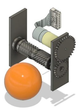
The dribbler mechanism allows the robot to maintain possession of the ball while in motion or while stationary. The two main design considerations for this mechanism are the selection and implementation of motor, and the form factor and material of our dribbling barrel.
The motor we selected is the Maxon EC 16 - with a nominal speed of 39300 RPM, we decided that we would be able to obtain sufficiently high spin speeds on our dribbling barrel for auto centering procedures, especially after the 3:2 gear ratio implemented in the transmission.
As shown in Figure 3, the bracket is made up of two parts, with one side holding both the motor and the dribbling barrel shaft bearing.
2.5 Future Work
Continued development in our drivetrain subsystem will likely be in the improvement of mechanical design and manufacturing methods for resistance to long term wear - something we have not been able to test yet. We are particularly interested in exploring better transmission systems for our drive motors in order to substantially increase our gear ratio, as well as continuing to push the compactness.
Future work on our kicker subsystem will be in optimization of our solenoid coil through testing variable kick speeds. We would also like to explore different plunger geometries and shielding methods to improve performance.
Finally, our dribbling subsystem will draw the majority of our development efforts in the future. We would like to implement a simple damping system to improve pass reception in the short term, but are highly interested in developing a higher DOF damping system for future mechanical iterations, in order to achieve optimal pass reception rates. We are also interested in investigating new material choices/manufacturing methods for our dribbling barrel to help with damping. Possibilities include silicon and rubber molds.
Electrical
The goal of the electronics subteam was to create a robust and modular electronics system for our robots, providing a seamless point of transition between our software and hardware systems. The electrical system was divided into four main subsystems: the power distribution board, the main (microcontroller) board, the motor driver boards, and the kicker board, with room for extra expansions if necessary. The purpose of our modular design was to allow the different subsystems to designed and tested separately and in parallel, and allow easy repair and replacement of individual components. Our design was inspired by ZJUNLICT's electrical design [3].
3.1 Motor Control Board
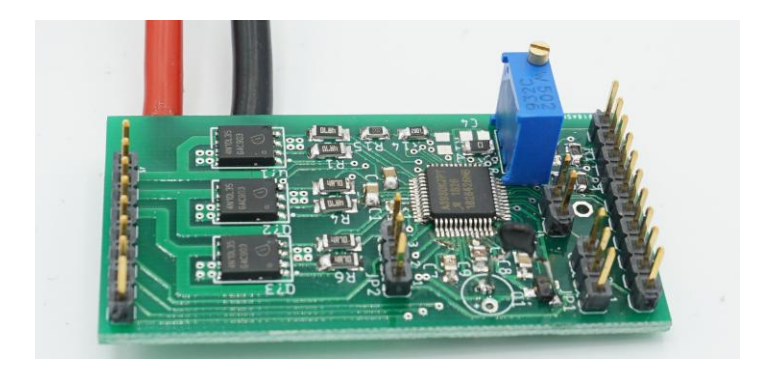
The motor control board is subdivided into four independent modules controlling individual drive motors. Each module consists of an Allegro A3930 3-phase motor driver and three dual MOSFETs to control the 3 phases of the Maxon brushless motors. The requirements for the motor driver chip were high integration for high level control with the possibility of finer control by having access to lower level signals. The A3930 can operate with a direction and PWM signal only, without requiring any other timing signal. The speed signal required for closed loop control is obtained from the hall effect sensors on the motors, which the A3930 converts to a tachometer and direction output. This simple control scheme saves processor time on the main microcontroller.
3.2 Main Board
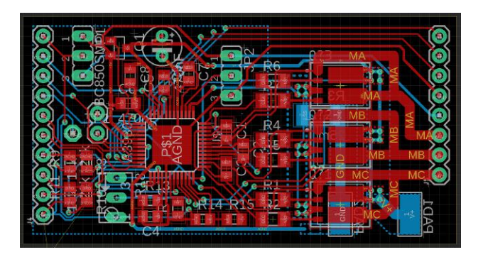
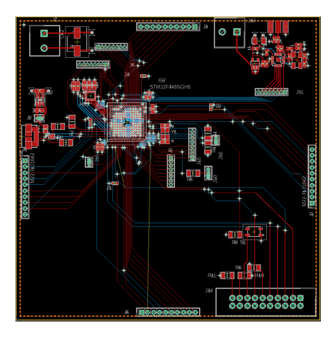
Our main board consists of a high-speed STM32F746NG microcontroller responsible for wirelessly receiving instructions from an outside black box, executing those instructions by actuating mechanical subsystems, and relaying back any relevant positional or operational data. The current iteration of the main board is a prototype built as a modular approach to testing individual parts of the system, such as the brushless three-phase motors boards or a wireless RF transceiver board. A picture of the layout can be found in Figure 6.
The board has all the onboard circuitry to support an inertial measurement unit through SPI, broadcasting data through an external antenna, and communicating to four motor boards. Additionally you can find connectors and setup for USB 1.x FS and JTAG, mostly for debugging purposes and for bootloading or updating firmware.
We are currently using STMicroelectronics development kits to control most of our systems, so the driving idea behind the board's design was to offer a similar set of tools — ample amount of general purpose pins, setting multiple ways of communicating to and from the microcontroller (USB, USART, I2C, SPI, JTAG), and header or jumper pin style connections for ease of on-the-fly pin-swapping. In the future, we'd hope to transition to a more concise version versus a one-size-fits-all solution.
3.3 Power Distribution Board
The power distribution board's main task is to convert and distribute the battery power input across all components of the board. The nominal battery voltage is used to supply the most power intensive components, the drive motors and the kicker board, to get the best performance because no power conversion is needed. Additionally the nominal voltage will be stepped down using to provide 12V, 5V, and 3.3V lines for the dribbler motor, the microcontroller board, and any other necessary components. Buck converters will be used to create the 12V and 5V lines for high efficiency conversion, then a linear regulator will be used to create the stable 3.3V line for the microcontroller. Additionally, the power distribution board will provide voltage and current monitoring and protections and an emergency stop function to help prevent damage to other components in case of transients or current spikes.
3.4 Kicker Board
The kicker board's main role is to provide the high instantaneous current and voltage necessary to drive the kicker solenoid. This is accomplished by using a boost converter to charge up a capacitor bank to 200V, then quickly discharging the capacitors into the solenoid windings to provide the large current and magnetic field needed to kick the ball with a large force.
3.5 Future Work
Our future work will consist of further testing and revision of all of our major subsystems and adding the necessary improvements and protections. Our next steps will be to finalize the kicker board design, conduct a redesign of our motor drive systems to increase robustness and prevent damage, decide on our nominal voltage input, and to test the full integration of the major subsystems. We will be looking into combining the individual motor drive boards into one complete board that can handle the entire drive train, allowing for a more compact design and more concentrated power distribution. We also need to prevent issues with the motor back EMF destroying our motor drive ICs. For the power system, we need to decide on batteries, and whether we want to use a 16V or 36V nominal voltage, trading off between driving our 36V motors or getting new motors but eliminating the need to create special batteries for the robots. Additionally, we are waiting for the arrival of our microcontroller board to test full integration.
Software
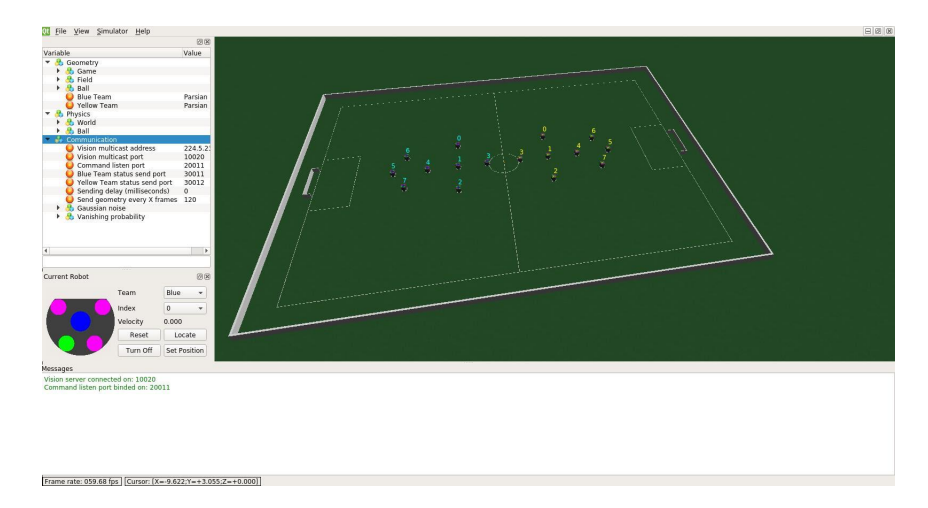
Our goal for the software team in these first couple of months was to set up initial prototypes of the controls, path planning, and strategy modules. We also studied the existing ssl-vision system in order to familiarize ourselves with how to operate it and possible improvements we could make in the future. Since we just started the competition, we weren't able to test on real prototypes of the robot for most of this time, so we focused on using the grSim simulator (Figure 7) to test our approach and familiarize ourselves with the environment. In order to simplify integration on real robots, we emphasized simplicity and robustness in our initial approaches while also leaving room to add complexity later.
4.1 Controls
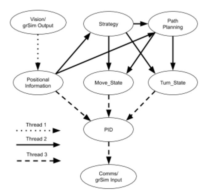
Due to the complex nature of the game, we anticipated that the robots may be required to move in a multitude of different ways, so we implemented a limited Finite State Machine (FSM) model for each of the robot's turning and lateral movement objectives. This allows us to command the robot using open and closed loop control to move in both a general direction and directly to a set location. We use PID control to quickly and efficiently guide the robot to specific locations. Likewise, we control the rotation of the robot either by rotating to face a specific direction or by indefinitely rotating at a given angular velocity. These commands are called by the strategy module to execute the chosen actions. In anticipation of slower path-planning algorithms, we opted to run each software component separately to ensure that the robot would always be in control and not colliding with other robots. A diagram of our software structure is shown in Figure 8.
4.2 Path Planning
Due to the many unpredictable obstacles on the soccer field, it was important for our robots to have a fast and adaptable path-planning system so they could avoid collisions and successfully navigate to locations as determined by the strategy. Since this is our team's first year participating in Robocup, we decided to begin by surveying other teams' TDPs to determine what was currently being used. We found that many teams relied on a variant of RRT*, which was favored due to its high-speed and performance. In the end, we settled on implementing RRT-X, an RRT* variant designed for path-planning in unpredictable environments [4]. We wanted to implement the RRT-X algorithm that builds upon RRT* to optimize for highly dynamic environments in order to contribute new research to the Robocup community, since we did not find any other team using this algorithm. We plan on doing a full comparison between RRT* and RRTx once we test on real robots.
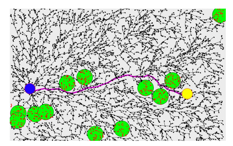
The path-planning module interfaces into the rest of the codebase via taking in a goal location and the current state of the obstacles, and outputting a sequence of waypoints for the robot to follow to reach the goal. The tree is repeatedly updated with new obstacle information as the robot travels, and it rewires itself accordingly and produces new waypoints to follow if needed. A sample path generated by RRT-X can be seen in Figure 9. Obstacle information for the path-planning module is provided by processing input from ssl-vision.
4.3 Strategy
Our initial approach to strategy is to give each robot a role and to define objectives for each of these roles. This framework will allow for more complexity in the future as we develop more complex behaviors for roles and robots are able to switch roles. Currently, the three primary roles for the robots are Goalie, Attacker, or Defender. Each robot plays based upon a straightforward decision tree to determine the immediately optimal action to take.
The Attacker is the closest robot to the ball and is sent to gain possession. Should the robot be within range of the goal and the line of sight between itself and the goal be open, it attempts to score. Otherwise, the robot passes if safe to do so or continues dribbling. Defenders guard the nearest enemy robot in reference to the Attacker, and the Goalie is responsible for blocking the opponents attempts to score.
4.4 Future Work
Most of the work we have done from the software side has been laying the groundwork for our codebase and focusing on low-level control of the robot: processing sensor data, controlling motors, and working on being able to move the robots autonomously from point to point. As we have managed to make good progress on these fronts, our future software work will focus on developing higher-level behaviors in our robots, such as ball control, goal-keeping, and general strategy work. In order to accomplish this, we aim to run more testing of our strategy software and create tools to iterate over many different strategies efficiently.
To more efficiently control our movement around the field, we plan to continue tuning PID and improve upon our current methods of translating our robot's location. For our path-planning module, we plan to work on optimizing our tree-rewiring times so it can be used effectively in real-time scenarios. An important part of this will be optimizing the RRT-X hyper-parameters for our field size, obstacle size, and robot kinematics.
During our survey of other teams' TDPs we noticed that many teams apply filters to the camera feed in addition to using ssl-vision and we plan to explore this more in the coming months in order to improve the reliability of our positioning data.
Acknowledgements
We wouldn't have been able to make so much progress without the RoboCup community for the extensive information put online in terms of EDTP, TDPs and GitHub repositories. We would also like to thank Juan Almagro of RoboJackets and Kendall Zhu of the Harvard Undergraduate Robotics Club for answering our questions on how to get started.
We would also like to thank the MIT Edgerton Center and MIT UA Financial Board for their support and guidance, and we would like to thank STMicroelectronic for their material support.
References
- Goch, B. (2006). Optimizing a solenoid for a Robocup kicker. (DCT rapporten; Vol. 2006.051). Eindhoven: Technische Universiteit Eindhoven.
- RoboJackets. (2019). 2019 Team Description Paper. Georgia Institute of Technology.
- ZJUNlict. (2019). ZJUNlict Electronics Design for the RoboCup Soccer Small-Size League. https://github.com/ZJUNlict/Electronics.
- Otte, M.W., & Frazzoli, E. (2014). RRT-X: Real-Time Motion Planning/Replanning for Environments with Unpredictable Obstacles. WAFR.