OMID 2020 Team Description
Mohammad Hossein Zolfaghari Abir, Hashem Khan Mohammadi, Kevin Babakhanluo, Mohammad Mahdi Kamalkhani, Alireza Sahebi, Farhad Najafi, Amirmohammad Karimi Forood, Ali Mollajafai, Mohammad hossein Zahedi, Omid Mahdizadeh, Javad Rahmani, Vahid Akbari, Maryam Akhoundian
Department of Biomedical Engineering of Shahed University of Tehran, Iran; Department of Electrical Engineering of Shahed University of Tehran, Iran; Department of Mechanic Engineering of Amirkabir University of Tehran, Iran; Department of Computer Engineering of Shahed University of Tehran, Iran; Department of Electrical Engineering of Tehran University of Tehran, Iran; Department of Electrical Engineering of Khaje Nasir University of Tehran, Iran; Department of Electrical Engineering Islamic Azad University Science and Research Branch; Department of Computer Science of Shahed University of Tehran, Iran
Abstract This paper is an explanation of recent technical improvements of OMID, a small size league team intending to participate in RoboCup 2020 in Bordeaux, France.
Introduction
Omid Robotics Team (ORT) began small size team in 2007. ORT has been participated in competitions since 2007 as a branch of robotics society of Department of Electrical Engineering of Shahed University located at Tehran, Islamic Republic of Iran.
Section 2 represents new mechanical system and improvements of robot control. Section 3 represents improvements that we made in electronics, including FPGA VHDL code enhancements. Section 4 represents new decision layer in our software to control the behavior of our robots including placement and passing in the field.

Mechanical system
In this section, we will explain the design improvements of Omid team small size robots. The proposed scheme is more agilent and has better performance to cost ratio. The design have changed drastically according to previous one. In section 2.1-2.6 more explanation are accessible.
Motor and encoder improvements
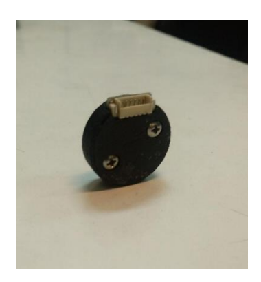
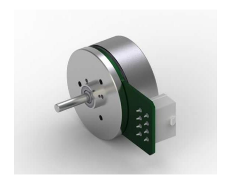
In previous version, the motor power was found insufficient. The new control algorithm requires more agile system and powerful actuator. To rectify the problem, we decide to improve the motor power from 30 to 50 watt and use higher-resolution encoder on motor shaft. The new encoder is magnetic type and has 8 times higher resolution than old one (12bit). The new motor is EC-45 flat (brushless, 50 watt), produced by Maxon motor corporation.
Wheel layout configuration
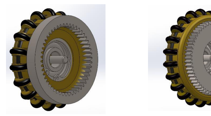
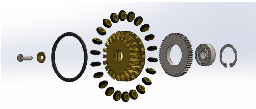
The previous wheel implementation was designed such that the front pair has different installation angles compare to back one. It makes the control more difficult. To prevent the difficulty of control algorithm in new version, we install the wheels with 90-degree difference compare to each other. The resulted configuration is symmetric. The wheel back-gear also changed from exterior tooth to interior one. The number of sub-wheels increased from 18 to 22 and the wheels diameter increased to 50 mm. More detail is accessible in figure 2 to 4.
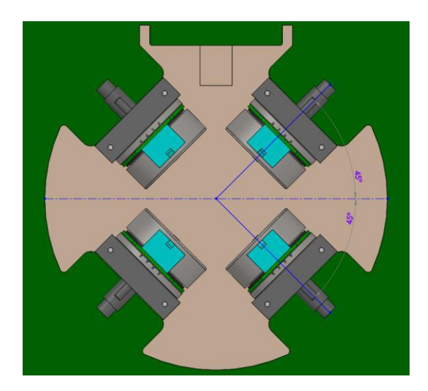
Motor configuration
The lack of space due to new motors, made the design more challenging. At last, it was decided to install motor in higher level than the wheels in new version. The details are described in figure 5.
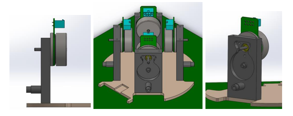
Motor and wheel interaction mechanism
The height level difference between wheel and motor, gives us an opportunity to implant a gearbox between them without allocating a separate space for it. The gear was designed uniquely to meet the mechanical constraint. Figure 6 represents it in more details.
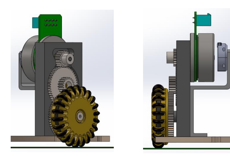
Capacitor and battery layout design
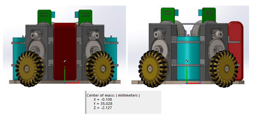
The capacitor and battery were placed above the motors in previous version but we cannot do the same in new design due to rising of center of mass. To prevent the COM height rising, the capacitor and battery placed vertically near the motors in unoccupied spaces. Figure 7 shows better the design efficiency in lowering the COM height.
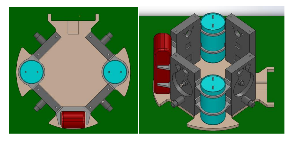
Plunger design improvement
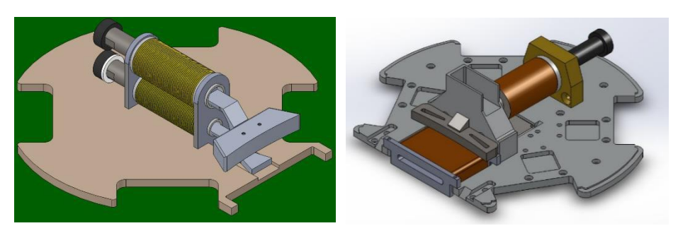
The plunger shape and size changed to make it more impact. The placement was designed such that the winding improvement could be possible. Two cylindrical solenoids were used to actuating the plunger. The previous solenoid was rectangular and lower than new design. To prevent the striking of plunger into the ground, we decided to rise the solenoids height. more detail shown in figure 8.
Center of mass
Conclusion
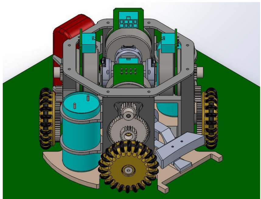
After assembling the parts in SolidWorks, the final robot body was achieved. It is presented in figure 9. We are still working on the mechanic and the next step is designing the damper system.
Electrical System
Improvement of FPGA VHDL code
In movement of wheels of robot, we had a problem, which causes one wheel to start to move earlier than the other ones. We guessed that the problem arises from the delay between switching on/off the motor MOSFETs. To fix this problem, we first created a separate module in VHDL code of FPGA for motors. Then we used the XILINX chip scope and chose the motor MOSFETs and encoder as the input for the chip scope tool, and by delineating their graphs on the chip scope, we realized that we need to increase the delay between switching of the motor MOSFETs.
In robot kick system, most of the kick IGBTs have been damaged when robot kicks the ball. For solving this problem, we reduced the PWM that we used for determining kick power in FPGA code, so that we could have the most firepower without damaging kick IGBTs.
Software
Decision layer
Due to taking long time of implementing previous decision layer described in last year TDP [2], we decided to implement new decision layer in parallel to implementing previous one.
We have implemented two algorithms, one for robot placement in field and the other for automatic passing of robots.
The placement of teammate robots in the field has two modes, attack mode and defense mode. These placements depend on different factors, so we use sum of the value of each factor that shows occurrence of factor [3]. Each value multiplied by a coefficient derived from tests performed practically. Equation 1 shows this summation. shows worthiness of a position for robot to be placed, function gets the value of factor for a position and is a coefficient for factor .
$$score(pos) = \sum_{i=0}^{\infty} a_i * val_i (pos)$$
Attack mode
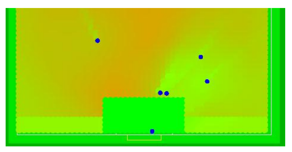
In this mode, we seek for appropriate positions that our robots could get so that it could get scoring chance. We divided field into tiny equal zones, and for the center of all these zones, we compute , the summation of multiplied values that each shows the occurrence of a factor. Selecting a zone depends on various factors such as distance from the opponent goal, successfulness of pass to robot in the zone and dispersion of teammate robots in the area around of zone. Figure 10 shows field with colorized zones that indicates of zone.
We sort these s in decreasing order, so the destination of our attacker robots would be the zones with highest probabilities.
Defense mode
In this mode, we select the most dangerous robots based on factors such as robot position, robot orientation, dispersion of teammate robot and free space of opponent robot to our goal. Then we cover the free space between the dangerous robot and our goal using our robot, so that the scoring chance would be denied.
Passing
To pass a ball to our attacker robot, which are located in the appropriate zones in attack mode, we calculate the probability of successful pass to each robot based on factors such as distance of robot to opponent goal, distance of ball to robot and free space of robot to goal. Then we sort these probabilities in decreasing order and the robot with highest probability would be selected to pass.
References
- https://www.xilinx.com/support/documentation/sw_manuals/xilinx14_6/ug750.pdf: ISE Tutorial: Using Xilinx ChipScope Pro ILA Core with Project Navigator to Debug FPGA Applications
- Omid Robotics Team.: OMID 2019 Team Description paper. Technical report, ECE Department, Shahed University of Tehran.
- LE, Chap T.; EBERLY, Lynn E. Introductory biostatistics. John Wiley & Sons, 2016