PARSIAN 2020 Extended Team Description Paper
Mohammad Reza Kolani, Hossein Sharifzadeh Behzadi, Mahdi Hajimohammadi Onidin, Yasamin Alizadeh Gharib, Mohammad Mahdi Malverdi, Kasra Khalafi, Kian Behzad, Mohammad Azam Khosravi
Electrical Engineering Department Amirkabir Univ. Of Technology (Tehran Polytechnic) 424 Hafez Ave. Tehran, Iran
http://www.parsianrobotics.aut.ac.ir
Abstract The Current paper issue to qualify as participation in the RoboCup 2020 small size league. It illustrates detailed mechanical, electronics, control, and software improvements made by the Parsian Small Size Soccer team since last year. The notable mechanical change is changing the internal wheel's gear with external gear, redesigning the spin mechanism, designing a dust protector, using silicon X-ring instead of silicon O-ring, and changing the material of the board holder to reduce weight and height of the robot. Likewise, some improvements have been made in the electronic FPGA project and a review of Electronic boards. We used a voice recognition package named Pocketspinx to control robots and new rules to better code documentation.
Introduction
The Parsian small size team, founded in 2005, is organized by the Electrical Engineering Department of Amirkabir University of Technology. The Parsian aims to design robots compatible with International RoboCup 2020 rules. This team has been qualified for 14 preceding years in RoboCup Small Size League. The most significant achievements of the Parsian are first place in RoboCup2012 Passing and Shooting technical challenge, first place in RoboCup2013 Navigation technical challenge, and fourth place in RoboCup2012 and 2017. Section 2.1 represents some mechanical changes in our robots. Then in section 2.2, electrical design features have been explained. At last, section 3 introduced the software improvements and novel tools that we started to use.
Hardware
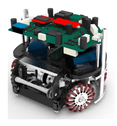
This section covers the mechanical and electrical improvements made to the PARSIAN robots for the 2020 season.
Mechanic
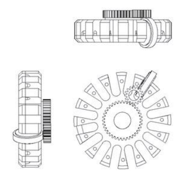
Changing Wheel's Gear. This year, our mechanical designer decided to change robot wheel's gear completely. In old design, internal gears have been used and caused the following problems:
- It was challenging to build internal gear with these dimensions.
- The smallest eccentricity of gears would lock the wheels.
- A large amount of carpet lint envelope accumulated inside the gear and disturb the robot's movement.
- Complicated assembly and engagement with the motor's gear
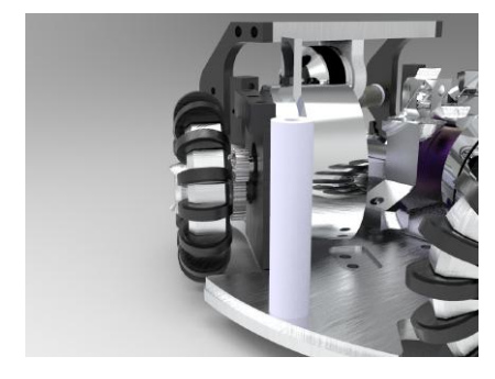
Therefore, to solve these problem, the calculations were done to determine the external gear with a larger conversion ratio. To be able to move faster on a larger ground and this was not possible with the internal gear. The wheel technical drawing views and assembly on the robot are shown in the following figures.
Redesign dribbler system mechanism
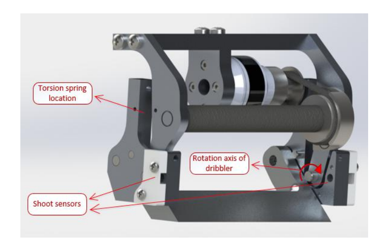
In the previous mechanism of transferring power from the dribbler system's motor to the spin back rod, a timing belt and pulley were used, which had many problems including:
- Rapid tearing of timing belt and the loss of the robot the spin during games
- Extremely high timing belt and rod spine vibration because of 12000Rpm spin motor's speed.
- Generate very undesirable noise when using spin.
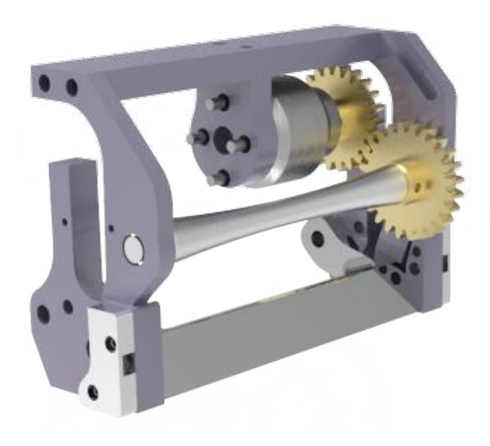
Finally, the gear system was designed and tested to overcome the problems mentioned above. This design uses 1mm modular brass gears with a conversion ratio of 1.5, which reduced the motor speed to 8000 rpm. Also, the torque transmitted from motor to the spin's rod, in this case, is 1.5 times larger than the previous one.
Dust Protector
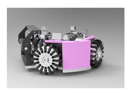
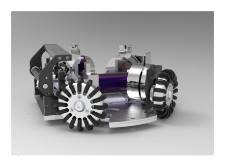
One of the significant problems in our robots and maybe other SSL teams is the entrance of carpet lint in robot and disturb the robot's mobile systems such as chip and kick. Therefore we tried to design parts that Prevent entering lint, this protector made by a 3D printer.
O-rings
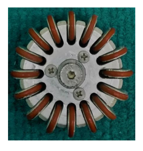
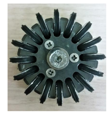
This year our mechanical designer decided to use silicon X-ring instead of silicon O-ring. X-rings have a more significant coefficient of friction between the wheels and the ground Compared to the previous O-rings.
Changing of board holder material
In order to reduce the weight and height of the robot, we decided to lighten the robot's parts. For this reason, The material of the board holder changed from Polymethyl methacrylate(plexiglass) to fiberglass, which caused reduced the robot's weight 30 grams. Due to the high yield stress of the fiberglass, we were able to use a thinner holder instead of the old one, which reduced 5mm the robot's height.
Electronic
Interfacing to the Top-Level Schematic using Open-bus module. Altium designer (in the previous versions that supported FPGA projects), providing a module named open-bus. With the OpenBus System defined, we now need to interface the OpenBus System document with our top-level schematic.
Open-bus has many advantages:
- It helps the FPGA Project to be more understandable and readable.
- The open bus makes changes and configures easier and more manageable.
- Using the open bus prevents using many interconnects, and more can be implemented in one interconnect inside an open bus by setting the appropriate configuration.
- Instead of all components in a ".Openbus" file even like TSK3000 processor we can use a single block in.
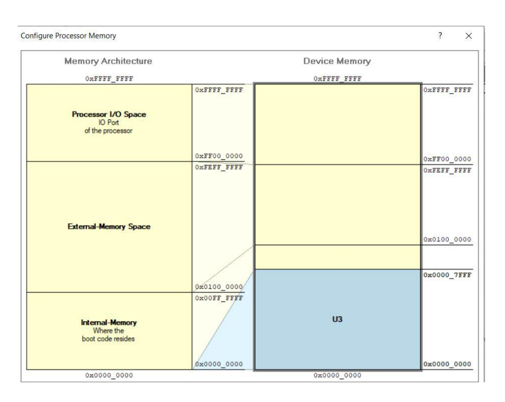
- Linking the associated Embedded Software project and ensuring the Application Memory mapping is defined as required. This mapping is defined as part of the embedded project options and determines how the embedded software uses the mapped physical device memory blocks.
- Configuration of the FPGA project to target the required physical FPGA device can be achieved most efficiently using the auto-configuration feature (including assignment of applicable constraint files).
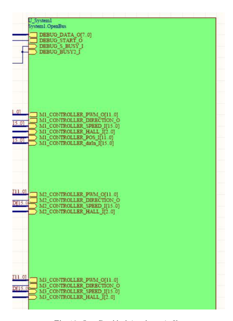
In order to add this module first, we made an open bus module and tried to move all parts after TSK3000, including all interconnects and output parts, which will connect to other outer components, both input, and output pins.
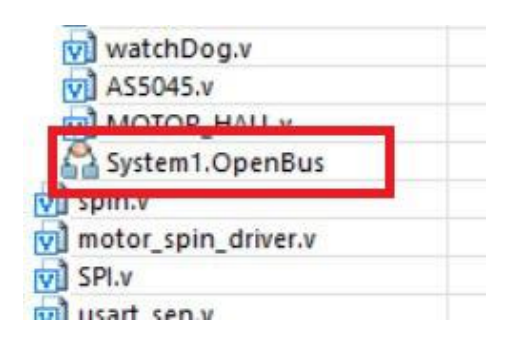
Openbus Design
The sheet entries required to populate the sheet symbol; it can be obtained through the use of the sheet entries and ports synchronization feature. At the heart of the OpenBus System is the OpenBus System document. This document is created and managed using Altium Designer's OpenBus Editor.
The OpenBus Editor has the familiar look and feel of Altium Designer's Schematic Editor, with a streamlined set of resources applicable to the creation of an OpenBus System. Filtering and inspection are provided courtesy of OpenBus Filter, OpenBus Inspector, and OpenBus List panels, accessed from the OpenBus panel access button to the bottom-right of the main design window.
OpenBus System Components
It contains graphical representations of all devices available for use in creating the system, grouped into the following four categories:
- Connectors – provides Interconnect and Arbiter components that are functionally similar to the WB INTERCON and WB MULTIMASTER devices in the schematic world. Additional components allow for bus interface signals to be exposed outside of the OpenBus System document. A termination port is also provided for occasions when a master port is not being used and should be appropriately terminated. (if you do not, it can make some issues in compiling the code as we faced some.)
- Processors provides all of the 32-bit processors supported by Altium Designer.
- Memories provides memory controller devices.
- Peripherals provides all of the I/O peripheral devices available for design.
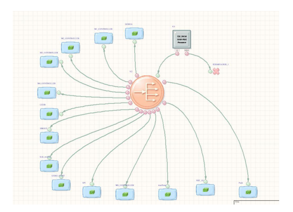
The Interconnect component provides a means of accessing one or more peripheral devices over a single OpenBus interface. It connects directly to the IO or MEM ports of a processor component, facilitating communication with I/O peripherals or physical memory devices, respectively. All ports from the OpenBus System document will be initially listed as unmatched ports. The ports themselves come from two places: Ports automatically derived based on the external interfaces of the peripheral devices (I/O peripherals and memory controllers). In the OpenBus Signal Manager dialog, ports derived from the clock and reset line definitions.
Schematic Implementation
In the main schematic file, we can add these features as a block that provides all inputs and output ports. Then we connected to output and input ports to other blocks like what it was in the previous version. When using the dialog to add sheet entries to the sheet symbol, it is a good idea to select each bank of related ports in turn, rather than all ports at once. This idea will make the placement of the sheet entries within the sheet symbol that much easier.
Memory and Peripheral Configuration
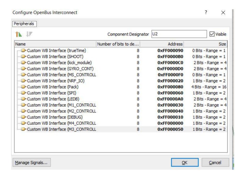
After all of this, we should have reset the memory mapping configuration of TSK3000 and peripheral mapping related to both processors and interconnect components in order to make sure that nothing is going to make any problem.
Software
According to Parsian TDP in 2018, Parsian's AI code was migrated to the Robot Operating System (ROS) framework. From last year we started to figure out different advantages and tools that we are capable of ROS.
PocketSphinx package using for voice commands
PocketSphinx is one of Carnegie Mellon University's open-source large vocabulary, speaker-independent continuous speech recognition engine. The CMUSphinx team describe the application of their product like this:
"Such applications could include voice control of your desktop, various automotive devices, and intelligent houses. Other possible applications are speech transcription, closed captioning, speech translation, voice search, and language learning."
You can find this open-source package in the available links.
First of all, we should have installed the ROS version of PocketSphinx and join it to other nodes of our control project.
To install the PocketSphinx ROS package, there is a standard package which "wiki.ros" has published. However, the problem was that this package is available just for ubuntu 14.04 and ROS indigo, whereas Parsian Robotic uses version 16 of ubuntu and ROS kinetic. CMUSphinx team again has developed a package available for groovy, hydro, indigo, kinetic, and lunar versions of ROS.
Finally, after some little issues relating to installing some other required packages, we could run this package on the kinetic platform, and we used this speech to text machine for recognizing voice commands and generating text as an output.
It used a dictionary and language model to recognize the words and phones in the speech. We streamed output of this recognition engine and mapped words like "move", "forward", "back", "backward", "right", "left" to real commands for robots and this way we could control them by voice instead of using keyboard interaction or joystick while testing or any other times we need to control manually.
Special thanks to the sphinx team of Carnegie Mellon University for their great support.
Code documentation
Obviously, through years in a software team, team members change. It is needed for a software team especially a robotic team to have strong and rich documentation near version control for their valuable codes. since 2015 Parsian team started to use Github as version control. but for code documentation, we spent a lot of time to hand over each domain from one old team member to new team members. sometimes this procedure took a long time and some times it wasn't even possible. especially last year suddenly some of our most critical team members should have left the team and there was not enough time to hand over all of the skills and responsibilities. so we started to make complete, clear, obvious and strong documentation for each part of code and we decided to refuse to accept any task without revision it's documentation. In this way, we started using some new tools. you can find some of them with brief details as below:
- Dropbox Paper: For internal software documentation use, Dropbox Paper is an excellent choice. Like its predecessor Hackpad, you can use it to create a private wiki for employees. You can link documents together, insert code blocks, images, and page jumps, just as you'd demand from any documentation tool.
- Doxygen: Doxygen generates latex an HTML documentation from annotated C++ sources, but it also supports other popular programming languages such as C, Objective-C, C, PHP, Java, Python, IDL (Corba, Microsoft, and UNO/OpenOffice flavors), Fortran, VHDL, Tcl, and to some extent D.
Software Team Rules
Here are some of our rules in software team:
- naming: The name of variables and any other objects should be a standard abbreviated form of meaningful words and even phrases, in case of need.
- class definition: Any defined class should have brief details including the number of inputs and outputs and type of inputs and outputs and what it does.
- common class dictionary: any function or class which is used in more than one section whether it is from a public library or not should be added to a dictionary contains names of functions or classes near the definitions in the previous case.
- commenting: each part of code that contains an independent functionality and each block of code that has some complexities like nesting loops should have a separate comment.
- beneficial comments: comments should be precise and relevant and should involve anything that can affect the functionality of relating part of code.
- maintaining comments: through code changes, comments should be kept up to date and they have to change along with the code.
Conclusion
This year our mechanical changes aimed to stabilize dribbler system and improve power transfer system. In the electrical section, some minor changes have been applied in order to reduce some systematic errors and Open bus added to increase portability and readability of FPGA project. In addition, we started using tools like pocketsphinx, and also some rules has been made to better code documentation In the software section.
References
- Alireza Zolanvari, Mohammad Mahdi Shirazi, Seyede Parisa Dajkhosh, Amir Mohammad Naderi , Maziar Arfaee, Mohammad Behbooei, Hamidreza Kazemi Khoshkijari, Erfan Tazimi, Mohammad Mahdi Rahimi and Alireza Saeidi Shahrivar. Parsian 2015 Extended Team Description Paper for RoboCup. (2015)
- Kian Behzad, Elham Daneshmand, Nadia Moradi, Mohammad Reza Kolani, Mahdi Hajimohammadi Onidin, Yasamin Alizadeh Gharib, Atiyeh Pirmoradi, Mohammad Mahdi Rahimi, Mohammad Mahdi Shirazi, and Mohammad Azam Khosravi. Parsian 2019 Extended Team Description Paper for RoboCup. (2019)
- Altium designer, Open-bus, https://techdocs.altium.com/display/FPGA/OpenBus+Tutorial+- +Interfacing+to+the+Top-Level+Schematic
- Rahimi, M.M., Shirazi, M.M., Gholyan, M.A.N., Chaleshtori, F.H., Moradi, N., Behzad, K., Roodabeh, S.H., Gavahi, A., Farokhi, F., Moghadam, S.A.G.A. and Gharib, Y.A., PARSIAN 2018 Extended Team Description Paper.
- cmusphinx - pocketsphinx, https://github.com/cmusphinx/pocketsphinx
- Carnegie Mellon University - cmusphinx , cmusphinx.sourceforge.net.
- pocketsphinx - ROS Wiki,http://wiki.ros.org/pocketsphinx
- /github.com/cmusphinx/ros-pocketsphinx/tree/kinetic-devel - pocketsphinx, https://github.com/cmusphinx/ros-pocketsphinx/tree/kinetic-devel kinetic
- Rahimi, M.M., Shirazi, M.M., Arfaee, M., Gholian, M.A.N., Zamani, A.H., Hosseini, H., Chaleshtori, F.H., Moradi, N., Ahsani, A., Jafari, M. and Zahedi, A., PARSIAN 2017 Extended Team Description Paper.