RoboCIn 2020 Team Description Paper
Cecília Silva, Charles Alves, Felipe Martins, João Gabriel Machado, Juliana Damurie, Lucas Cavalcanti, Matheus Vinícius, Renato Sousa, Riei Rodrigues, Roberto Fernandes, Ryan Morais, Victor Araújo, Washington Silva, Edna Barros, Hansenclever F. Bassani, Paulo S. G. de Mattos Neto, Tsang Ing Ren
Centro de Informática, Universidade Federal de Pernambuco
Abstract RoboCIn has been participating in Latin American Robotics Competition (LARC) since 2016 and competed for the first time in the RoboCup in 2019. In this paper, we present our new robot version intending to attend the Small Size League (SSL) in RoboCup 2020 in Bordeaux, France. The main focus of this paper is to detail our improvements in the mechanics, sharing our experience trying to develop almost the entire robot 3D printed, our electronic system enhancements, as well as the strategy and software development. We hope to contribute with the league showing our successful experience with a 3D printed robot in two competitions and our approach to optimize the communication with the base station by using Ethernet protocol instead of Serial protocol.
1 Introduction
RoboCIn is a robotics research group from the Federal University of Pernambuco (Universidade Federal de Pernambuco - UFPE), Brazil. In 2018 we started to develop our first robot to compete in the Small Size League (SSL). Last year, we participated for the first time in this league in Sydney, Australia, and achieved third/fourth place in Division B. The team also participated in the Latin American Robotics Competition (LARC) in 2019 held in Rio Grande, Brazil. Participating in these competitions give us some insights on what we can improve on our project to achieve a more reliable 3D printed robot.
In this paper, we will describe our improvements during the last year, and also discuss some ideas we intend to implement for the next RoboCup. The remainder of this Team Description Paper (TDP) is organized as follows: Section 2 describes the mechanical design, which shows a complete redesign compared with our last TDP, especially with changes and tests in the Dribbler and Kicker mechanism. Section 3 explains our new embedded system design, all the changes in the electronic project due to communication issues, and a new base station with a communication approach using Ethernet. Section 4 shows our user interface, which was built from scratch and a new approach to improve our pass skill. Section 5 summarizes our work and proposes future works.
2 Mechanical Design
During the last year of development, the team faced some problems with certain 3D printed parts and then decided to project and produce a new and more reliable robot, and Section 2.1 will discuss these changes. The team designed the robots using Autodesk Inventor 2020 and then printed these parts using a Prusa Mk3 3D printer [3]. Our focus on using 3D pieces for all the structure was to reduce costs and decrease the number of machined parts. All 3D printed parts were tested under game running conditions to check their reliability and to make sure they wouldn't break easily during the matches. This section will cover our new robot design, our new omnidirectional wheels, the improvements in our kicker mechanism, and our dribbler issues that we are trying to overcome for ball handling. Our robot specifications can be found in Table 1.
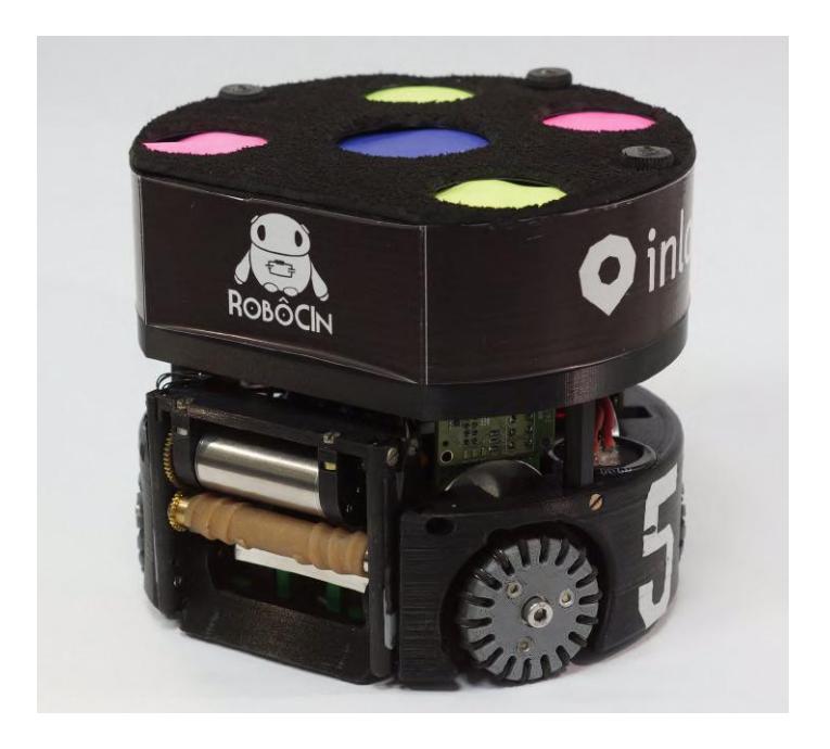
Table 1. Robot Specifications
| Robot Version 2019 | 2020 | |
|---|---|---|
| Driving motors | Maxon EC-45 flat - 50W | |
| Max % ball coverage | 19.55% | |
| Microcontroller | STM32F767ZI | |
| Gear Transmission | 18 : 60 | |
| Gear Type | External Spur | |
| Wheel | GTF Robots SW-504 | 3D Printed |
| Total Weight | 2.44 kg | 2.53 kg |
| Dribbling motor | Maxon EC-max 22, 25W | |
| Encoder | MILE 1024 CPT | |
| Dribbling Gear | 50 : 30 | |
| Dribbling bar diameter | 15mm | 14mm |
| Max. kick speed | 6.5m/s | 8m/s |
| Communication Link | nRF24L01+ | |
| Battery | LiPo 2200mah 4S 35C |
2.1 New 3D Printed Robot
The chassis of our new robot has two floors, Figure 1 shows our robot. For the First Floor, we have decided to use a single 3D printed piece, using the Immortals' Open Source contribution [1] as an inspiration to our new design. It holds the four locomotion motors, two capacitors, the kicker mechanism, the dribbler mechanisms, and the battery. It takes 30 hours to print, using Polylactic acid (PLA) filament and 20% of infill.
One major issue with our initial First Floor design was the capacitor placement, which was partially exposed in the first version and suffered some impacts during some games, presenting the risk of explosion. To fix these issues, we have reduced our dribbler bar length and moved the front motors, to free up some space to place the capacitors completely inside the chassis. In future versions, the plan to use a configuration with 45° between the wheels to have better use of the space on the First Floor.
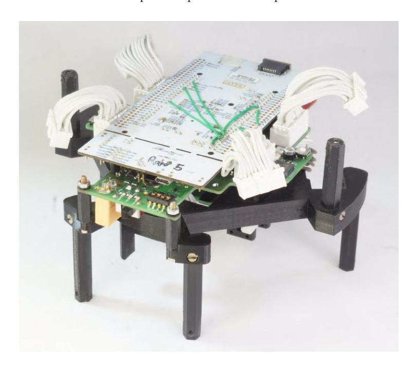
Figure 2 shows the 3D printed the second floor, which holds the mainboard and kicker board, and its design is to optimize the space in use to fit the robot into the limits. We use four 3D printed standoffs to attach the second and the first floor, maintaining the same height for the battery placement and avoiding to touch the motors. The biggest challenge on this floor was size constraints and how to make it easy to repair inside parts, as the boards and the motors.
To cover our robot we use a single 3D printed piece, that holds the color tags and provides protection for the second floor. This cover is attached to the second floor using two 3D printed bolt holders that make handling easier.
2.2 Omnidirectional Wheels
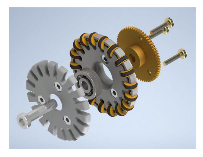
The team decided to redesign the omnidirectional wheels to fit our robot space requirements. We took the steel rollers of our previous wheel and designed two 3D parts to hold the shaft, bearing, gear, and rollers. In Figure 3, it is possible to see an exploded view of our 3D printed wheel. The two parts were printed using PLA and 100% infill to increase resistance. We decided to use 18 rollers to keep the robot moving fluidly without shocks during the transition from one roller to another.
Although increasing the number of rollers improves the performance, it makes the 3D printed parts weaker and more breakable. To fit the rollers we use a 48.5mm diameter wheel, and single aluminum wire with a diameter of 1.65mm to hold the rollers. We choose to use a single cable to prevent the loss of rollers during the matches, even if the 3D part breaks. We had to modify our gears to enlarge the hole diameter, and we opened three holes with 3mm spaced 120° to cross three bolts through it so that it could be attached to the wheels.
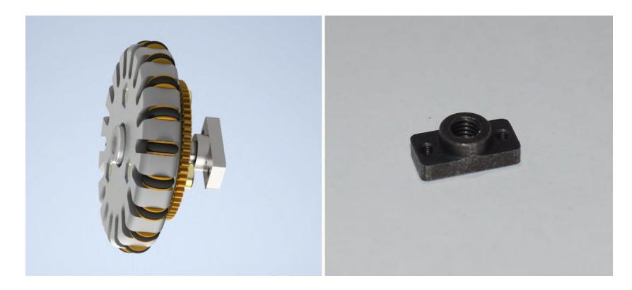
We use a M5 modified bolt to fit the bearing and to attach the wheel to the First Floor. In 2019 we had an issue with gear backslash due to deformation in our First Floor. We used an M5 nut to hold the wheel, and this nut was slowly creating a gap inside the First Floor. Figure 4 shows a special nut produced to fix this issue. It has two M2 screw threads to hold the nut in its position, avoiding the gap into the First Floor and keeping the gearing quality.
Overall, the 3D printed omnidirectional wheel proved very reliable during the two competitions in which the team attended, at RoboCup 2019 only two wheels required 3D parts replacement and only one during LARC 2019. The first version of the wheels used brass rollers, but during the competition, the team lost some of them and then decided to change to steel rollers. Another issue was the dust and fragments of the field disturbing the gearing, and we had to clean the wheels after every match and training session.
2.3 Improvements in Kicker Mechanism
Our experience with 3D printed plungers was not the best. In the team's last TDP, we presented a 3D plunger with a M8 bolt at the back. Although we were able to design them reliable, the maximum ball speed was around 5m/s with a fully charged capacitor. The team observes two problems with this kicker, firstly the time to fully charge the capacitor between each kick was too long, and secondly, it was unable to use the chip kick because it could not go over another robot.
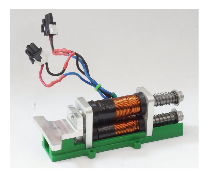
To solve this issue, we studied other team's open-source contributions and tried to implement a solution based on Tigers kicker mechanism [6]. Our plunger design used two parts, one non-conductive in aluminum and other conductive in steel, both with a diameter of 10mm. The team adapted the coil to the new solution, and it has around 400 turns.
Figure 5 shows an overview of the new kicker mechanism. We used a compression spring to return the mechanism after the kick. We use a galvanized wire with the following parameters: 0.81mm diameter, mean diameter of spring 12mm, the pitch of spring 7mm, a total length of 43, 2mm. With this new mechanism, the team can achieve up to 8m/s with the capacitors fully charged and reduced the time to load between the kicks.
2.4 Dribbler Issues
The current dribbler mechanism works with a Maxon EC-max 22 25W brushless DC brushless motor, a gear reduction transmission with a 50:30 ratio gear, and a dribbler bar composed of different layers of materials. All these main components are placed in a 3D printed structure, fixed to the First Floor. Also, it holds the chip kick tab and barrier sensors for ball detection.
The team is having some problems to make the dribbler mechanism work properly. First of all, there is a problem related to the structure. The team printed it using PLA, which gives lightness, and it's easier to produce, but the PLA is a polymer that has ductile characteristics, and it does not support high loads. All vibration caused by the friction of the gears added to the collisions in the structure makes the structure fail at the attachment points.
Another problem that we have is in the bar materials. The bar is composed of three layers, silicone, PLA, and a steel shaft. The external layer is the silicone one, and it is handmade using a 3D mold, and designed based on the shape of Tigers [6] and ZJUNlict [7] dribbler bar. The silicone has 40 shore hardness, which gives us the right balance between hardness and elasticity. Nevertheless, the performance in the tests showed us that this silicone does not have excellent durability during use. The material starts to tear up in pieces and decrease its performance.
Our dribbler does not have an excellent grip, and it keeps giving small bumps to the front when receiving the ball. The leading cause being the contact height between the bar and the ball that depends on the carpet height. Another problem is that sometimes the robot stops receiving the message when dribbler is on. That problem gives a hard time to test the developments in playtime, and we expect to solve it and have more time to try the new dribbler this year.
Therefore we are planning for future work to investigate possible improvements as new materials for the dribbler bar, developing a damping device to prevent problems from vibrations and to improve ball reception. Another possibility is to project a new structure for the mechanism with better endurance, giving the option to calibrate the dribbler bar height.
3 Embedded System Design
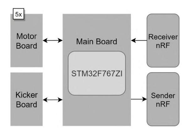
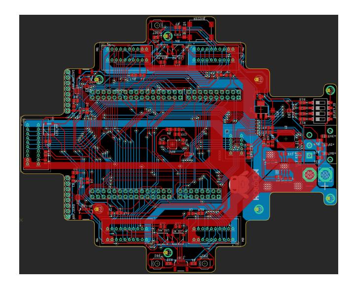
For the latest embedded system developments, we worked to improve reliability and reduce system noise, and the electronic components are the same as our last TDP [4]. The team designed a new layout of the boards, adding an EMIFxx-1005 to filter signals in communication paths, and the motor controllers are now a separate board for each motor, this increased the available area for redesigning the system boards, Figure 6. The following sub-sections are going to detail these issues, how the team solved them, and the new versions of the boards.
3.1 Main Board
With the reduction of components, we redesigned the board as the communication center of the robot electronics by interfacing our boards and radios with the STM32F767ZI, Figure 7 show the new main board layout. Studies are underway to integrate the processor core and the mainboard into a single board, to miniaturize the project.
With modularization, it was possible to add one more nRF24L01+ transceiver for telemetry. The new layout of the boards allowed us to optimize the positioning of the radios to solve a problem observed in the previous version. In this new layout, the antennas were free and away from sources of interference and noise, especially those coming from the motor supply.
3.2 Motor Board
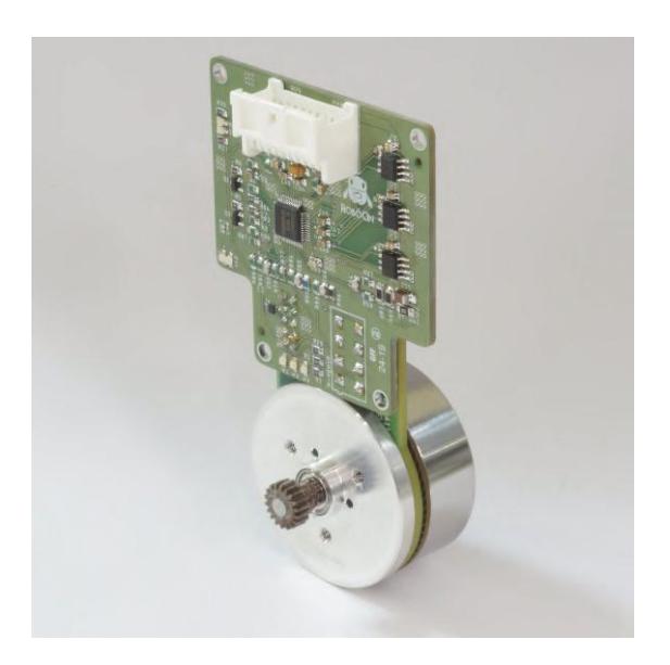
In this new layout, each motor board contains the A3930 brushless motor control driver, based on the Tigers Mannheim Team design [5], Figure 8 show the new board attached to the motor. To connect the controller and motor in a robot sub-module eases the maintenance of these components, as well as also allows the individual replacement of these sub-modules, reducing the maintenance time related to these system components.
3.3 Kicker Board
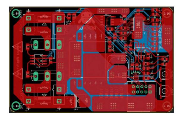
With the redesign of the Kicker board, we expect to minimize the heating present in the old version, caused by poor dimensioning of the tracks that connected the capacitors to the solenoids. Another problem observed was the presence of reverse current in the communication path between the driver gate FAN3229 and the insulated-gate bipolar transistor (IGBT) after the kick activation. This current burned the FAN, depending on the activation time set, because of this, in the new version diodes were added in these tracks, Figure 9 shows the new kicker board layout.
These changes will increase the durability of the boards. However, this diode increases the activation time of IGBT in the order of hundreds of milliseconds, so the kick always occurs with maximum force. Given the possibilities generated by the new kicking mechanism, the team is studying for solutions that best suit our needs.
3.4 Base Station
After suffering from some communication problems at RoboCup 2019, the team reviewed the whole pipeline of communication between the software and our robots. The new requirements included an interface re-connection together with higher bandwidth, capable of sending messages faster than the camera frame rate while receives robots' telemetry.
With the new embedded system developed by the team, every robot has one pair of nRF24l01 transceivers that enable duplex communication without changing the mode of the transceiver of operations, because it increases the latency of the messages. The robot communicates with a base station built on top of an ARM H743ZI2, a brand new STM development board with 400 MHz and mbed support.
The base station has two transceivers to forward packets from the computer to the robots and another one to forward the robots telemetry to the computer. That exchange of messages is made under the Ethernet protocol, chosen because it matches the upgrade requirements of the team, and also has support in the development board. The team designed the RoboCIn communication protocol to minimize bandwidth, so it uses bitwise structures of C++ and already supports 16 robots aiming at future participation in Division A.
The telemetry enabled the team to monitor and act during the game, depending on the robot's status. Information like the battery, sensor status, kicker load, and wheel speeds are received, displayed, and supports our strategy to make decisions like robot role. An essential aspect of the telemetry was the maintenance of the robots, and it speeds up the robot's check-up.
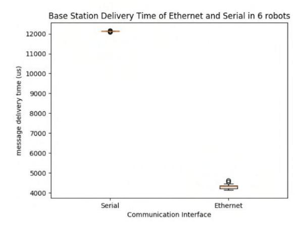
Besides all the monitoring advantages and confidence that the new communication of RoboCIn brought, a considerable decrease of latency was achieved with the use of an Ethernet interface, optimizing the transmission interval message in the software. The latency difference, shown in Figure 10, was observed in one robot when the base station was communicating with six robots. It decreases from 12.00ms in USB Serial interface to 4.33ms in the Ethernet interface optimized and with telemetry.
3.5 PID Tuning Approach
In our first year, we had some issues with how to control our Brushless DC motors properly. The robot will not follow the desired path planning if the motors don't execute the motor speeds that are requested from the software quickly. Although our first controller worked well in the competition, our performance on controlling the robot at low speeds was not adequate.
In our first year, we designed a controller using trial and error, and in our first attempts, we damaged some MOSFETs and Motor drivers. The proposed approach uses a transfer function that approximates the motor behavior using MATLAB's System Identification Toolbox [2]. This toolbox helps us to identify a function that represents the motor behavior accurately. To determine the transfer function, we need to extract samples from the real motor that can be used by the toolbox.
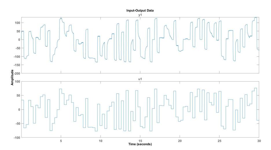
In this study, we generated 511 inputs of Multi-level Pseudo Random Signal (MPRS) within motor operation range, and we measured the motor response (in rad/s) with a sampling time of 0.002s. Figure 11 shows a part of this data from one of our motors. The input (u1) is the PWM signal sent to the motor, and the output (y1) is the motor response in rad/s read by the encoder.
The team imported the collected data onto MATLAB's System Identification Toolbox and found a discrete-time transfer function. This method is called a black-box methodology, where we derive a plant model without knowing the system behavior in advance. Using normalized root mean squared error (NRMSE), the model fits with more than 90% of data for the four motors used to validate this approach. With this transfer function, we can use the MATLAB's PID Tuner toolbox to find the PID constants that match the system requirements.
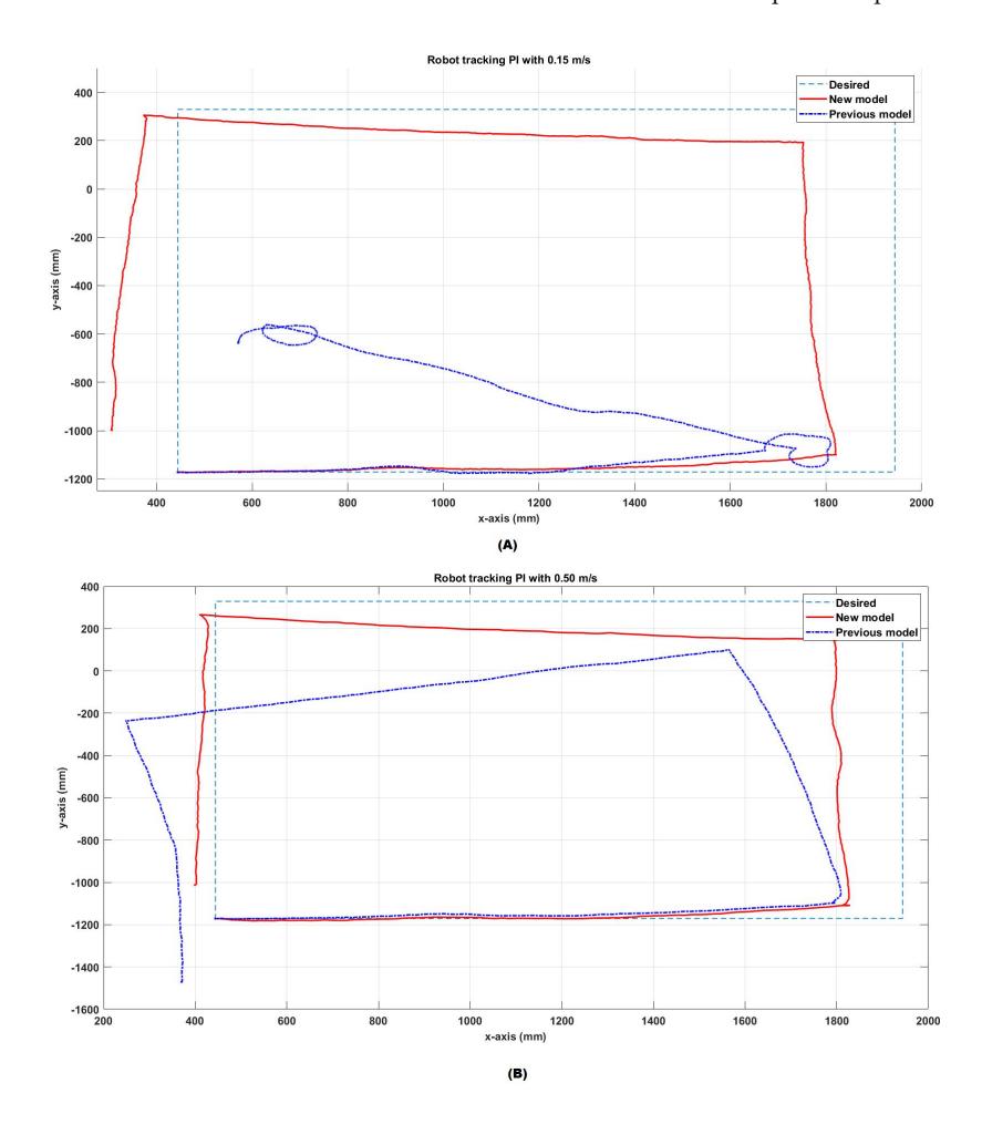
To see how it improved the motion control, the team experimented commanding the robot to perform a square of 1.5m using only the low-level PID controller. Figure 12 shows the performance of the new tuned controller and our previous controller for a speed of 0.5m/s (a) and of 0.15m/s (b). The team performed this experiment in a real-world environment.
We can see the improvements in the low-level controller at lower speeds. The team expected this improvement because the previous controller was a Proportional and Derivative algorithm (PD), which can't eliminate the steady-state error, which means that the motor will not eliminate the error between the desired and the current speed. With this approach, our team was successful in implementing a PI algorithm tuned using MATLAB's tools, and this will increase our robot's accuracy during the game, especially at lower speeds.
4 Strategy
In 2019 the team had two competitions to test and validate the core of our software infrastructure presented in our last year TDP. Therefore, for this year, the fundamentals of our software part, as the software architecture, data flow, and path planning, remain the same as the last year. The main improvements consisted of the development of a more robust and reliable user interface and a heuristic to choose the best teammate to pass the ball or to shoot on the opponent's goal.
4.1 User interface
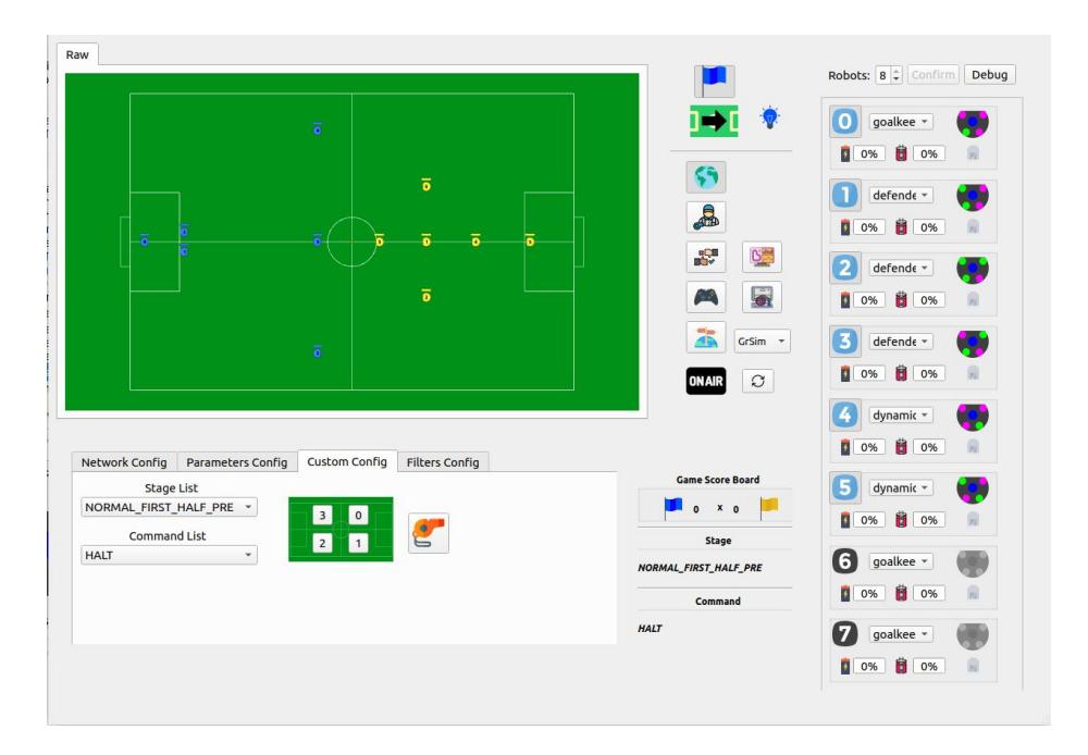
During the team first competition, RoboCup 2019, we faced some problems to test using only a part of the field and without receiving packets from the referee. Besides that, we encountered some difficulties during the game, because we could not track our robot's information, and easily choose the behavior for each robot. Therefore we developed the user interface to improve our tests and monitor the robot's information, Figure 13 shows the designed user interface.
The user interface has five main parts: the game status widget, the game visualizer, the buttons widgets, the configure tab, and the robot widgets. The game status widget shows in real-time the data received from the Referee packets and helps us to debug the communication with the Referee.
The game visualizer is an instance of the graphical client provided from the SSL Vision. In this client, it is possible to see the raw data from the SSL Vision and the data after applying some filters to reduce loss and noise from the raw data. Also, we use this visualization to draw some reference points and lines, which allow us to debug the strategy software components, path planning, pass trajectory, and team formation.
The main task of the buttons widget is to control which software component is on and which thread is running. So, it is possible to test each component separately, making it easy to find where one problem occurs. Besides, there is three more functionality in the buttons widgets: it is possible to control the reception of telemetry packets; it can open the GrSim quickly, and also it is possible to change the destination for the control packets. The control packets can be the robots, using the radio, or the GrSim using Ethernet protocol.
The robot widget allows the user to see the robot status received from telemetry and to choose tasks for each robot separately. For each robot, it is possible to follow in real-time, the battery level, how much the capacitors are loaded, and if something is blocking the IR sensor, used to detect the ball. Also, it is possible to add new information received from telemetry quickly. Besides, in the robots widget, it is possible to easily define the behavior for each robot and test different game situations.
The configuration widget has four tabs: Network Config, Parameters Config, Custom Config, and Filters Config. In the Network Config tab, it is possible to set the IP address and port used to receive and send packets. The Parameters Config tab change some parameters to make the tests easy quickly. The most crucial tab to test some specific behavior, not during game time, is the Custom Config tab, where it is possible to simulate Referee states and command and also use only a part of the field. In the tab called Filter Config, the user can choose which visualization filter use and what to draw in the game visualizer.
4.2 Shoot or Pass Heuristic
During our first year in the league, we figured out that one of the most critical skills during a SSL game is to perform an accurate pass to one of the teammates. The first step to executing this kind of play is to decide if it is better to shoot at the opponent's goal or pass the ball to a teammate with a high probability of receiving the ball. Therefore the team developed a heuristic to measure the quality of a shoot or a pass.
The shoot heuristic uses two factors to measure its quality: the distance to the opponent's goal and the clearance of the shooting line. A smaller distance to the opponent's goal increases the probability of performing a shoot as the robot with the ball is close to the opponent's goal. It decreases linearly as the robot moves away from it. The distance of every opponent robot to the shotting line defines the shot clearance. The closer the opponents are from this line, the less likely it is to shoot the opponent's goal.
The quality of a possible pass to a teammate uses two factors, the clearance of the passing line and the estimation of a shot in the opponent's goal, performed by this teammate. The likelihood of a teammate gets the pass is high as long there are not opponents blocking the passing line, and there aren't opponents closer to the teammate aimed to receive the pass. It is used the metrics from the shoot heuristic supposing that this teammate has the ball to estimate a shoot on the opponent's goal.
These calculations assign each action a real value between zero and one, and then it chooses the highest value action. Besides, there are also some small adjustments; for example, in an indirect free kick, it is not allowed to shoot on the opponent's goal, so in this case, there is no shot probability. Another safety measure is to avoid to pass to our goalkeeper or one of our defenders.
5 Conclusion
This year we presented a more stable version of our robot. Our efforts have focused on building reliable mechanics using as much 3D printed parts as we could, and we showed that it is possible to have a mechanically stable robot using 3D printed parts. On the electronic side, our focus was to correct all design errors of the first version. We separated the driver's motor circuits into different boards to avoid communication interference and redesigned the kicker board to improve routing. Also, we presented an approach for PID tuning that is generic and works with any brushless DC motors, which improved our motion control significantly and communication with telemetry and using Ethernet protocol. Furthermore, we presented our advancements in the user interface and a shoot/pass heuristic in development.
6 Acknowledgement
We would like to first thanks to our advisors and the Informatic Center - UFPE (Centro de Informática (CIn) - UFPE) for all the support and knowledge during this year of projecting and development. We also would like to thanks all the help from our sponsors: In Loco, Neurotech, Maxon Group, HSBS, In Forma, Maedler, Altium, CI Intercâmbio e Viagem, Lierre and Instituto Nacional de Tecnologia em União e Revestimento de Materiais (INTM).
References
- Immortals Team: 3D Printed Robot (2018), https://github.com/Ma-Ghasemieh/Immortals_ssl_opensource_mech
- LJUNG, L.: System identification toolbox: User's guide. MathWorks, 4th edn. (2012)
- Research, P.: Original prusa i3 mk3s kit, https://shop.prusa3d.com/en/3d-printers/180-original-prusa-i3-mk3-kit.html
- Silva, C., Martins, F., Machado, J.G., Cavalcanti, L., Sousa, R., Fernandes, R., Araújo, V., Silva, V., Barros, E., Bassani, H.F., de Mattos Neto, P.S.G., Ren, T.I.: RoboCin 2019 team description paper (2019), robocup Small Size League, Recife, Brazil, 2019
- Tigers Mannheim Team: Open Source Software and Hardware (2018), https://tigers-mannheim.de/index.php?id=65
- Tigers Mannheim Team: Open Source Software and Hardware (2019), https://tigers-mannheim.de/index.php?id=65
- Zheyuan Huang, Lingyun Chen, J.L.Y.W.Z.C.L.W.J.G.P.H., Xiong, R.: Zjunlict extended team description paper for robocup 2019 (2019), robocup Small Size League, Zhejiang Province, P.R.China, 2019