RoboJackets 2020 Team Description Paper
J. Almagro, H. Gynai, T. Jones, A. Khadse, C. Lindbeck, M. Maisonneuve, J. Neiger, R. Osawa, A. Siqueira, A. Srinivasan, K. Stachowicz, W. Stuckey, C. Wehmeyer, M. Woodward, D. Yang
Georgia Institute of Technology
https://robojackets.github.io/robocup
Abstract The RoboJackets' RoboCup SSL team was founded in 2007 and has competed every year since. This year, the team focused on improvements to the stability and consistency of the mechanical/electrical stack, as well as an overhaul of the strategy system to enable future scalability. In addition, an evaluation of the success or failure of the subsystems described in the 2019 TDP is presented for each section.
1 Introduction
This year saw a focus on platform stability and consistency. The 2019 TDP showcased many new features, including a complete overhaul of the electrical stack. However, several of these features were incomplete or underdeveloped by the time of the 2019 RoboCup competition and required additional improvements. To this end, primary goals for this year included improving the consistency of the new chipper and dribbler as well as the existing kicker, finishing revisions of electrical boards, and improving the robots' onboard motion control. On the software side, the existing strategy system was overhauled to ensure future scalability and ease-of-use.
This paper is split into sections by discipline: mechanical in section 2, electrical in section 3, and software in section 4. Each of these sections contains an evaluation section detailing the successes and failures of the work presented in the RoboJackets' 2019 TDP. In addition, a description of our open-source repositories is available in section 5.
2 Mechanical
2.1 Evaluation
There were several key improvements to make over the work presented in the team's 2019 TDP [1]. Last year's dampening dribbler system was adequate. Continued efforts to improve the mechanism's performance are described in section 2.2.
The centering roller design was not able to effectively center the ball on the dribbler. Instead, this year's robots do not require a centered ball in order to shoot properly. A test rig was designed to improve this functionality. Additionally, the beam-break ball sensor had alignment issues that caused it to be effectively disabled at competition; these issues were addressed with this year's design. The chipper design presented was acceptable and was not made a primary focus for this year, although minor revisions are presented in section 2.3.
2.2 Dribbler
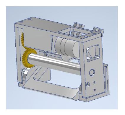
To improve the dribbler's grip on the ball, its speed has been increased. This was done by increasing the gear ratio between the motor and the dribbler shaft from 3:4 to a 4:3 ratio, for an increase in speed by a factor of 1.77. In addition to this change, the gears were moved inside the frame of the dribbler subsystem. This change increased the mouth width for better receiving of the ball. To help improve the reliability of ball detection, the location of the breakbeam sensor was shifted forward. It is securely pocketed so that it will not move around, allowing for consistent readings.
2.3 Kicker/Chipper
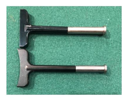
To enhance the effectiveness of the kicker and chipper, the speed of each subsystem was increased. Testing showed that the mechanisms' steel portions were not sufficiently forward in the solenoid to ensure consistent starts. The ratio of steel to aluminum was increased by lengthening each steel portion by 1cm and shortening the aluminum. This increased the acceleration on the rod from the magnetic field, resulting in a faster kick. A similar solenoid also drives our chipper subsystem, allowing us to chip much further than before. Additionally, during competition last year, our curved kicker led to inconsistent kicks when the ball was hit by the flanges of the mechanism. To fix this, it was reverted to a flat-faced kicker.
3 Electrical
3.1 Evaluation
Many of the changes described in the team's 2019 TDP [1] were successful. The microcontroller daughterboard provided us with significant performance improvements including hardware floating-point support. The implementation of the new Wi-Fi-based radio system was a huge step up in reliability over our previous DecaWave-based implementation. However, the implementation of the kicker board had several issues, which we address in section 3.3. In addition, current-sensing functionality, originally intended for motion control, was removed from our control board as it was not properly developed.
3.2 Radio
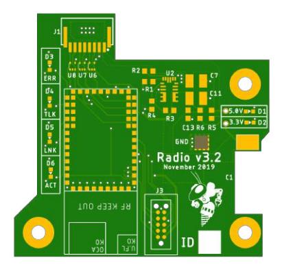
The ISM-43340 dual band Wi-Fi radio was extremely reliable throughout the 2019 competition. The team decided to scale down from two radio modules per robot to one as the redundancy was unnecessary to achieve the desired performance. The TPD2E2U06 ESD (electrostatic discharge) protection chip [2] was added to protect the board from human contact.
3.3 Kicker Board
The kicker presented in our 2019 TDP had significant routing issues that prevented its use in competition. The tolerance for parasitic and leakage inductance in the current sensing area of the flyback regulator was much lower than originally thought. As such, charging behavior was inconsistent and occasionally tripped the error heuristics in the regulator IC. The routing and placement was updated yielding greatly reduced parasitic effects, resolving these issues.
Communication with the ATmega32A has been made more reliable by adding level shifters in the form of ADUM7441CRQZ-RL7 [3] digital isolators on the SPI lines. These chips account for degraded SPI signals from the microcontroller daughterboard to the kicker board due to the length of the wire run and proximity to high frequency switching. The level shifters amplify the signal and shift between 3.3V and 5V logic. This reduces the chance that data is lost or misread during transmission. Additionally, the isolation prevents cascade failure to the rest of the system should a catastrophic failure occur.
The breakbeam system that is incorporated into the kicker board has also been modified due to unreliability in the 2019 competition. A trimmer potentiometer has been added to the transmitter so the current limiting resistance can be changed. The radiant intensity of the LED is configurable to adjust sensitivity and to account for any manufacturing variance in the LED or mechanical alignment.
3.4 Control Board
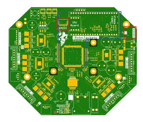
The control board had a number of improvements with the intent of creating a more stable long-term revision. The onboard inertial measurement unit was removed in favor of a connector to which custom gyroscope boards can be attached (see section 3.5). In addition, a second 3.3V line directly sourced from battery power was added, as the microcontroller board's 3.3V rail was not able to provide enough current.
The board now has six layers, which allows for better wiring and improved shielding for sensitive signals near the FPGA and the microcontroller board. Other circuit boards on the robots are now connected to the control board by ribbon cables. Mounting holes for attaching the radio board with spacers were also added around the center of the board.
3.5 IMU
To improve reliability and precision, the motion control algorithm requires a proper measurement of angular rate from an IMU (see section 4.7). The MPU-6050 IMU used in prior revisions had issues caused by the unreliability of the I2C protocol. Instead, the IMU was moved to the SPI bus. We are evaluating the ICM-42605 and the LSM9DS1 [4] for use in our system. Each of these IMUs will lie directly under the microcontroller board on a custom daughterboard. This removes some complexity from the main control board, while also allowing compatible IMU revisions without the need for additional revisions of the control board. This configuration will allow empirical confirmation of the devices' noise characteristics, as well as in-system testing with each potential IMU.
4 Software
4.1 Evaluation
The software changes presented in the team's 2019 TDP [1] had limited success. The modified multi-hypothesis extended Kalman filter for vision worked very well compared to previous years. However, there is still a need for the explicit ability to account for poor or obstructed vision: robots blocking the ball or reductions in the number of cameras. Improvements to the ball-capture system significantly improved capture performance; however, there is a need for further research into capturing within an adversary-filled environment. Finally, unforeseen problems in the electrical stack's development cycle prevented us from implementing gyroscope feedback or current sensing (for torque control) into our motion control.
4.2 Introduction to Play System Changes
The play section of the code base was overhauled to promote sustainability and modularity. Some of the problems faced in the 2019 competition were caused by a lack of diversity in play choices. Plays are also fundamentally difficult to test repeatedly, which makes it difficult to find errors and test effectiveness with particular robot positions on the field. The changes that were made this year push forward the ability to make new plays while allowing the future possibility of moving from B league (6 robots) to A league (11 robots).
4.3 Plays and Situational Analysis
Each play consists of a state machine where each state calls a combination of single and multi-robot sub-behaviors. In this way, top level strategies can be constructed from a combination of lower level strategic elements. A playbook of plays is created to run during gameplay, switching between plays based on heuristic scoring functions which act as the cost of running each play. However, these scoring functions generally have no interpretable meaning, and as a result it is very difficult to balance the scores of many different plays in a reasonable manner.
Due to challenges in balancing scores between plays, smoothly switching between plays, and difficulty in defining the scope of plays, in previous years the team defaulted to an "omni-play" paradigm. In this paradigm, a single play is used for regular gameplay, only switching to other plays for special situations like restarts and the stopped state.
Using only a single play for all gameplay situations has a detrimental effect on modularity and flexibility in developing new strategies for a number of reasons. Creating new plays is challenging because of the large variety of gameplay situations that that must be taken into consideration for a single play, causing them to be bulky and complex.
In order to combat these challenges and diversify strategies, the situation analysis system was developed. This system runs alongside the existing system and categorizes the current game state into discrete situations. These represent the aspects of the current game state that are relevant to play selection at a high level. This approach allows plays to have a defined scope, with two key benefits: first, each play has a limited scope of game states it must cover, and second, a play's cost function must only be tuned against other plays that cover the same situation. The situations have been defined in Table 1.
Table 1: Situations listed by the game conditions that trigger them
| Our side of the field | Their side of the field | Our goalzone | ||
|---|---|---|---|---|
| Our possession | clear | attack goal | goalie clear | |
| Their possession | defend goal | defend clear | N/A | |
| Contested ball | defensive pileup | offensive pileup | N/A | |
| Free ball | defensive scramble | offensive scramble | N/A | |
| Our restart | defensive kick | offensive kick | N/A | |
| Their restart | defend restart | defend restart | offensive | N/A |
| Our Penalty | N/A | penalty | N/A | |
| Their penalty | defend penalty | N/A | N/A |
The situation analysis module makes classifications based on factors such as ball possession and ball location. The field is broken down into an offensive half and defensive half. For the determination of possession, the location of the ball relative to the mouth of each robot is used along with the trajectory of the ball and a series of timers that act to provide hysteresis to the system.
It is expected that by being able to write specialized code for these common situations, robot responsiveness and effectiveness will improve.
4.4 Testbench System
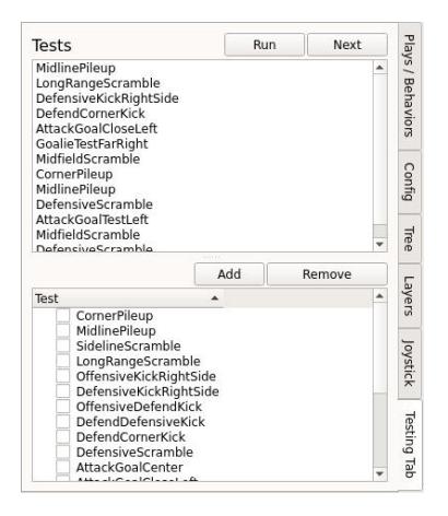
One of the main priorities this year has been to increase the robustness of the testing strategy at a number of levels. To increase the ease of testing, a simulation testing system was developed to generate repeatable scenarios to test how the logic responds. This allows us to specify a list of tests, each of which sets the positions and velocities of all of the robots and the ball. The system will then load only the desired plays and cycle through the required game states to trigger the intended behavior.
This system can be used to track progress and see the impact of code changes with detail and precision in a wide variety of gameplay scenarios. The interface for the system is depicted in Figure 5.
4.5 Formation System
The formation system improves scalability when adding additional robots and simplifies the implementation of new plays. This system creates a structured approach to dealing with additional robots who do not have an active role in the play by placing them in advantageous positions.
The idea of formations resembles real life soccer by directing the players to hold a default relative position and, should the ball approach them, allow them to make plays off the ball. This provides a structured "default" behavior for idle robots. Forwards will aggressively position to be open for passes, defenders will position defensively to cover areas, and midfielders will be a blend of the two behaviors.
The majority of the action in a RoboCup SSL match traditionally takes place close to one of the two goals, with long passes across the field. However, placing interceptors in this area can impede those passes [5]. The introduction of formations is expected to continue this trend and force more complex midfield play.
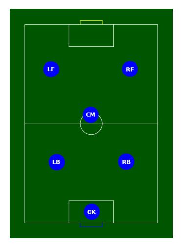
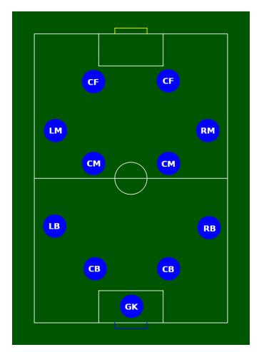
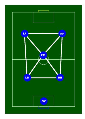
At the highest level, the formation controller decides how the formation should be structured, what type of latent behavior should be assigned to each specific position, and where the center of the formation should be. The structure specifies how many defenders, midfielders, and forwards there will be on the team and where they will be situated relative to each other. This mirrors the standard description of soccer formations using numbers, such as 2-1-2 as seen in Figure 6 or 4-4-2 as seen in Figure 7. Each position within a specified formation can be given a unique behavior allowing aggression and the default field location of each position to be tuned independently. The center of the formation will shift according to ball position such that there can be a forward pass at all times except at the very end of the field.

4.6 Role Assignment
The previous implementation of role assignment uses the Hungarian algorithm [6] to assign robots to roles in a globally optimal way. This produces significant challenges in the context of RoboCup because costs must be balanced across all roles. For example, if this is not done correctly, the robot currently dribbling the ball might swap roles with a defender. However, in reality only the robots directly interacting with the ball must be assigned optimally - the other robots have weaker requirements. The new role assignment fills the roles in tiers based on their importance. Table 2 describes these tiers and their corresponding roles, with more important roles in higher tiers.
Table 2: Roles and corresponding assignment priorities
| Tier | Role Type |
|---|---|
| 4 | Direct interaction with ball |
| 3 | Probable interaction with ball in near future |
| 2 | Unlikely interaction with ball, but part of current play |
| 1 | Formation controlled robots |
Starting at the highest tier and working down, the roles are filled with currently unused robots using the Hungarian algorithm until there are no more roles for that tier. In practice, this greatly simplifies the design of cost functions, as only similar roles are pitted against each other. For example, roles directly interacting with the ball often calculate the cost of capturing the ball. The tier system does not allow this type of cost function to be compared to the simple "closest robot to point" cost function usually found in standard move commands.
4.7 Onboard Motion Estimation and Control
In the 2019 competition, the team encountered significant issues caused by wheel slippage. In particular, when attempting to move sideways, one wheel often broke static friction, causing the robot to spin. Because the wheel itself continued to spin at the correct speed, feedback from a gyroscope is needed to account for these disturbances (see section 3.5).
This year substantial effort was directed towards improving the robots' motion control architecture. The primary goal was to move as much of the feedback control as possible onto the robots, rather than running it on the central computer. By reducing the latency in feedback loops, more accurate and precise control should be achieved.
Robot Model In [7], a generic nonlinear model for an omnidirectional wheeled mobile robot is derived. It combines a linear base model with a single nonlinear term (multiplicative with angular velocity) to encapsulate the effects of rotation on lateral motion. To find coefficients for this model, a linear regression was performed against test data.
Estimation On-board the robot, a Hybrid Extended Kalman Filter estimates world-space position and velocity. This filter takes in wheel speeds and angular rate measurements at 200Hz, and updates the estimate with vision measurements when they arrive. This allows for implementation of both accurate high-frequency measurements (from IMU and encoders) as well as low-frequency measurements (from vision) to provide one high-quality estimate.
The state (x), odometry measurements ($y^o$), and vision measurements passed from the host computer ($y^v$) are as follows:
$$\mathbf{x} = (x , y , \theta , v_x , v_y , \omega)$$
$$\mathbf{y}_o = (v_1 , v_2 , v_3 , v_4 , v_g)$$
$$\mathbf{y}_v = (x_v , y_v , \theta_v)$$
The prediction equation of the Kalman filter is then standard. However, instead of a single update step, there are two separate update equations: one to run at 200Hz for on-board sensors and one in lockstep with the reception of vision data.
The below equations represent the combined predict-update cycle of the Extended Hybrid Kalman Filter. f(x, u) represents dynamics as derived in [7] with Jacobian F, h(x) is a linear measurement model converting velocities to encoder and gyroscope measurements with Jacobian H, and g(x) is a simple measurement model with Jacobian G extracting only the position states (and discarding velocity), representing the vision measurement. The predict-update cycle based on odometry measurements follows the standard equations:
$$\mathbf{x}{k+1|k} = f(\mathbf{x}{k+1}, u_k)$$
$$S_{k+1|k} = F_{k+1} S_{k|k} F^T + Q$$
$$K_{k+1} = S_{k+1|k} H^T (H S_{k+1|k} H^T + R_o)^{-1}$$
$$\mathbf{x}{k+1|k+1} = \mathbf{x}{k+1|k} + K_{k+1} (\mathbf{y} - h(x_{k+1|k}))$$
$$S_{k+1|k+1} = (I - K_{k+1} H) S_{k+1|k}$$
When a vision update is required, the following update rule is applied (with x' and S' representing in-place updates of x and S, respectively). Note that vision packets may come at any time - between two regular updates, there may be one or zero vision updates.
$$L_k = S_{k|k}G^T (GS_{k|k}G^T + R_v)^{-1}$$
$$\mathbf{x}'{k|k} = \mathbf{x}{k|k} + L_k(\mathbf{y}v - g(x{k|k}))$$
$$S'{k|k} = (I - L_kG)S{k|k}$$
Control With a clean position/velocity estimate, the robot's internal feedback loop can be run on both position and velocity. An LQR-based feedback controller with feedforward and feedback linearization was chosen to account for the nonlinear terms as described above.
First, the current setpoint of position, velocity, and acceleration is sent from the central computer to the robot. Then, a linear quadratic regulator (derived by linearizing the system around $\dot{\theta} = 0$) calculates desired feedback acceleration. This is added to the feedforward acceleration (from the setpoint) to produce an acceleration in body-space, which is run through the inverse dynamics of the system to calculate the required wheel voltages, in a manner similar to feedback linearization [8].
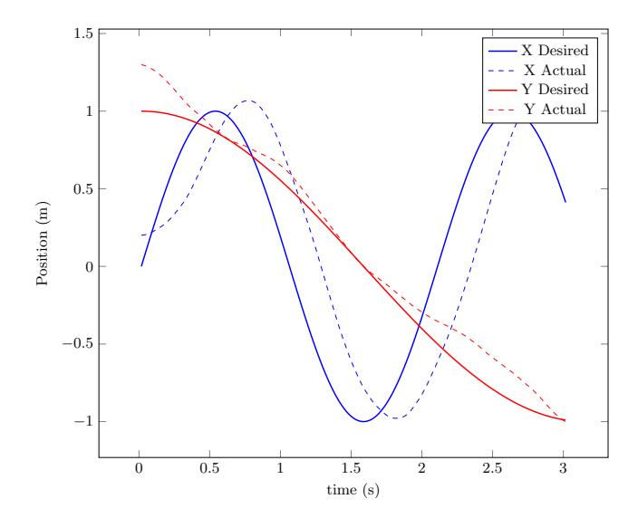
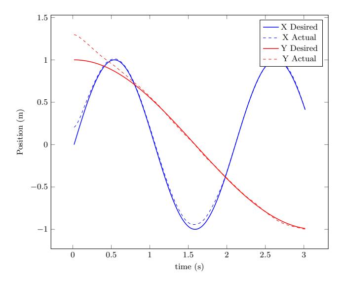
Figure 9 and Figure 10 show a simulation of controlling the robot with a simple linear feedback controller and no feedforward compared to the full feedback-linearized controller with feedforward acceleration. A modeling error of 20% reduced motor output power compared to the modeled value is intentionally injected into the system to test robustness. The improved controller exhibits significantly better tracking performance.
5 Open Source
RoboJackets continues to open source our mechanical platform in addition to PCBs, firmware, and software systems. This work is available at https://robojackets.github.io/robocup.
6 Acknowledgements
We would like to acknowledge Matt White, Evan Peterson, Tanner Beard, Ethan Gordon, Stella Fournier, Manzano Akhtar, and Terence Lui for their technical contributions to the work discussed in this paper.
References
- RoboJackets RoboCup SSL Team. RoboJackets 2019 Team Description Paper. Technical report, Georgia Institute of Technology, 2019.
- Texas Instruments. TPD2E2U06 dual-channel high-speed ESD protection device, 2019.
- Analog Devices Inc. 1 kV RMS quad-channel digital isolators, 2015.
- Kris Winer. Affordable 9 DoF Sensor Fusion, 2019.
- Theresa Engelhardt, Tobias Heineken, Tobias Kuehn, Jeldrik Lindner, Mike Schmidt, Felix Schofer, Christian Seifert, Michael Stadler, Lukas Wegmann, and Andreas Wendler. ER-Force 2019 extended team discription paper, 2019.
- H. W. Kuhn. The hungarian method for the assignment problem. Naval Research Logistics Quarterly, 2(1-2):83–97, 1955.
- Md. Abdullah Al Mamun, Mohammad Tariq Nasir, and Ahmad Khayyat. Embedded system for motion control of an omnidirectional mobile robot. IEEE Access, 6:6722–6739, 2018.
- A. Megretski. Lecture notes in dynamics of nonlinear systems, lecture 13: Feedback linearization, Fall 2003.