SRC Team Description Paper for RoboCup 2020
Jiawei Lin, Jie Chen, Baiji Chen, Kaichong Lei, Zikang Shi, Jiaping He, Zhengwei Qin, Jiaxuan Xie, Jingwei Xu, Zhaocong Liu, Ruiqing Ge, Li Hao
Student Innovation Center, Shanghai Jiao Tong University, P.R.China
Abstract This paper describes the mechanical, electronic and overall technical framework designs developed by the SRC Team from SJTU in order to join the RoboCup 2020. The overall concepts are in agreement with the rules of Small Size League 2020. This is the second time SRC participates in the RoboCup.
Keywords: transmitter · boost converter · multi-robot system
1 Introduction
Since 2006, Shanghai Jiao Tong University has started to participate in RoboCup mid-sized robot soccer competitions, and has been one of the earliest universities in China to participate in RoboCup. The SRC team, which focuses on the RoboCup football robot small size league competition, was established in 2015. Since its establishment, it has become one of the most popular student organizations in SJTU. Our team members ranges from different grades, from undergraduates to doctoral students, who have a strong interest in robotics competitions through the recruitment of the entire university. We use our spare time to come to the Student Innovation Center to learn ,training. Through the joint efforts of players and teachers, the club has achieved outstanding results in previous competitions. In July 2017, at the World-wide RoboCup 2017 Nagoya, Japan, it won small size league soccer robot World Cup champion. For RoboCup of China level, we also won championship in the national contest for consecutive years from 2018 to 2019.
In what follows we plan to introduce what we have achived in preparing for RoboCup 2020,ranging from mechanics, electronics to overall technical framework.
2 Mechanics
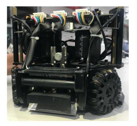
Our hardware is unchanged since 2017 which is shown in Fig 1. The major problem of our previous mechanical design is the horizontal distance of our chipping, the average chipping distance is about 1.8m.
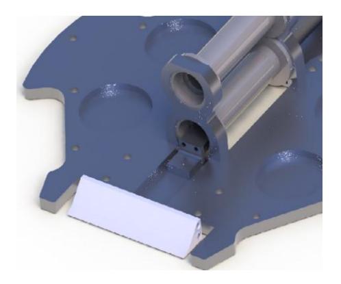
The chip kick module of our robot is to use connected rods structure which ZJUNlict[1] proved that its efficiency is much lower than directly impacting structure which is shown in Fig 2.
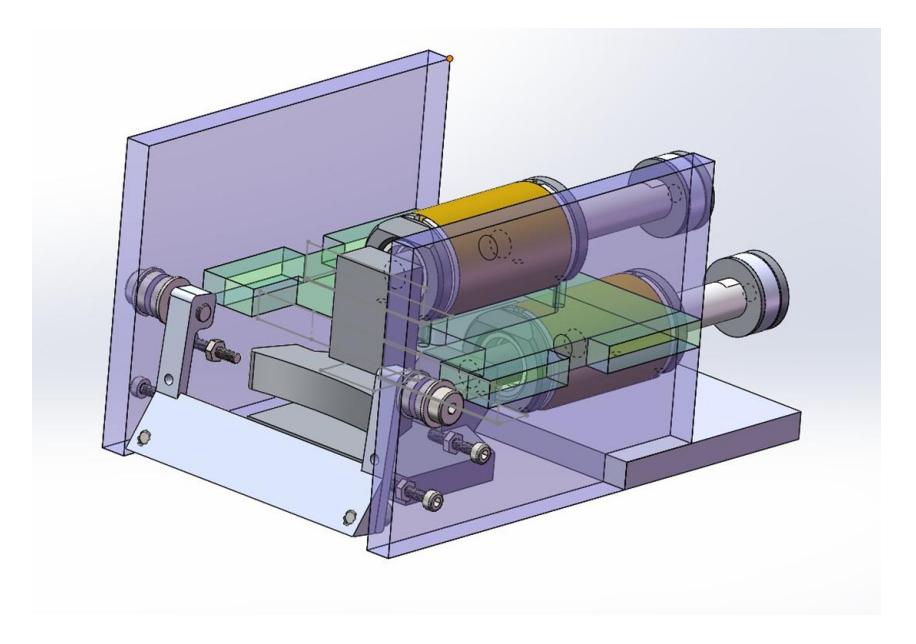
We have replaced the inefficient connected rods structure with directly impacting structure. To initiate, we designed a prototype of kick and chip module which is shown in Fig 3. The prototype test shows that the new module has a significant improvement compared with our previous robot, which will be detailed in the next section.
3 Electronics
This section describes the electronic systems developed for the robot.
3.1 Powerboard
Structure introduction
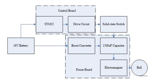
The kicking system is shown in the following Fig 4.
The main function of power board is to convert 16V of the battery to higher voltage, and receive the control signal from the control board based on STM32, in order to provide energy for the electromagnet to kick the ball. The power board circuit is mainly composed of a BOOST converter. The input is a 16V battery. The output voltage is high enough to drive the electromagnet to kick the ball. The UC3843 is used to control the BOOST converter.
Improvement
In previous years, the output voltage of our power board is about 138V . Under this condition, the robot can chip the ball up to 1.8m. In order to chip further, the capacitors of BOOST converter should store more energy for the electromagnet. According to the formula
$$e = \frac{CU^2}{2}$$
where C, U represents the capacitance and voltage respectively, so the energy can be increased either by raising the capacitance or voltage.
Higher capacitance means that much more space are required for bigger capacitor. Since the space inside the robot is limited, our object is to increase the output voltage. We increased the output voltage from 138V to 214V . The output of BOOST converter is connected to the electromagnet through the IGBT. Once the kicking signal from the control board arrives, the IGBT will be conducted on, and then the energy of capacitors will be consumed by the electromagnet to chip the ball. In order to tolerate high voltage and large current when the energy is being consumed, the SGL160N60UFDTU is used, which can work under the condition of 600V, 160A.
Test
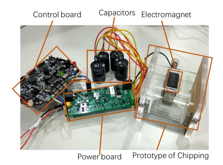
We built the test system to test our new power board, which is shown in the following Fig 5.
The test results show that the BOOST converter can generate 214V voltage (55% higher than the previous board) and the maximum chip distance of the new system is about 4m (122% longer than the previous 1.8 meters), which is a great improvement. So far, our test prototype has been working steadily. Now we are transplanting new system to our robots. This work will be finished soon and applied in the coming competition.
3.2 Network transmitter
Network transmitter is responsible for the communication between computer and robots. The framework squared in the Fig 6 is the network transmitter.
We implement the transmitter function using two different devices, One for sending and the other one for receiving:
- The sending device receives the command packet sent from the computer's Ethernet port, reads and parses the content of the Ethernet packets, then sends it to the robot on the field with the nRF241 chip.
- The receiving device receives the status information sent by the robot on the field, reads and parses the contents of the Ethernet packet, and then sends it to the computer through the network port.

Hardware
nRF24L01
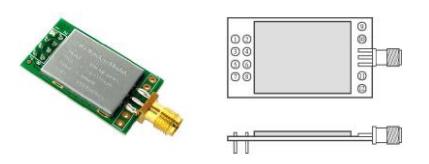
The nRF24L01+ is a single chip 2.4GHz transceiver with an embedded baseband protocol engine (Enhanced ShockBurstTM ), suitable for ultra low power wireless applications. It is designed for operation in the worldwide ISM frequency band at 2.400 − 2.4835GHz. We use E01-ML01DP5 (shown in Fig 7) module provided by Ebyte Co., Ltd, which integrates nRF24L01,PA(Power Amplifier) and LNA(Low Noise Amplifier). This module feathers with large transmit power, good receiving sensitivity and anti-interference ability.
DP83848C
The DP83848C is a high speed and robust device meets IEEE802.3 standards. It can be used as an ethernet physical layer transceiver. It offers MII MII or RMII interface.
Software
Development environment
STM32F407ZE is used as the controller. We use the STM32CubeMX tool to generate most of the system's hardware driver code, including SYSTIC, RCC, GPIO, ETH, UART and LWIP. On this basis, we export the code to Keil uVision5 for further development and debugging.
Code framework
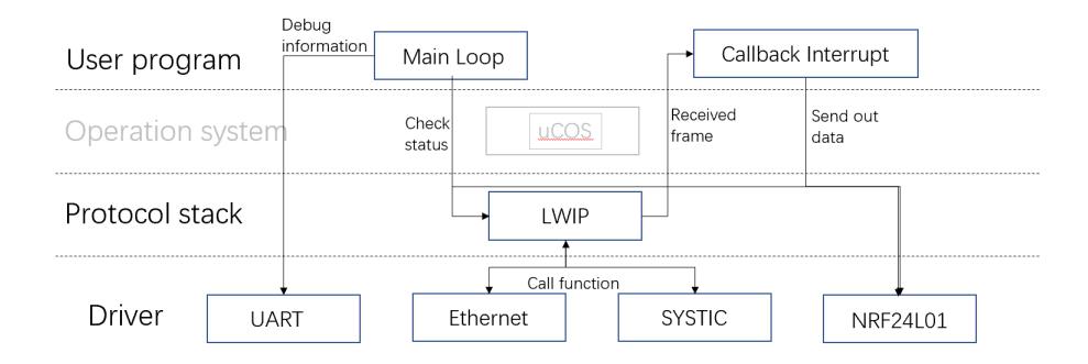
Apart from drivers generated from STM32CubeMX, we also write the driver of NPF24L01. We use LWIP, a small independent implementation of the TCP/IP protocol suite. LWIP provides enough interfaces, so we can simply call functions from user layer and don't need to consider the details of UDP protocol. We use the hierarchical code architecture shown in Fig 8.
PCB board
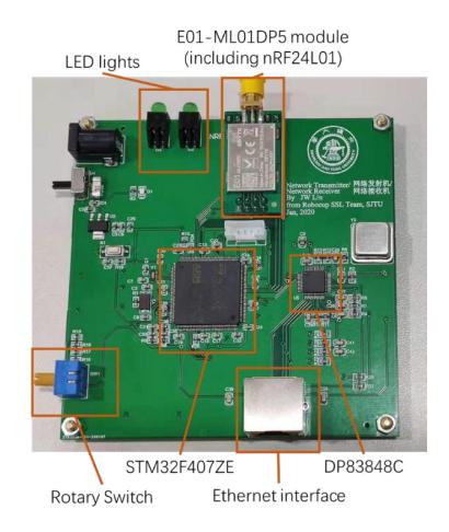
We designed a PCB board with all the parts as shown in Fig 9. Besides the E01-ML01DP5, DP83848C and STM32F407ZE which are previously mentioned, we also included some friendly designs in the board. For example, the blue rotary switch is used to adjust the RF frequency and two LED lights on the upper left side are used to indicate the communication status.
4 Overall technical/software framework
Our team builds a complete processing system which is capable of receiving information, processing information, making decisions and executing. This system is the brain and center that supports our game. It can be used in real robot races and simulation races and tests. In both modes, the processing flow of this system is roughly the same, and the performance is equally excellent. Now let us introduce the workflow of our system in two modes.
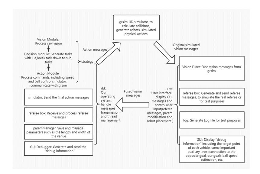
In simulation mode, we use a simulator called grsim[3]. It's a 3D simulator, which can generate robots' simulated physical actions and simulated vision messages, and calculate collisions. After generating information about the game (such as simulated vision messages, state of movement), it sends those to an interactive software called owl. This software can display the simulation game progress and the on-court conditions, while it can also integrate several functional plugins listed as follows:
- The first is a plug-in called Vision Fuser, which is used to process and fuse the original vision messages transmitted, including noise reduction processing, filtering, etc.
- The second plug-in is the referee box, which can replace referees in real matches and issue referee instructions for test purposes.
- The third plugin is log, which can generate User Log Files and record vision messages' processing.
- The last plugin is called GUI to display "debug information", including the target point of each robot, some important auxiliary lines (connection to the opposite goal from our goal), value of ball speed, etc. This information can help us better judge what is happening on the field.
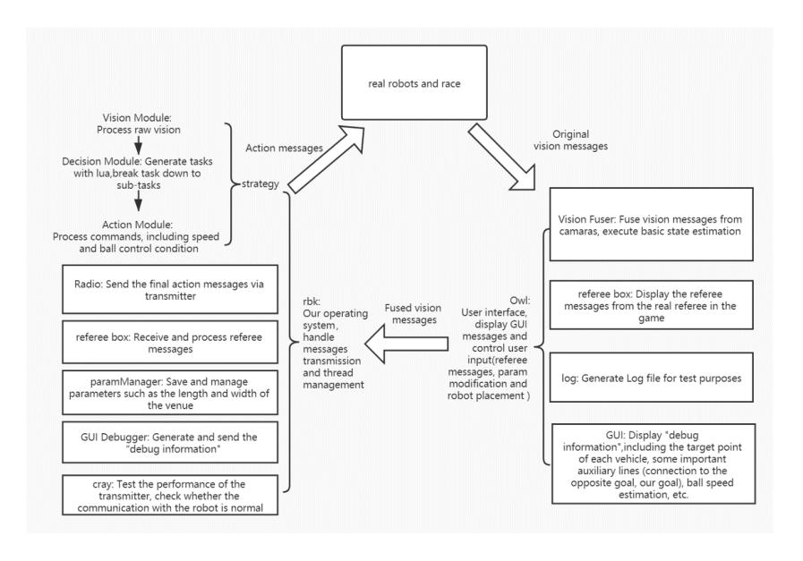
After processing by Vision Fuser, the system will send fused vision messages to our calculating and operating system called rbk. This system can make decisions based on the data received and send instructions for the next steps. In simulation mode, these action instructions will be sent to grsim for further simulated actions. Specifically, these tasks are completed by the following modules: Vision Module, Decision Module, and Action Module. In addition, rbk also integrates many other plug-ins. Their composition and functions are explained in the following Fig 10.
There is not much difference between the processing flow of the real game mode and the simulation mode, the specific differences are reflected in the following aspects:
- First of all, there is no grsim any more, vision messages is generated by the camera on the field and sent to owl; At the same time, the action instructions made by the rbk system are no longer sent to grsim, but are sent to each robot by wireless communication using a transmitter via a new plugin called Radio.
- Secondly, in the real game mode, the referee box plugin in owl can only display the instructions of the real referee, and can no longer issue the referee instructions by itself.
- Thirdly, in the real game mode, the rbk system will enable a new plugin called cray. This plug-in is used to test the performance of the transmitter, and to check whether the communication with the robot is normal.
5 Conclusion
In the above sections we have in detail clarify our efforts in building a cooperative multi-robot system, including mechanical part, electronic part and overall software framework. We plan to refine and polish our algorithms in order to realize more intelligent and reative control, and these objectives is expected to be finished by the formal contest.
References
- Lisen Jin, Lingyun Chen, Xiaoxing Chen, Yachun Li, Weijian Hu and Rong Xiong, ZJUNlict Extended Team Description Paper for RoboCup 2016. In RoboCup 2016.
- DP83848C/I/VYB/YB PHYTER QFP Single Port 10/100 Mb/s Ethernet Physical Layer Transceiver, http://www.ti.com/cn/lit/ds/symlink/dp83848yb.pdf.
- https://github.com/RoboCup-SSL/grSim.
- Monajjemi, Valiallah, Ali Koochakzadeh, and Saeed Shiry Ghidary. "grsim–robocup small size robot soccer simulator." Robot Soccer World Cup. Springer, Berlin, Heidelberg, 2011.