Sysmic Robotics Team Description for RoboCup 2020
Pablo Reyes, Maximiliano Aubel, Pablo Yañez, Nicolas Hernandez, Ricardo Alfaro, Daniel Torres
Universidad Técnica Federico Santa María, Valparaíso, Chile
Abstract This paper presents an overview of the design of the third generation of robots of the Sysmic Robotics team. In particular, the changes made since the 2019 RoboCup application in Sydney are detailed, such as the structural redesign of the robot, a damping mechanism in the dribbler, changes in the hardware design, communication system and the approach to programming the robot firmware.
1 Introduction
Sysmic, formerly AIS, is a team of students from the Technical University Federico Santa María. The team first attended the Small Size League (SSL) in 2018 in Montreal, obtaining a sixth place in Division B and now intends to participate in the RoboCup 2020, Bordeaux. An overview of the changes made since our last participation is presented in the RoboCup 2019 application, Sydney and will be appropriately mentioned according to the case.
Section 2 presents the redesign of the mechanical structure of the robot, the new design of the dribbler that incorporates an impact absorption mechanism and changes in the drivetrain, highlighting the redistribution of the internal components that allow the height reduction and center of gravity, which translates into greater stability. Section 3 describes the changes introduced in the software area such as the compatibility of the new communication system and the future work involved in programming the client software from scratch. Section 4 presents the changes made to the hardware concerning the version used in the RoboCup 2018, including the change of processing architecture to ARM, the wireless communication system to nRF24L01+, the incorporation of encoders to the motors and the approach adopted in the firmware. The study of the power consumption of our robot is shown at the end of this section, to choose more suitable battery models for future versions.
2.1 General structure
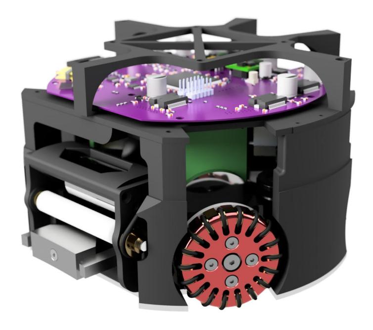
For this new version, the height was reduced to 13.5 [cm], considerably lowering the center of mass of the robot. Also, our previous design considered an 18 [cm] diameter PVC tube as the case that, due to its rigidity, transfers much of the impacts it experiences to the internal parts. Currently, the case is made of hard cardboard because it only has to protect the upper section of the robot that receives very few impacts, but it is evaluated to be made of carbon fiber.
In the new design, the structure is responsible for receiving the impacts of collisions with other robots or the shooting of the ball. It is manufactured with 3D printing using PLA filament, the plastic parts are joined to two 3 [mm] alucobond discs completing the structure of the robot. In the future, 3D prints will be made with polycarbonate or nylon filament, to achieve greater resistance and flexibility to the impacts received, in case the PLA fails to meet the requirements of the competition. Fig. 1 shows the current design of the robot structure, without the case.
2.2 Dribbler
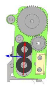
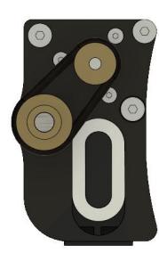
Former dribbler design has the null damping action problem: when the ball collided with the roller at a high speed, it would bounce of the roller. The new design seeks to solve this problem based on the model proposed by Tigers Mannheim team, which has two rings made of a compressible material on each side of the Dribbler's structure. This allows the whole system to move (two degrees of freedom: upwards and inwards) when in contact with the ball. Our proposed changes point to the simplification of the design and manufacturing process, ensuring that it fits with the structure of the robot (see Fig. 2). The rings on the sides (black rings in Fig. 2a) would be replaced by a oval-shaped ring of silicone, the structure of the dribbler would be made of plastic additive manufacturing (PLA with a FDM 3D printer), the gears which transfer the motion from the motor to the roller was replaced with two brass pulleys and an O'ring. The roller is placed at a height of 38 [mm] over the ground, with a diameter of 11 [mm], this means that the ball coverage is not more than 13% of the area of the ball when viewed from above.
2.3 Drivetrain
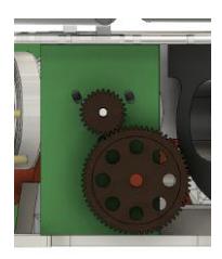
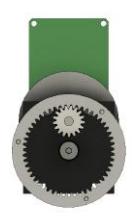
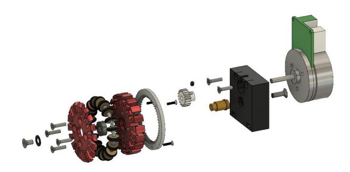
The previous drivetrain design is replaced by an internal gear system with a reduction of 51:17 and which centers the system on the motor shaft, as shown in Fig. 3b. This configuration allows us to bring the wheels closer to the base, which grants more space to the interior of the robot, distributing its internal components more efficiently, with the reduction of its height as proof of this. The gears are manufactured with hardened SAE45 steel to withstand the speed and torque generated by a 50 [W] power motor. The modules of each wheel are identical to each other, which facilitates repairs, modifications, and maintenance during the competition.
The outer diameter of the wheel is reduced from 55 [mm] to 50 [mm], matching the inner gear. To obtain smoother rotations the number of small wheels increased from 15 to 18 concerning the former design, which means a smaller separation between them when the robot is touching the ground. Due these changes the axis of the main wheels is at a distance of 54.5 [mm] to the floor when one of its small wheels is making contact with it, and 53.66 [mm] when two wheels are in contact, versus the 59.5 [mm] and 58.18 [mm] of the former version. In this way, it is estimated that the vertical oscillation of the robot goes from 1.32 [mm] to 0.84 [mm], which is directly reflected in the displacement made by the robot. In order to quantify the changes, we are currently designing a way to measure the impact of vertical vibration caused by this separation in the rest of the systems and movement.
3 Software
For the future work, the development of the new software is crucial for a good performance of all aspects since being the team's own will allow better adaptability to our robot model. The team is working on the development of a new software client from scratch. The current development involves UI, set of plays and selection of them. Also, the compatibility of the system with the vision software is being checked using grsim and recently in real robots, such as the calculation of trajectories and velocity vectors that are commanded to robots in the field.
A modified version of the RoboJackets team software has been used so far by our team. Recently a base station has been designed, composed of an STM32F767 microcontroller and an nRF24L01+ that communicates with the centralized system using USB Full Speed protocol at a rate of 12Mbps. A test client developed sends commands from a joystick connected to the computer and allows movement tests on one robot. The base station allows bidirectional communication and therefore it is possible to monitor internal variables of the robots. The base station was adapted too for RoboJackets software and later it is being incorporated into the new software of the team.
4 Hardware
For this version of the robot, the architecture of the microcontroller (MCU) is changed to centralize the computing capacity in only one unit, which incorporates the transmission of high-speed data packets, speed control over the motors, measurement from sensors and execution of game actions. As a consequence, the communication system is renewed and the number of sensors arranged throughout the system is increased. The table 1 shows a general comparison of the components of the 2018 generation of the robot and the current version 2020. Some of the hardware such as accelerometers and gyroscopes are being studied and validated, and therefore it is considered future work to present.
Table 1: Summary of main changes from former robot generation.
| Robot generation | 2018 | 2020 |
|---|---|---|
| Microcontroller | PIC32MX440F256H x5 STM32F767BI6 | - |
| Drive motors | Maxon EC-45 30W | Maxon EC-45 50W |
| Encoder | Hall sensors only | Maxon MILE 2048 CPT |
| Dribbler motor | Maxon EC16 30W | Maxon EC22 25W with Hall sensors |
| Communication module | APC220 433[MHz] | NRF24L01+ 2.4[GHz] |
| Dimension | 18 cm diam x 15 cm | 18 cm diam x 13.5 cm |
| Gear reduction | 1:2 | 1:3 |
| Wheel diameter | 55 mm | 50 mm |
| Small Wheel per Drive train 15 | - | 18 |
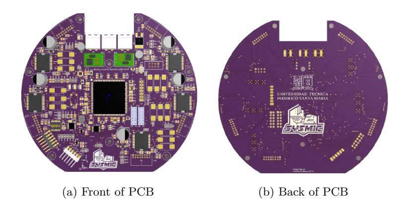
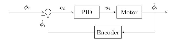
Previous architecture was composed of five PIC32MX440F256H MCU's, one of them receiving control packages from the centralized game system. Subsequently, the information is decoded to obtain a speed vector and orders regarding the kicking and driving of the dribbler. The remaining MCU's apply PID control over each of the drive motors, based on a reference calculated by the central microcontroller using the kinematic model of the robot. It is delivered in the form of analog voltage using a digital-analog converter (DAC) MAX5814. For this new version, PIC32 MCU's were replaced by a single high-performance STM32F767BI6 operating at 216 [MHz]. In this case, this MCU is capable of performing the same tasks that multiple MCU's PIC32 architecture carried out in a shorter time. Quantitative comparisons are presented in the next section. Fig. 5 shows a render of the new PCB with some of the components on the surface.
4.1 Firmware and communication
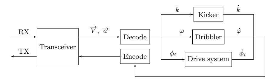
In the firmware programming, new considerations were taken for handling control instructions from the centralized system, due to the high calculation speeds and interaction with MCU modules on each task that in the previous version translated into bottlenecks because of the high dynamism of the matches.
As indicated in the previous section, the APC220 transceiver module is changed to nRF24L01+ of Nordic Semiconductors. The transmission rate of this device is 2Mbps, while the MCU communicates with the device by SPI at a rate of 8Mbps. Time comparisons of the sending and processing control instructions are shown in table 2 and denote a performance increase of around 82 times in the total transaction. Additionaly, a new communication protocol is designed by reducing the size of instruction packets from 60 to 24 bytes in total (4 bytes each robot). Table 3 shows the structure detail of instruction per robot. This protocol is based on a pruned version of the protocol created by ZJUNlict team, current champion of the SSL league, division A.
Table 2: Time differences between robot generations
| Robot generation | 2018 | 2020 |
|---|---|---|
| Module | APC220 | nRF24L01+ |
| Data rate with device | 19200 (UART baud rate) 8Mbps (SPI) | - |
| Air data rate | 19200 bauds per second | 2Mbps |
| Reception time | 38.6 [ms] | 68.5 [us] |
| Complete packet transfer and decoding 38.81 [ms] | - | 474.5 [us] |
| PID frequency | 16 [Hz] | 1 [KHz] |
| Speed measure resolution | 18 CPR | 2048 CPR |
| Execution time | 590.76 [us] | 442[us] |
Table 3: Communication protocol
| bit byte | 7 | 6 | 5 | 4 | 3 | 2 | 1 | 0 |
|---|---|---|---|---|---|---|---|---|
| 0 | - | Robot ID | - | Dribbler strength | - | Shot | CB | - |
| 1 | ± | Speed vx | - | - | - | - | - | - |
| 2 | ± | Speed vy | - | - | - | - | - | - |
| 3 | ± | Speed vθ | - | - | - | - | - | - |
Once the information has been decoded, to translate it into motion it is necessary to apply some coordination strategy between the components, to ensure integrity in the execution of control loops and communication. Because in practice the centralized system will send data packets with a frequency of 60 [Hz], the PID must be able to operate at a high speed and therefore high sampling rate and high resolution speed sensing is needed. The calculation of speeds by motor and setting analog references to their controllers by DAC reaches an approximate time of 170 [μs] total, which allows to apply the control loops for each of the motors with a frequency of 1 [KHz]. Table 2 shows quantitative comparisons with respect to the previous version of the robot.
Firmware coding is done using FreeRTOS, an operating system kernel developed to be used in MCU's and offering a large section of OS features, such as tasks scheduling and assignment of priorities, queues, semaphores, mutexes, among others. In this way it is possible to set the period of operation of the PID exactly and the detection of packets with fixed time. Although, it is possible to use different options for these tasks such as timers, this option allows the scalability of the system much more simple and modular.
4.2 Power consumption
Various tests were performed to find the relationship between the YPG 22.2V 1500mAh 70C battery currently used by our robots and the actual consumption once they are in the field. First, the behavior of the internal resistance of the battery is studied when the average current consumption increases, which response to
$$R_r = 0.0571I - 0.0506[\Omega]$$
from 506[mA] and which also considers the wiring that precedes the PCB. Fig. 8 shows the real increase in R_r and that implies a maximum decrease of approximately 0.25 [V] in the battery output.
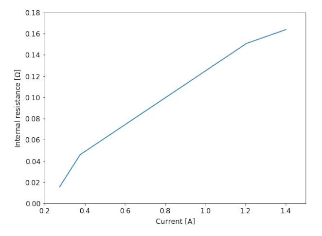
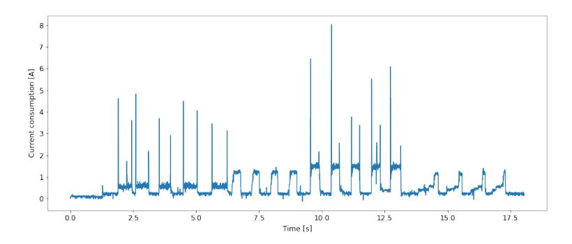
Table 4: Average power and current consumption for PCB, motors and dribbler
| State | Power consumption | Current |
|---|---|---|
| Circuit ON | 3.5 [W] | 160 [mA] |
| Motor with no load | 1.498 [W] | 66.435 [mA] |
| Motor with load | 23.463 [W] | 1050.359 [mA] |
| Dribbler without load | 4.346 [W] | 192.843 [mA] |
| Dribbler with load | 4.99 [W] | 222.787 [mA] |
Also, table 1 shows average power and current consumption for the energized PCB board and motor and dribbler performance in various circumstances. It is concluded about the battery in use from these data and those already mentioned that:
- The energized robot without movement has a maximum autonomy of approximately 9 hours and 22 minutes.
- The energized robot, in the field, at maximum speed with ball in dribbler and charging capacitors to kick the ball, implies a minimum autonomy of 1 hour and 2 minutes. Considering repetitive peaks of current at 1.784 [A] average that last around 5 [ms] approximately, with a frequency of 49 peaks per second measured in a test of the robot in normal operation for half an hour, an average consumption of 437.08 [mA] is obtained, which reduces the battery life to 47 minutes approximately.
- The mechanical weight of the robot on the wheels generates an expense of 21,965 [W], equivalent to 983.924 [mA] reducing the battery life to 39 minutes. This was measured with the robot at maximum performance suspended in the air with the motors without any friction surface more than the weight of the wheel structure itself, and then in the field.
- Contact with the official ball generates an expense of 0.644 [W].
The measured energy consumption allows us to verify that the batteries used are sufficient for 15 minutes of autonomy. However, since the robot has no current peaks greater than 10 [A], it is possible to choose a 15C battery of discharge current. With this data, it is proposed to use a boost topology that raises the required 22.2 [V] by changing the battery to a 500 mAh and 14.4V 20C. The value of the multiple C rises since the current demanded by the booster is 1 [A] maximum, which increases proportionally as the robot consumes more energy. The booster consumes 1 [A] when the robot demands about 1.4 [A] which is its maximum average consumption without considering current peaks.
References
- Andre Ryll, Mark Geiger, C.C.N.O.: Tigers mannheim extended team description for robocup 2018 (2018)
- Tomás Rodenas, e.a.: Ais robocup team description for robocup 2018 (2018)
- Tomás Rodenas, e.a.: Sysmic robotics team description for robocup 2019 (2019)
- Zheyuan Huang, e.a.: Zjunlict extended team description for robocup 2019 (2019)