TIGERs Mannheim
Andre Ryll, Sabolc Jut
Department of Information Technology Baden-Württemberg Cooperative State University, Coblitzallee 1-9, 68163 Mannheim, Germany
Abstract This paper presents details of the hardware systems of TIGERs Mannheim, a Small Size League (SSL) team intending to participate in RoboCup 2020 in Bordeaux, France. This year, the ETDP will focus on hardware design for SSL-compatible robots. Weaknesses of previous generations are outlined and changes to mitigate them are discussed in detail. Furthermore, our software implementation of the on-board camera system, used to win the technical challenge 2019, is outlined.
1 Introducing Robot Generation v2020
The v2020 generation presents our fth iteration of robots for the RoboCup Small Size League. A CAD rendering of v2020 is shown in gure 1. With 10 years of experience in designing such robots many mistakes were made and many lessons learned. In this paper, we focus on the previous generation (v2019), its strength and weaknesses, and how they are mitigated. The outcome of all xes is a major overhaul of the powertrain, the dribbler, and kicker. Most of the work went into the powertrain to ensure robust and smooth operation in a competitive environment. More details on the powertrain can be found in section 2.1. The specications for v2019 and v2020 can be found in table 1. The most prominent change can be seen on the wheel size and powertrain. A comparison of the older v2016 generation with v2019 exists in our previous year TDP [1].
While mechanics have experienced a large update, electronics remain mostly unchanged from v2019 to v2020. They have proven to work well and reliably. The details of the dierent boards, their purpose, and interconnections are outlined in section 3.
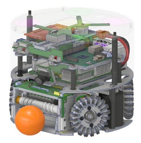
Table 1: Robot Specications
| Robot version | v2019 | v2020 |
|---|---|---|
| Dimension | Ø178 x 146mm | Ø178 x 148mm |
| Total weight | 2.5kg | 2.62kg |
| Max. ball coverage | 19.3% | 19.8% |
| Driving motors | Nanotec DF45L024048-A2, 65W1 | |
| Gear | 30 : 50 | none |
| Gear type | External Spur | Direct Drive |
| Wheel diameter | 33mm | 62mm |
| Encoder | RLS RLC2HD, 36864ppr [2] | iC-PX2604, 23040ppr [3] |
| Dribbling motor | Maxon EXC Speed 13L HP | Moons ECU22048H18, 55W |
| Dribbling gear | 12 : 32 + 14 : 18 | 1 : 1 : 1 |
| ØDribbling bar | 12mm | 11.5mm |
| Kicker charge | 4400µF @ 230V (116.38J) | 3600µF @ 240V (103.68J) |
| Chip kick distance | approx. 3m | approx. 3.6m |
| Straight kick speed | max. 8.5m/s | max. 8.5m/s |
| Microcontroller | STM32H743 [4] | |
| Sensors | Encoders, Gyroscope, Accelerometer, Compass, Camera | |
| Communication link | Semtech SX1280 + FEM @1.3MBit/s, 2.300 - 2.555GHz [5,6] | |
| Compute module | Raspberry Pi 3 with forward oriented camera | |
| Power Supply | Li-Po Battery, 22.2V nominal (6S1P), 1300mAh |
(continued) 1 Introducing Robot Generation v2020
1 Alternative option: Maxon EC-45 at 70W
2 Mechanical Design
Open-Source TIGERs Mannheim v2020 robot design will be made available as open-source design after the RoboCup World Championship 2020. Sections below omit detailed dimensions for most parts. Please refer to open-source material for all exact dimensions.
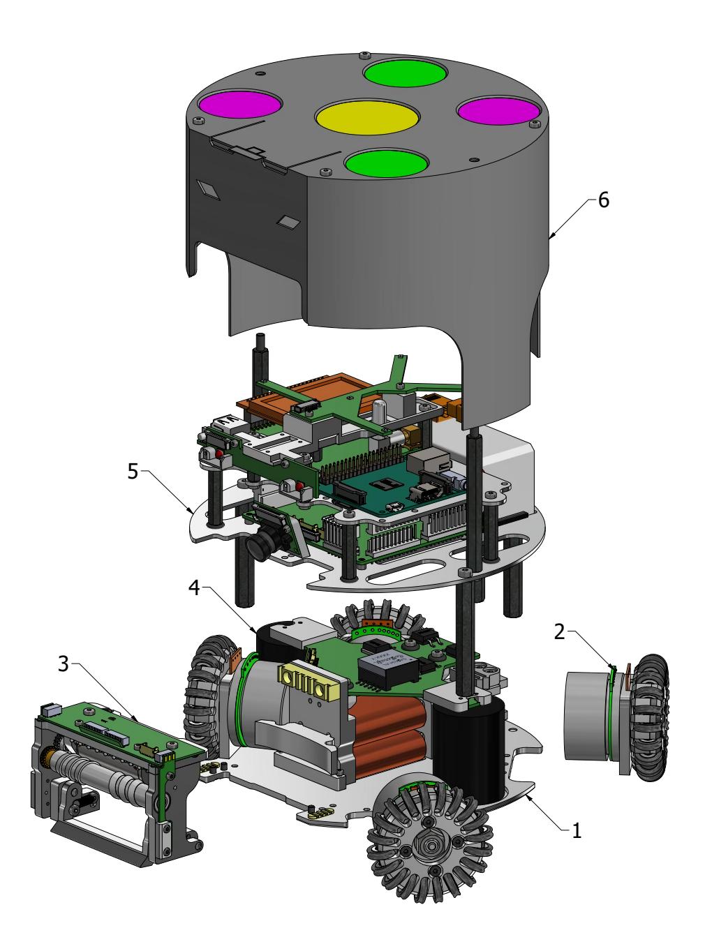
Modularity Concept Since v2016 our robots are very modular. This concept has been proven to be very benificial for development and during assembly as well as repair. Each robot has six major modules which can be replaced as a whole. Figure 2 shows an exploded view of these components.
Module #1 is the base plate. Most of the modules (except for the cover) are mounted directly on the base plate and fixed by screws at the bottom. An important detail here is to use screws with countersunk heads. They allow for an alignment of parts on the base plate. Moreover, they ensure that the bottom surface of the robot is as flat as possible, minimizing friction effects. Module #2 is a powertrain with wheel. In the current configuration four wheels are used with a front angle between the robot's X axis (parallel to the front) and wheel shaft of 31° and a rear angle of 45°.
Module #3 is a dribbler module. It includes the dribbling motor, the dribbling bar, a gear connection between them and electronics for the front break beam to detect the ball. Furthermore, it includes a shovel to translate a linear kick impulse to a rotational impulse for chip kicks. Module #4 is a kicker module. It consists of two rectangular plungers, one for flat kicks and one for chip kicks, two coils, and a capacitor charge PCB with two capacitors.
Module #5 contains the primary electronics stack. That includes a battery, a power board for motor drivers, a mainboard for control, a Raspberry Pi for computer vision algorithms, and a set of auxiliary boards. This module makes extensive use of standard distance bolts to stack the different layers. No custom parts are used here, thus reducing overall cost. Module #6 is a 3D printed cover with standard SSL Vision pattern.
The modules listed above are usually replaced as a whole during a competition to keep time for repairs as low as possible. This allows the team to repair robots not only after a game but already during a game. Experienced team members can replace a dribbler or powertrain unit in less than two minutes. This design allowed us to mostly have the maximum permitted number of robots on the field and have them fully functional.
Manufacturing Methods Some SSL robots have evolved to a highly-intergrated and compact platform for a special purpose. This is only possible with custom parts and their optimization. Commercial Off-The-Shelf (COTS) components usually do not fullfil the strict size requirements of the SSL.
Most components in our robots are manufactured by milling 7075 high-strength aluminum. It offers a low weight and high stiffness at a reasonable price. Some parts without pockets are manufactured via laser cutting. An alternative to laser cutting is using a waterjet, as it is done by other teams [7,8]. Two parts of our robots are produced by turning, which is the core of the dribbling bar and the subwheel bodies. The previous robot versions v2011, v2013, and v2016 contained custom parts only made by milling and turning.
With v2019 we introduced 3D printing and molding. 3D printing is a common and cheap manufacturing method nowadays. It is well suited for components which would otherwise be difficult to machine (e.g. small dimensions, complex structure, large volumes). However, 3D printed parts are not suited for components experiencing high stress (e.g. impacts). In the v2020 robot design only a few connecting elements and the cover are 3D printed. In contrast to that, other teams have already built most of their robot parts via 3D printing only [9].
Molding was used in the v2019 design for the first time in our robots. It was used to manufacture the dribbling bar with its helix shape. The v2020 design added some molded dampers for the dribbler.
2.1 Powertrain and Wheels
v2019 - 3D Printed Wheels The v2019 wheels were mostly 3D printed with standard PLA material and had a diameter of 33mm. 3D printing is cheap and the small wheels allowed them to be arranged in even 90° spacing between all wheels. This is the optimal configuration for an omni-directional robot as most of the non-linear friction effects linearize themselves.
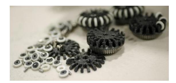
Although the wheels worked on our test field they suffered heavy damage on the RoboCup 2019 field in Sydney. The result of this can be seen in figure 3. Due to a deep carpet and solidly painted field lines covers of the wheels broke regularly and subwheels were dropped.
The top cover was fixed to the wheel base by three screws which directly went into holes in the PLA, without an extra thread. Due to constant repairs these holes were overused and no longer able to retain the cover. Occasionally, the cover was then lost and all subwheels were dropped at once. Furthermore, the white silicon O-rings were regularly broken and had to be replaced. As soon as a wheel started to degrade this was a self-amplifying process. A lost subwheel or O-ring led to direct contact of PLA to the carpet. Heat generated from friction led to melting PLA (PLA gets soft around 60°C) and rendered the wheel non-repairable.
v2020 - Solid Aluminum Wheels To obtain a more robust solution the 3D printed wheels are replaced by aluminum ones. However, milling wheels with the dimensions of the v2019 wheels is extremely difficult and expensive. Hence, the wheel size was increased. This implies that the ideal 90° spacing cannot be retained. Overall, wheel size was almost doubled compared to v2019 to a total diameter of 62mm.
The optimal wheel size for a SSL robot is always a compromise between multiple factors. Some key factors are: robot top speed, gear ratio, energy consumption, and available space. Most of the time a SSL robot is accelerating, it almost never moves with constant velocity. Hence, it makes sense to optimize the motor operating point for acceleration. This can best be achieved with a reduction gear. It decreases speed, but increases torque at the same energy consumption. This is done in the v2019 powertrain. This robot version can run for approximately two full games with one battery. For the exact endurance of v2020 robots no data is available yet.
To reduce the overall powertrain complexity v2020 robots now use a direct drive, i.e. no gears at all. The wheel is directly attached to the motor shaft. Main drawback of this change is the increased energy consumption. Given the v2019 endurance, this is an acceptable minus. Benefits are a more precise control as there is no backlash due to gears. Furthermore, it theoretically allows higher top speeds.
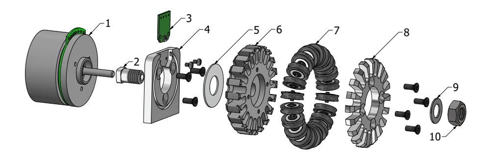
Figure 4 shows an exploded view of a complete v2020 powertrain. The shaft adapter (item #2) is glued to the motor (item #1) shaft with Loctite 648. It is very important not to machine the motor shaft. Steel dust or chips are attracted by the motor magnets. If they enter the motor its lifetime is significantly reduced.
A small PCB for an optical encoder IC (item #3) is inserted into the mounting block (item #4) which connects to the base plate. On the counterside, a reective optical encoder disk (item #5) is inserted into the back of the wheel base (item #6).
The integration of the optical encoder directly into the mounting block and wheel make this solution very compact compared to older versions. v2019 robots had magnetic encoders above the wheels, v2016 had optical encoders behind the motors. Both solutions took signicantly more space.
Subwheel Design Inserted into the wheel base are 20 subwheels (item #7). A wheel cover (item #8) secured with four screws tightens it to the wheel base. Items #5 to #8 form a wheel. The wheel can be removed from the shaft adapter by removing a hex nut (item #10), allowing for fast wheel changes. To ensure the hex nut does not loosen itself from vibrations a spring washer is inserted (item #9).
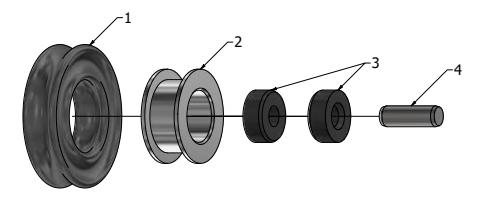
The v2020 subwheels are optimized based on experience with previous generations and publications of other teams [10]. Figure 5 shows an exploded view of the subwheels, they consist of four dierent parts. Item #2 is the subwheel body. Inserted into the body are two friction bearings (item #3) and a dowel pin (item #4) as shaft. Friction bearings are available o-the-shelf from igus2 . The bearings are pressed into the body and oer a bearing with very low clearance. The bearing material is shock absorbing and has excellent dry-run capabilities.
An X-Ring is put on the roller body as a connecting element to the carpet to increase friction. X-Rings are superior to O-Rings when it comes to traction, but they have a slightly higher wear. As X-Rings oer two contact points to ground instead of just one like an O-Ring the circular wheel is approximated by 40 contact points, which results in a smooth movement (low vibration, low noise).
These subwheels are similar to v2016 design. However, v2016 did not use a friction bearing, which resulted in higher vibrations and also more wear around the axis. Hence, the center hole was becomming bigger over time, increasing clearance and leading to imprecise control.
www.igus.de, type number MSM-0205-02
2.2 Kicker
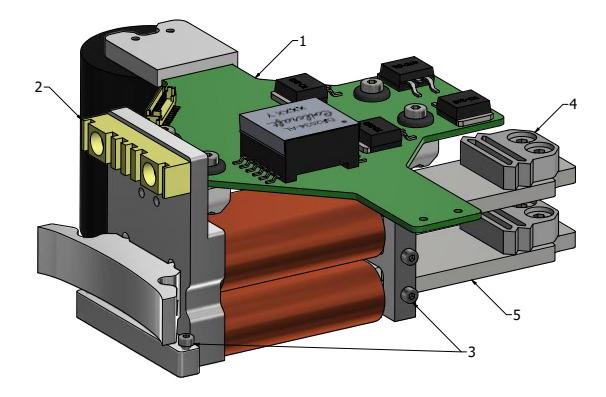
The kicker module integrates two coils, two plungers, and a capacitor charge PCB. An overview is shown in gure 6. Item #1 is the capacitor charge PCB. One capacitor is hidden for a better view. Details on the charge circuit can be found in section 3.2.
Item #2 is the rear damper of the dribbling device. It has to absorb the impact energy of received balls. It is made of a polyurethane rubber with a shore hardness of 30A3 , manufactured using a 3D printed mold. Item #3 indicates location for a pull spring. The spring itself is not shown in the image. The spring is required to pull back the plunger after a kick.
Item #4 is a damper for the plunger. It is 3D printed and made of TPU98. Despite being a relatively hard rubber, it is still exible enough and robust. Cutouts in the shape allow the dampers to be compressed upon impact on the rear mounting block. A method of damping the plungers is strictly required. Usually, the kick impulse is transferred to the ball and little energy remains to be absorbed. Nevertheless, if the ball is not present during a kick, the complete energy needs to be absorbed by the structure itself. Without a damper the energy would be transferred during a short time frame, resulting in a severe impact. By using a damper, the energy is transferred over a longer time frame. This mitigates structural damage to the rest of the robot.
Item #5 shows the rear part of a plunger, made of ferromagnetic steel4 . The steel alloy must be ferromagnetic. This part of the plunger is attracted by a coil made of enameled copper wire with a diameter of 0.63mm. Approximately 380-450 turns are used on 6-7 layers. A high-voltage, high-current pulse through the coil generates a magnetic field which attracts the plunger. The current flow direction does not matter, the plunger is attracted in all cases.
Half of the plunger is made of steel. The other half is made of aluminum which is not ferromagnetic. The steel part of the plunger is accelerated until it is centered in the coil. After it passes this point, the magnetic field will decelerate it. Hence, a plunger made of steel only would not work. Finding the optimal composition of coil parameters and plunger size as well as position is very difficult and either requires complex simulations or empirical data.
The v2020 kicker design uses a rectangular shaped plunger. It has only one degree of freedom left (moving forward and backward). v2019 used a round bar as plunger. It had one additional (undesired) degree of freedom since it could additionally rotate in place. To prevent this guiding blocks are usually required, which increases mechanical complexity. No deviation in kick strength was noticable when the shape is changed while the coil cross-section area and number of turns is kept equal.
Smooth-On VytaFlex 30.
Usually St37 or C45 low carbon steel
2.3 Dribbler
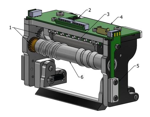
The dribbler module interacts with the ball and has infrared sensors to detect its presence and position. Figure 7 shows the main components of the dribbler. v2020 uses three gears (item #1) to transfer motor speed to the dribbling bar. All gears are of the same size. Hence, motor speed equals dribbling bar speed. The gear on the motor shaft and on the dribbling bar are made of brass and glued onto the respective components. The middle gear is made of polyketone and is just pushed on two small ball bearings. It is very important to have different materials on mating gears to reduce wear as one part can always yield in such combinations.
The dribbling bar is mounted into a ball bearing on each side. The helix shaped roller (item #6) is molded from polyurethane rubber with a hardness of shore $60A^5$ .
The dribbling motor in v2020 is a brushless motor with 55W and a rated speed of 17000rpm. The dribbling motor is used in short-term overload mode. That implies it is off most of the time but when it is used the rated power is exceeded, leading to heat build up. The winding temperature must not exceed $155^{\circ}C$ , otherwise the motor is permanently damaged. To monitor heat of the motor a temperature sensor (item #2) has been added to the IR controller PCB (item #4).
Apart from dribbling, the module also has sensing capabilities consisting of infrared diodes (receivers) and emitters. On the sides of the dribbler an emitter and receiver are paired to form a break beam. This is mandatory for a precise kick mechanism. Relying on vision data for this purpose is not precise enough due to the visions capture and transfer delay. The components of the break beam are protected by 3D printed PLA covers (item #5) to prevent damage in skirmish situations. Item #3 is an IR scan array, consisting of ve receivers and four emitters. An evaluation whether the array can be used to compute a more precise location of the ball in close vicinity is still ongoing.
As illustrated in 6 (item #2) the dribbler module is damped at the rear to absorb ball impact energy. To improve dribbling behaviour there is another shore 30A damper between the base plate and the dribbler module. This should reduce oscillations of the dribbler module while dribbling a ball [11].
v2019 robots used a smaller and higher speed motor (up to 60000rpm) with a double reduction gear to 20000rpm on the dribbling bar. Overall this gear was very loud, had a lot of vibrations, and high wear on the gear teeth. Due to size constrains ball bearings could not be used. All these problems are xed with v2020.
Smooth-On VytaFlex 60.
2.4 Cover
The v2019 as well as v2020 cover is made by 3D printing. Dierent materials and thicknesses have been evaluated. Empirically the best combination was PETG with a thickness of 1.2mm. The cover must not be too thick, otherwise it looses exibility which is required to eciently absorb contact energy and distribute it over a larger area. During the print of a cover (which takes up to 10 hours) layer adhesion is the most critical factor. Tests showed that the cover never broke within a layer but always at the connection of two layers. PETG oered the best layer adhesion as it is usually printed at slightly higher temperatures than PLA. Flexible materials like TPU98 were also tested but they are much too soft given the above thickness.
The key to a robust cover is a combination of the printed PETG cover with an adhesive lm over the complete area. PETG and adhesive lm form a compound material. Tests showed that the PETG cover can still break during heavy impacts but the design tolerates and expects this. Even if the PETG breaks the cover holds together by the adhesive lm without loosing functionality. As 3D printing is cheap it was accepted to print new covers when needed. After RoboCup 2019 only very few cracks were found on our covers, less than expected. Covers for v2020 need a cutout for the wheels. Hence, new covers are printed.
3 Electrical Design
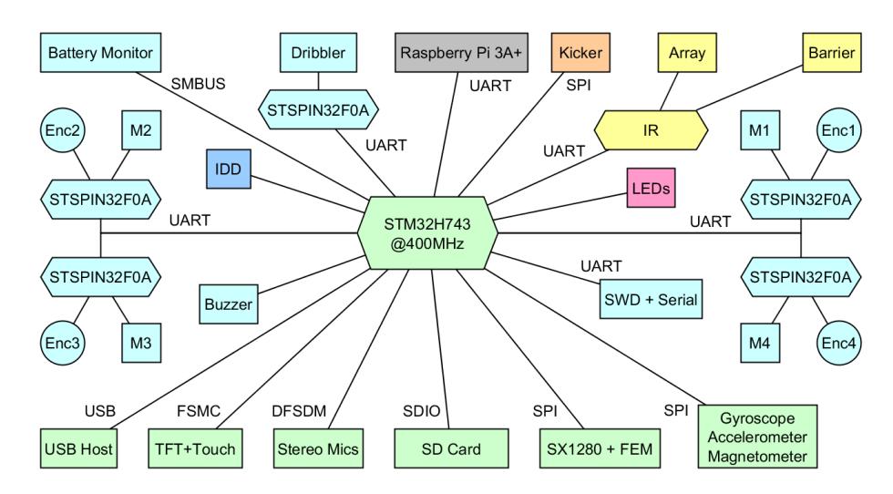
The electrical design of v2019 and v2020 robots is more complex than all previous generations. It consists of six dierent custom boards and one Raspberry Pi 3A+. Figure 8 shows an overview of all major components and their allocation to physical boards. The most important part are the mainboard (green) and the powerboard (light blue). They are connected via a ne-pitch ex cable.
In contrast to the mechanical part, the electronics remain mostly unchanged from v2019 to v2020. Only the IR controller and the pattern identication board have experienced minor updates (see 3.4 and 3.5). All components have proven to work reliably. Furthermore, due to multiple progammable microcontrollers this architecture oers potential for further improvements by software changes only. Without the need to respin a new electronics design.
Especially for new teams such a complex design can be overkill. Our v2016 robots demonstrate that a much simpler design can also work very reliably. Some v2016 robots are still in active use. They use only two custom boards. One mainboard including power electronics for motors and one board for capacitor charging and kicking (kicker board). This is also a more convenient solution.
v2019 and v2020 electronics have been extended especially for more autonomy and onboard processing. They are always running a state estimation, trajectory generation and position control loop onboard. The new design additionally allows more autonomous ball handling via a camera attached to the Raspberry Pi and the improved IR controller. If needed the Raspberry Pi can be exchanged for a nVidia Jetson TX2 compute module. As technical challenges of the SSL are trending towards more autonomy this design is ready for it.
3.1 Power Electronics
The powerboard contains all components which have to handle high currents. It incorporates ve brushless motor drivers based on the STSPIN32F0A microcontroller from ST Mircoelectronics, one for each motor [12]. Each motor driver communicates via a dedicated serial link (UART) with the primary microcontroller on the mainboard. This link also allows in-system reprogramming of the motor drivers from the primary microcontroller via ST's built-in bootloader. Previous designs used shared SPI connections for communication but this did not prove to be reliable. If one client on the bus fails it can potentially break the whole bus. Whereas individual UART connections work very reliably due to their independant RX/TX lines.
The STSPIN32F0A features a small microcontroller clocked at 48MHz with 4kB SRAM and 32kB ash memory. Each motor driver has a motor, its hall sensors, and encoder signals (if present) directly attached. At the moment, the motor drivers are only doing the commutation logic (6-step) to spin the motors and a common link current measurement. Velocity control is done on the primary microcontroller. Nevertheless, this architecture allows to implement more advanced control algorithms (e.g. sinousoidal control or eld-oriented control) in the future.
Apart from motor control the powerboard includes step-down converters to transform the battery voltage to 3.3V, 5V, and 12V. A battery current and voltage monitor and over-current protection are also included. The Lithium-Polymer battery has a nominal voltage of 22.2V, i.e. six cells in series and a capacity of 1300mAh.
The powerboard oers a single micro-USB connection for programming of the primary microcontroller. Via this connection, the 5V and 3.3V rails are powered as well. Hence, the robot can be programmed and most subsystems tested without a battery. If a battery is attached at the same time a load switch seamlessly switches to the battery to power all systems. This simplies development and testing of our robots, as no extra equipment is needed.
3.2 Kicker Circuit
The kicker circuit is responsible for charging a set of capacitors to a high voltage and discharging them through the kicker coils to kick the ball. The kick strength is directly proportional to the current owing through the coil. The current depends on resistance of the coil and supplied voltage. To achieve kick speeds up to the league limit of 6.5m/s a high voltage is required. The v2020 design uses a software-controlled soft-limit of 240V and a hardware-enforced hard-limit of 250V. A pair of capacitors with 250V rating and 1800µF are used, yielding a total of 3600µF and a stored energy of 112.5J. The capacitors are used together for a coil, not one capacitor per coil.
The charge circuit uses a yback converter topology based on the Analog Devices6 LT3751 capacitor charge IC [13]. This circuit can charge the capacitors form 0V to 250V in two seconds. Recharging after a strong kick takes half a second. An advantage of the yback topology is the isolation of high voltage areas from the rest of the electronics.
The kicker board does not have its own microcontroller. It is intentionally designed to be very simple to reduce the risk of fatal mistakes. It only has a SPI interface to an ADC, used to monitor capacitor voltage and two input lines to trigger a at or chip kick. These trigger lines are digitally isolated from the high-voltage area. The primary microcontroller monitors the capacitor voltage and stops charging at 240V. This is the normal operating mode. If this fails for any reason the LT3751 is congured for a hard-limit of 250V to ensure capacitors are never overcharged.
It is absolutely vital to design the kicker circuit as safe as possible and to do a proper failure analysis and mitigation plan. Failure to do so can result in serious injuries. As an additional safety measure our robots always discharge themselves upon shutdown. This way we can be relatively sure that a turned-o robot is also safe to touch and work on.
formerly Linear Technology
3.3 Mainboard
The mainboard is the primary sensor hub and communication link to the our AI software running next to the eld. All sensors and motor drivers are connected to the primary microcontroller. Consequently, a powerful STM32H7 with 400MHz has been chosen for data processing. Previous designs until v2016 used multiple powerful microcontrollers. That required a complex data exchange between them to ensure functionality. This led to an unstable communication.
Hence, we moved from multiple equally powerful microcontrollers to one very powerful primary one and multiple very small sub-microcontrollers with a simple interface. E.g. the communication protocol between motor drivers and primary microcontroller consists of only a single dened message for earch direction, exchanged at a xed rate of 1kHz. With this approach corrupted messages are of minor importance as the message will be transmitted again during the next cycle.
The mainboard has a full inertial measurement unit (IMU) consisting of a gyroscope, accelerometer, and magnetometer. Gyroscope and accelerometer data is actively used in onboard sensor fusion for state estimation. Furthermore, position input from SSL vision is directly used on the robots. It is transmitted over a wireless link with a SX1280 chip from Semtech7 . To improve link quality an additional front-end module (FEM) is used.
Apart from vital functions the mainboard also oers a user interface and mass storage interfaces. The user interface is a touch display with a resolution of 320x240 pixels. It is used to display system status information and to edit wireless settings or execute self-tests. A touch display has the great advantage of being recongurable compared to xed hardware switches. For example, a recent change extended the selection of the robot ID from a maximum of 12 robots to 16 robots without any hardware modication. Only a change on the graphical user interface was necessary.
Mass storage interfaces are a full-size SD card slot and a USB host interface. The SD card is used to log state estimation and control data at real-time with 1kHz. That helps to debug and visualize controller performance problems which is mainly done with MATLAB. The USB interface can be used to update the rmware on all microcontrollers.
3.4 IR Controller
The IR controller board is shown in gure 7. Its primary function is the detection of a ball close enough to kick via a horizontal break beam. It consists of one infrared emitter and one infrared receiving diode followed by a transimpedance amplier which converts the IR diode's current to a voltage [14]. This voltage is then measured by an ADC in the IR controller's microcontroller (a STM32F031). The main challenge of the break beam is it's sensitivity to environmental lighting conditions as the infrared diode receives infrared light from the environment and the infrared emitter. The key here is to work with a pulsed emitter. In the current design the emitter is on for 500µs and then o for another 500µs. During each phase the resulting voltage is measured and stored. Afterwards the dierence of both values is calculated to determine if the beam is interrupted. This eciently eliminates all eects of environmental lighting. So far we never encountered any issues or interference with this detection method.
The v2019 design also introduced a infrared scan array mounted above the dribbling bar, slightly looking down. In the v2020 design this is also present. Five receiver diodes and four emitters are interleaved as it can be seen in gure 7 (item #3). The aim of this scan array is to determine a more precise position of the ball in front of the robot with a high update rate (300Hz or more). This shall then be used for more ecient dribbling or ball stealing capabilities.
Lastly, a temperature sensor is connected to the IR controller's microcontroller to monitor the dribbling motor. Previously, the motor temperature has been estimated by its consumed energy but it is more convenient and robust to measure it directly.
3.5 Auxiliary Systems
Auxiliary systems include a set of smaller boards. First of all, a Raspberry Pi 3A+ is mounted to all robots with a Raspberry Pi Camera Module v1 and a $140^\circ$ lens (diagonal field of view). It communicates with the primary microcontroller via a UART and takes 5V power from the power board. Its purpose is to do image processing for ball detection. This information can then be used to improve pass reception accuracy.
Secondly, the front LED board contains two high-power RGBW (red, green, blue, white) LEDs. For a nice appearance they are mounted behind the eyes of our front cover. They also have a practical purpose. We use them for live debugging during a game. Depending on the role of the robot (attacker, defender, keeper, supporter) the colors change. This allows us to quickly identify issues during role assignment (especially toggling issues where assignments oscillate). It is also a useful indicator for the audience during ball placement as it had its own color. Consequently, it was immediately visible if the game is in a normal state or in a stop state.
Lastly, an experimental pattern identification system is installed on each robot. Its purpose is to detect which cover is placed on a robot such that it can automatically adjust its internal ID. At the moment, the best option seem to be RGB sensors which detect the blob color from below the cover. Further tests are required to verify this system.
4 SSL Vision Blackout Technical Challenge (2019)
The technical challenge required the robot to approach a static ball as well as intercepting a moving ball. To achieve this, the Raspberry Pi used the video feed of the camera to locate the ball within the images. These pixel coordinates and diameter of the ball were then sent to the primary microcontroller of the robot via a serial link. The robot interprets this data and moves according to the desired task.
The chosen method for detecting the ball on the image is a scanlines approach. The camera module nativly provides the video data represented in the YUV color space. To highlight the orange ball on the image, we subtract the V channel from the U channel and ignore the Y channel, as it only provides brightness information. In the result of the U-V subtraction, orange pixels have a high positive value and blue pixels a high negative value. This representation for orangeness is then used for further processing.
In order to minimize the number of pixels used for processing, a small number of horizontal lines are placed in the image. For each of these lines a simple edge detection is performed. Positive and negative edges (representing the start and end of a ball in horizontal direction) are saved together as candidates. After all horizontal scans are completed, vertical scans are performed. For each candidate, the center of the horizontal section is used to place a vertical scanline to perform a similar edge detection. Using the start and end positions in vertical and horizontal direction, a rectangle can be placed around the ball. After tting a circle in the rectangle, the centerposition and radius of the circle are sent over UART to the main computer of the robot.
Further details can be found in a seminar paper available on our website [15].
5 Publication
Our team publishes all their resources, including software, electronics/schematics and mechanical design les, after each RoboCup. They can be found on our website8 . The website also contains several publications with reference to the RoboCup, though some older ones are only available in German.
Open source / hardware:https://tigers-mannheim.de/publications
References
- N. Ommer, A. Ryll, and M. Geiger. TIGERs Mannheim - Extended Team Description for RoboCup 2019, 2019.
- RLS, A Renishaw associate company. RLC2HD Datasheet, September 2017. https://www.rls.si/en/fileuploader/download/download/?d=0&file=custom%2Fupload%2FRLCD03_03RLC2HD_datasheet.pdf
- iC-Haus GmbH. iC-PX Series, 2016. https://www.ichaus.de/PX_datasheet_en
- STmicroelectronics. STM32H743xI Datasheet, July 2018. https://www.st.com/resource/en/datasheet/stm32h743bi.pdf
- Semtech Corporation. SX1280 Datasheet, May 2017. http://www.semtech.com/images/datasheet/sx1280_81.pdf
- Skyworks Solutions, Inc. SKY66112 Datasheet, March 2017. http://www.skyworksinc.com/uploads/documents/SKY66112_11_203225L.pdf
- R. De Iacoc et al. 2016 Team Description Paper: UBC Thunderbots, 2016.
- M. MacDougallc et al. 2018 Team Description Paper: UBC Thunderbots, 2018.
- O. Koopai et al. Immortals 2018 Team Description Paper, 2018.
- S. Ohno et al. KIKS Extended Team Description for RoboCup 2019, 2019.
- Z. Huang et al. ZJUNlict Extended Team Description Paper for RoboCup 2019, 2019.
- STmicroelectronics. STSPIN32F0A Datasheet, September 2017. https://www.st.com/resource/en/datasheet/stspin32f0a.pdf
- Analog Devices. LT3751 Datasheet, July 2017. https://www.analog.com/media/en/technical-documentation/data-sheets/LT3751.pdf
- V. Tran and J. Hernandez. Transimpedance Amplier Design, September 2015. http://www.cel.com/pdf/appnotes/an3025.pdf
- F. Seel and S. Jut. On-Board Computer Vision for Autonomous Ball Interception. Technical report, Cooperative State University Baden-Wuerttemberg Mannheim, 2019.