URoboRus 2020 Team Description Paper
Petr Konovalov, Dmitry Korolev, Dmitry Kapustin, Galina Reneva, Anastasiia Voloshina, Alexander Kalitin, Alexander Fradkov
Saint Petersburg University, Saint Petersburg, Russian Federation
Abstract URoboRus1 is a team from the Saint Petersburg University (Russia) intended to participate in the RoboCup Soccer Small Size League in 2020 in Bordeaux, France. This TDP presents the technical overview of our robots, control software system and main algorithms. It will be the first participation in this competition, consequently, a full description of all components is provided.
Keywords: RoboCup · robotics · multi-agent system · hybrid centralized system
1 Introduction
The core of our team consists of students from department of Theoretical Cybernetics of SPbU. We work together with engineers who developed robots and participated in writing TDP. We started to create our solution in September 2018 on the basis of robots. By the end of January, 2019 the team has passed qualification for Robocup-2019 in Sydney. This TDP is based on our TDP-2019 [1]. In sections 1-4 brief information from our TDP-2019 is presented for convenience of reading. Sections 5-7 are devoted to description of new developments made for Robocup-2020. In Section 5 new features of robot design are introduced. Section 6 presents a new structure of communication channel. New control algorithms are described in Section 7.
Successful participation in the professional Robocup-SSL league and consequent improvement of hardware and software are not the only aims for us. Related goals also include popularization of Robocup in Russia and development of new solutions for educational robotics, which is affordable for schools and universities. Some ideas described in this TDP can be used to achieve those goals.
2 Robots description
In this section we provide a brief description of the robot specification and some details about its implementation. More information about mechanical and electrical design can be found in our TDP-2019 [1] and in our repository [2].
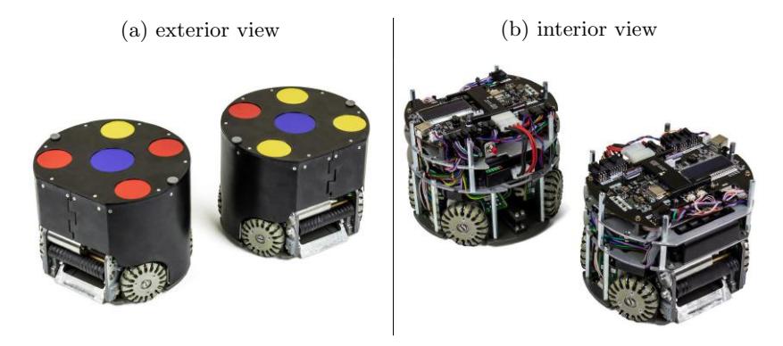
The robot consists of a straight kicker, a chip kicker, four omnidirectional wheels, and a ball spinning device (dribbler), which is equipped with a ball presence sensor.
The robot is equipped with four mid-flight brushless motors for omni-base and one more "dribbler" brushless motor to spin the ball. The motors and circuitry are fed by a removable battery with a capacity of 3000 mAh and an average voltage of 26 volts. The operation time is ≈30 minutes with an average current consumption of 6A. Details see in TDP-2019 [1].
3 Control software
This software was developed by using C++ with Qt framework [5]; this choice was partly motivated by its cross-platform nature. Software implementation of the algorithms was performed by using Matlab [6], partly due to its convenience at the stage of prototyping.
The software system basically consists of the following two parts:
- Centralized control tool [7] is commissioned to solve the following tasks:
- collecting data about field geometry and game situation from robots and SSL Vision [8]
- providing this data to the Matlab algorithm library, which calculates control signals for robots
- transmitting those signals to the robots
- Matlab algorithm library [9] provides to analyze the situation in the field and to assign the current roles to the robots based on this analysis. This library is also used by the Matlab Engine to calculate control signals to every robot with regard to its currently assigned role.
3.1 Centralized control tool
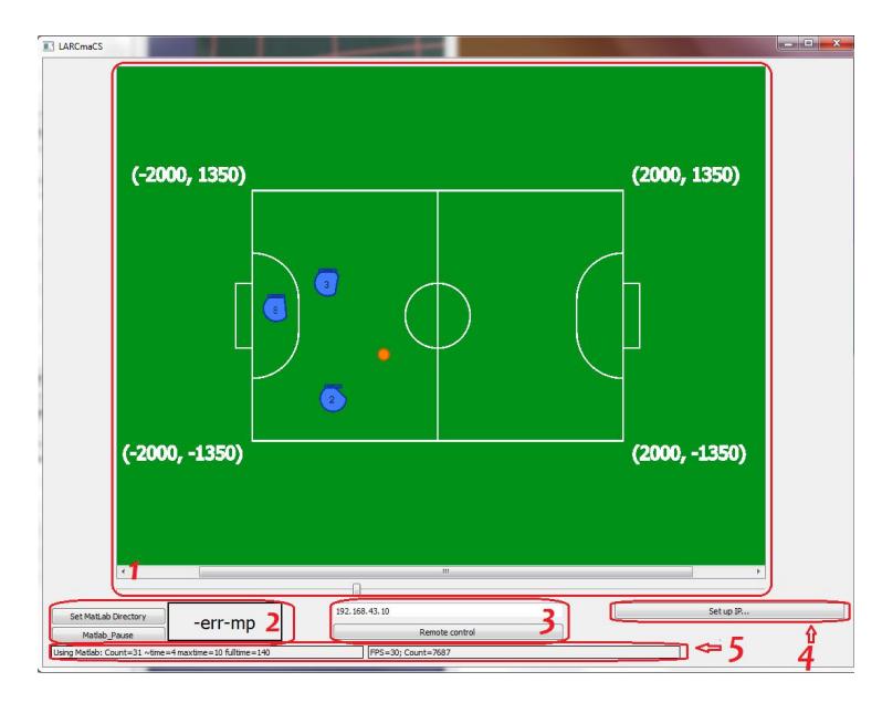
The connection with SSL server is established through SSL receiver module, which distributes the received data among all other modules. Centralized control tool sends commands to robots via Robots communication module. These commands are evaluated by Matlab engine and collected by Matlab communication module. UI module is responsible for graphical user interface which displays situation in the field and allows operator to start some algorithms in test mode or control robots manually. Therefore SSL server provides sensor information for control algorithms.
SSL receiver module The task of SSL receiver module is to support connection with SSL server and receive data from it. In this module we use standard classes that are supplied with SSL-Vision and are intended to receive and parse packets of Google Protobuf protocol [10]. The result of parsing is transmitted to Matlab communication module and UI module via Qt signals and classes. If packet from SSL server contains geometry we also generate Qt signal for updating field parameters which are saved as a Qt class and shared between Matlab algorithm library and UI.
Robots communication module Task of this module is to maintain connection of the centralized control tool with the robots, to receive data from their sensors, and to send control signals to the robots.
All commands to robot and data from him is counted in the robot system of coordinates. Each robot is continuously sending packets with data from its sensors via UDP datagrams.
Matlab communication module This module is responsible for launching Matlab engine, transmitting coordinates of objects on the field to Matlab Engine and extracting control signals for robots from engine after evaluation. We use Matlab C++ Engine API library [11] for getting access to Matlab engine from C++ source code. To underpin calculation of control signals we transmit the coordinates of the ball and robots, as well as sensors parameters to Matlab engine, and then evaluate file "main.ml". During evaluation special structure "Rule", which keeps control signals for robots, is initialized. After evaluation this structure is exported from Matlab engine and sent to Robot communication module.
- To work with Matlab engine we have introduced class MlData which keeps "Engine" and data of type "mxArray" for importing and exporting from Matlab engine (i.e., Yellows, Blues, Balls, etc.). To launch Matlab Engine we use function engOpen(). After that it is needed to specify output buffer for Matlab Engine by using engOutputBuffer(), set Rule to zero, and to specify the directory where files with our algorithms are accomodated.
- The coordinates of the balls and robots from the two teams are organized in arrays of doubles. When needed to be transferred the the Matlab Engine, these arrays are first copied to mxArrays. Then they are loaded to Matlab environment by using function engPutVariable(). Finally, Matlab engine evaluates "main.ml" with new loaded data.
- The control signals calculated in Matlab algorithm library are inserted into the structure Rule. For extracting it from Matlab algorithm library we use function engGetVariable().
3.2 Matlab algorithm library
As it was mentioned in section Matlab Communication module, general scheme of robots control consists of the next steps:
- receiving new SSL packet with data about robots (Yellows, Blues) and ball (Balls) positions on the field and loading them to the Matlab engine
- main.ml evaluating, during which a special structure "Rule" with control signals is being filled
- pulling this structure out and sending control signals to the robots
There are 5 variables which are shared between Centralized control tool and Matlab algorithm library – Blues, Yellows, Balls, Rule, ballInside. The first three variables describe data from SSL, the fourth one contains control signals for robots, the last one defines is ball inside any robot or not. All this variables are declared as double array (except ballInside, which is double scalar), both C++ and Matlab.
At the beginning of "main.ml" evaluation all needed variables and structures are initialized by using mainHeader function. During this function global structure RP are declared by using loaded data from SSL. This structure will be shared between all algorithms in the future evaluation. Structure RP contains the next main fields.
- Blue array of structures with information about blue robots (robot presence on the field, robot position, robot angle)
- Yellow array of structures with information about yellow robots (robot presence on the field, robot position, robot angle)
- Ball structure which contains information about ball position
- Pause flag which controls stopping and starting of evaluation
- Rule array of structures with control signals for robots
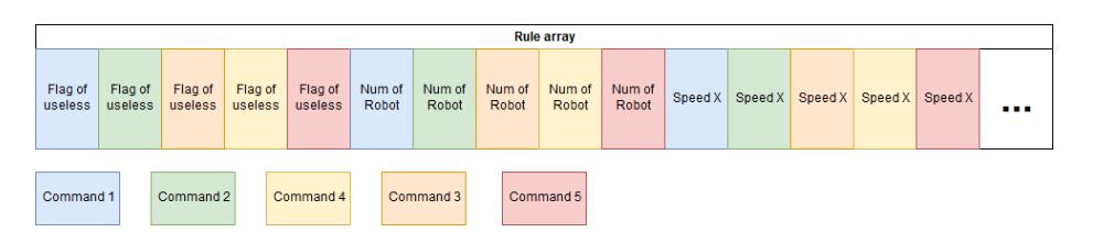
During evaluation "RP.Rule" should be filled with calculated control signals. Rule has the next fields:
- "Robot in use" flag controls do we need to send control signal to this robot or not
- Number of robot number of robot according to SSL Pattern [12]
- Speed X robot speed along X-axe of its local coordinate system
- Speed Y robot speed along Y-axe of its local coordinate system
- Kick forward flag controls should robot kick forward
- Speed R robot angular speed
- Kick up flag controls should robot kick up
Control signals are calculated using algorithms presented in section Matlab algorithm library. To stop evaluation we use a special function PAUSE, which switches "RP.Pause" flag. This flag is checked on each iteration at the beginning of main.ml and in case if it is true evaluation is stopped.
3.3 Build configurations
Compilers Initially, the project was developed for Windows platform only for the sole reason that then it would be easily accessible by school students. This motivated us to choose MSVC-compiler [13] for our application. Our current objective is to remaster the software for running on Linux. As a first step to this end, we have already converted the core programs to the to MinGW-compiler [14]. Our software system can be compiled by both of these compilers for Windows platform at this moment.
Architectures Our application needs Matlab. So as not to impose a restriction on the bit-version of the Matlab, both Matlab x64 and Matlab x86 were supported.
Continuous Integration Travis CI [15] with static code analyzer Vera++ [16], which automatically checks codestyle of pull requests, is used for automatic tests. It means that in the cloud we run Vera++ execution file which check downloaded from GitHub code (if it follows our fixed codestyle). We also added Appveyor CI [17] to our project. It means that our main application is downloaded and compiled by Appveyor server and if compilation succeed it is marked in GitHub as successful build. Although Matlab is needed for running our software system in full, but for testing build process of the project and running it, the testing build process calls for only Matlab Runtime Compiler [18], which is in free access. Our plans include transition from Matlab to MRC in order to make our software independent of any commercial products.
SSL At the moment we have to support our Centralized control tool with two versions of SSL-vision: old (2012 year) and new (2018 year). The old version is available on both Windows and Linux, while the new version is only available on Linux. We actively use the old one, because of more convenient way to deploy our setup. At the moment we actively try to port new SSL-vision to Windows.
4 Algorithms
The developed algorithms can be categorized into three groups: basic algorithms, advanced algorithms and roles (behaviour patterns). Now we illustrate every group by briefly describing its most important algorithms. Details can be found in our TDP-2019 [1].
4.1 Main terms
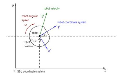
- SSL coordinate system global coordinate system associated with data received from SSL-vision
- Robot coordinate system local coordinate system associated with robot control model
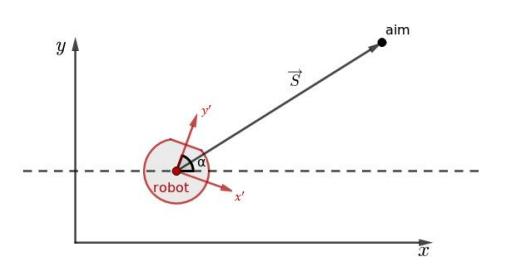
- Robot position consists of the Cartesian coordinates of robot center and the polar angle of robot in the SSL coordinate system – (x, y, α)
- Robot velocity is a vector of velocity in robot coordinate system $\overrightarrow{v}$
- Robot angular speed is angular robot speed ω
- Minimal robot speed is a minimal speed at which robot starts to move $v_{min}$
- Minimal angular robot speed is a minimal speed at which robot starts to rotate – $\omega_{min}$
- P, I, D are the proportional, integral, and differential coefficients of the considered PID-controller
4.2 Basic algorithms
The basic algorithms are as follows.
MoveToPoint This algorithm controls robot's moving to the destination point.
RotateToPoint This function controls robot rotation to the destination point.
GoAroundPoint This algorithm drives the robot around a given point at a given distance R and controls that robot is rotated to the point (looking after the point). If initially the robot is not at the requested distance from the point, the algorithm preliminary drives the robot to this distance.
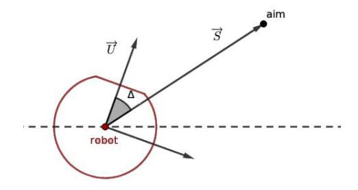
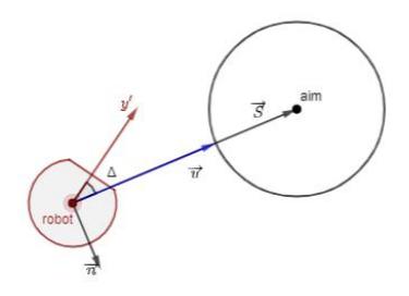
To calculate robot velocity we use MoveToPoint algorithm to point. Starting from this moment we combine MoveToPoint and RotateToPoint into function MoveToWithRotation, which moves and rotates robot to the destination point simultaneously
4.3 Advanced algorithms
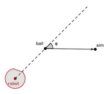
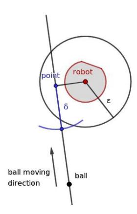
TakeAim This function drives robot to the line, which connects ball and aim. This function controls, that robot stops at the desired distance from the ball on this line.
If robot is in desired point, it rotates to the point using RotateToPoint. In other case, GoAroundPoint is called.
Catch ball This function allows robot to take a pass from other robot. The main idea is as follows. As soon as the robot is hit by the incoming ball, do not catch the rest the robot should move with velocity, which is co-directional with ball velocity and depends on it. In this case kinematic energy will decrease, and ball will not bounce off far.
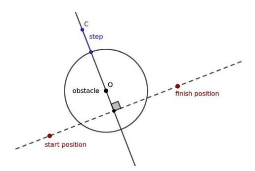
BuildPath This function builds path between starting point and destination point. There are several obstacles (defined as circles) on the plane between those points.
MoveToAvoidance This function controls movement of the robot to the destination point with obstacle avoidance. Obstacles are defined as circles.
4.4 Behaviour models
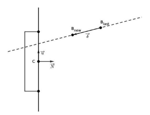
Goalkeeper This function describes goalkeeper behaviour. Goalkeeper is moving along the goal and its trajectory is a line. If estimated trajectory of the ball is crossing the goal, robot is moving to the point of their intersection. Estimated trajectory is a line calculated from previous ball positions.
$$t = \frac{\overrightarrow{CB}{new} \wedge \overrightarrow{u}}{\overrightarrow{\delta} \wedge \overrightarrow{u}}$$ $$point = B{new} + t \cdot \overrightarrow{\delta}$$
where ∧ – pseudo-scalar product.
Attacker. This function controls attacker behaviour. It provides kick in aim direction.
In this algorithm every combination of robot position, ball position and aim position belongs to one state of four possible states. Depending on what state describes the current arrangement of these objects robot makes a decision on further actions.
5 Improvements of Mechanical Design in 2020
(This section appears to be missing any direct introductory text before subsections.)
5.1 New Dribbler
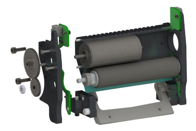
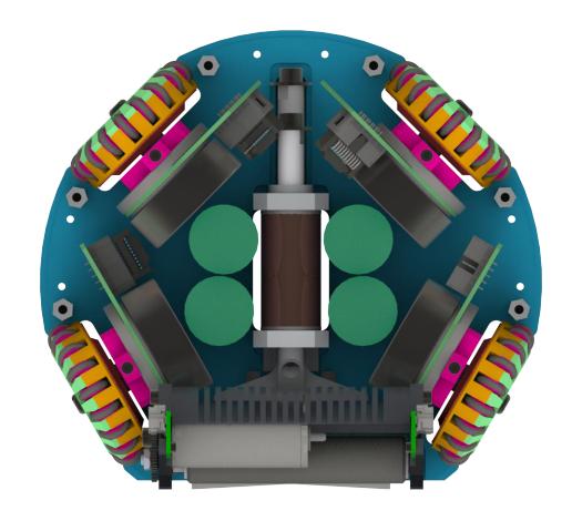
The most important part of improving the design of our robot was changing the dribbler module. In addition to the two main problems of the dribbler grabbing the ball and centering it, we worked on the manufacturability of the parts and simplifying the assembly and replacement of the dribbler roller when it is worn.
Capture the ball. In almost any scheme of the mechanics of the dribbler when centering the ball, it is pulled deeper into the robot with a change in the position of the roller. In our scheme, the axis of the roller moves along an arc of a circle. Previously, the length of this arc was too small for a full grip of the ball, in addition, the elastic element that returned the roller and the initial position was too rigid. We changed the design of the dribbler and now a spring is used as an elastic element, the rigidity of which can be changed with the adjusting screw. By adjusting the stiffness of the spring, we can change the pressure force with which the roller presses onto the ball. It may allow one to find the mode making retraction (capture) of the ball easier, and therefore improving control over the ball.
Centering the ball. We have changed the approach to centering the ball, and the bucket now plays the role of the guide, rather than the roller. Thus, we decided to simplify the manufacture of the roller, as well as its replacement after wear. Now the roller has a smooth cylindrical shape, and an indentation appeared in the bucket, along which the ball is attracted to the center of the robot while simultaneously contacting the bucket and roller. The smooth surface of the roller on the one hand simplifies its manufacture, and on the other hand slows down its wear due to the absence of drops and protruding parts. In addition to the two main tasks of capturing and centering the ball, we simplified the assembly and disassembly of the design of the dribbler and now to replace the role, you do not need to disassemble a significant part of the robot, but just remove one part. To protect the sensor of the presence of the ball from external influences, we made milled cavities in the suspension of the dribbler, in which the printed circuit boards of the sensor are installed.
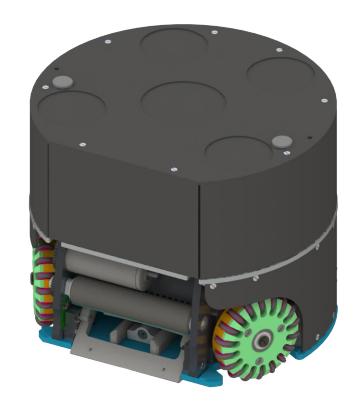
5.2 New Kicker
The overall layout of the robot has changed and we have more space in height to position the kicker coils. We changed their shape from rectangular to round, because of which they became higher, but narrower. Now, more side space from the kicker coils appeared, and we placed the capacitors vertically in the vacant space. This place was enough for the location of four capacitors instead of two, which allowed us to significantly increase the force of impact on the ball and now we can achieve a limit on the strength of the impact. In addition, the round shape of the kicker coils increases the manufacturability of parts, simplifying and cheap-ening their manufacture, and round coils are easier to wind. New design of robots is seen in Fig.
6 Improvements of the Communication System in 2020
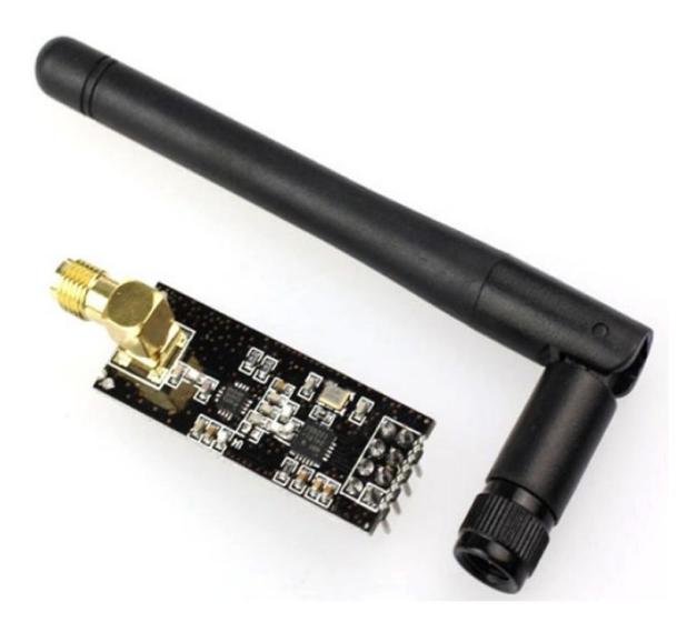
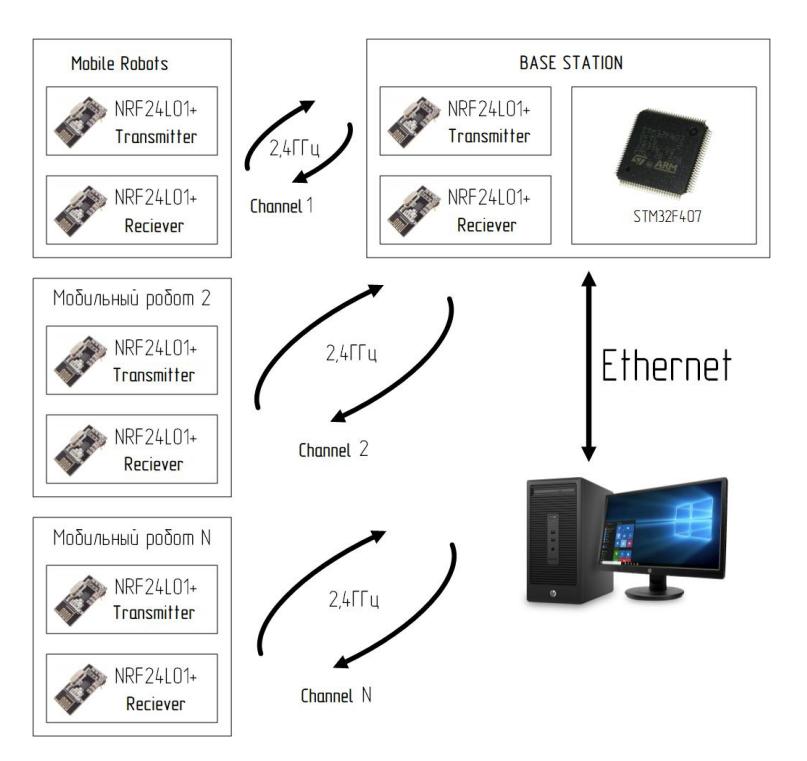
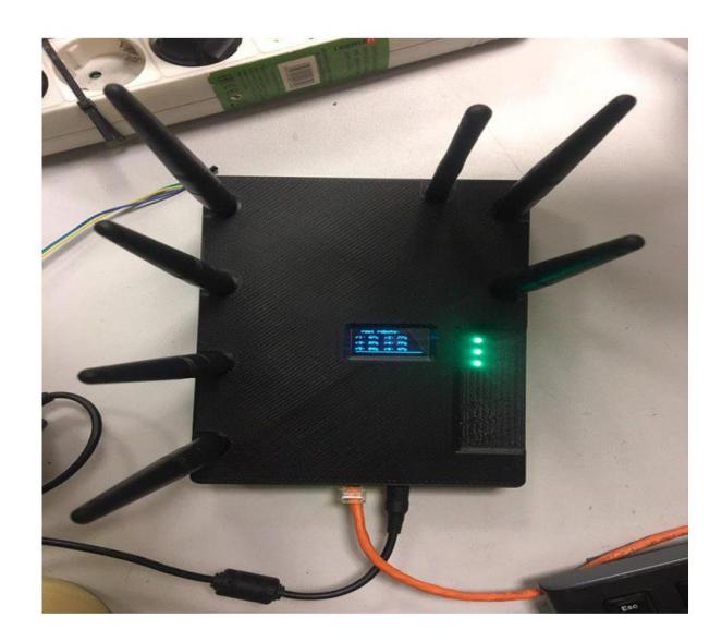
1 Previous design When we developed our team to the RoboCup 2019, the ESP8266EX module from Espressif Systems was used to provide communication between mobile robots and the base station, whose role is played by a personal computer. However during the competition the other Wi-Fi points will be online and a possibility of large congestion of devices using Wi-Fi that cause delays in the information transmission from mobile robots to the base station should be taken into account. To avoid interference and interruptions in communication with other devices, it was decided to arrange communication via radio channels and to use the NRF24L01+ radio module from Nordic Semiconductor. On the base station, there are 7 antennas, while each module located in robot has two antennas hidden inside robot. Based on this module, the following technical solution is implemented.
In the current version of the robots, the STM32F407VGT6 microcontroller communicates with the ESP8266EX module via the SPI interface. Then the ESP8266EX module transmits data via Wi-Fi over the network to which it is connected and, thus, the data goes to a personal computer, where it is processed and control commands are sent from the computer.
It is seen from the figure that to build a network, a separate transmission module and a separate reception module are used. This is necessary to ensure stable communication with the smallest delay time. Reducing the delay is achieved due to the lack of the need for constant switching of the module between the modes of "reception" and "transmission". Due to the fact that there are no suitable routers on the market for NRF24L01+, it is necessary to develop a base station. The base station communicates mobile robots with a personal computer. Since in the previous version of the system, a Wi-Fi-based network and the connection to the router via Ethernet were used, in order to avoid significant changes in the upper level control system, we tried to preserve the communication structure of the personal computer with the base station as much as possible. The base station is a printed circuit board on which there are two NRF24L01+ modules, a power supply, an STM32F407VGT6 microcontroller and an Ethernet physical layer converter chip.
7 Improvements of the Algorithms in 2020
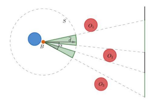
The improvements were aimed at better estimation of the state of the game and better taking the decisions. We formally posed and solved the task of finding optimal direction of the hit on goal in presence of many opponents. It is supposed that some models for motion of players and the ball are adopted. At the same time, the requirements for the model turn out to be quite natural and slightly restrictive, which makes the described algorithm applicable even with very accurate modeling of the movement of the ball and robots.
7.1 Notation
- ρ(·) is Euclidean metrics
- R is radius of each robot-player
- B is position of the ball
- {$A_k$}$^{M}_{k=1}$ is the set of the opponent robot positions
- $O^r = {(x, y)| ρ(A_r,(x, y)) ≤ R}$ is the set of points on the plane covered by a robot r
- $S = {(x, y)| x^2 + y^2 = 1}$ is the set of the directions
- $G(P, d) = {P + td| t ≥ 0}$ is the ray directed to d ∈ S from P
- a: b is the set of natural numbers between a and b
7.2 Optimal hit to the goal: problem statement
Let there be a possibility to measure ability of the robot to catch the ball sent to the direction d ∈ S from point B. Namely let a family of real functions fr(d) measuring ability of a robot to catch the ball be given. Here r is the number of the robot. We assume that the robot r will catch the ball if
$$f_r(\overline{d}) \ge 0 \tag{1}$$
Assume further that functions fr(d) have the following property:
$$\rho(O_r, G(B, \overline{d}_1)) > \rho(O_r, G(B, \overline{d}_2))^2 => f_r(\overline{d}_1) < f_r(\overline{d}_2)$$ $$(2)$$
In other words, the smaller the distance between robot and the trajectory of the ball, the easier the catching of the ball for the robot.
Consider the function f(d) = max r∈1 : M fr(d), characterizing security of the direction d. It is clear that the ball kicked along the ray d will be catched by some robot in the direction d under the following condition
$$f(\overline{d}) \ge 0. \tag{3}$$
Under above assumptions and notations the problem of search for an optimal direction can be formulated as finding d ∗ , satisfying relation
$$\overline{d}^* = \underset{\overline{d} \in S}{\operatorname{arg , min}} f(\overline{d}) \tag{4}$$
7.3 Optimal hit to the goal: algorithm
It is clear that it is sufficient to seek for the optimal solution of the problem over the set of the directions allowing to see the gates directly. Such a set will be denoted $S^g$ and called set of admissible directions. On the base station, there are 7 antennas, while each module located in robot has two antennas hidden inside robot.
Functions $f_r(\overline{d})$ in the set $S_g$ can be parametrized as follows
$$\varphi_r(\alpha) = f_r(\overline{d}(\alpha))$$
where $\alpha$ stands for the angle between the direction in question and extremal direction. Similarly,
$$\varphi(\alpha) = f(\overline{d}(\alpha)) = \max_{r \in 1: M} \varphi_r(\alpha). \tag{5}$$
and (4) is equivalent to finding $\alpha^*$ satisfying
$$\alpha^* = \underset{\bar{d}(\alpha) \in S_q}{\arg \min} \varphi(\alpha)$$
Note that the set $S_g$ is split to a few continuous segments and it follows from condition (2) that in every segment the function $\varphi$ defined in (5) is unimodal.
It is well known that the minimum of a unimodal function can be found with an arbitrary accuracy by methods of 1D search, e.g. Fibonacci or golden section method [19]. The search algorithm for $\alpha^*$ is as follows:
- Fix continuous subsets $S_g$ and corresponding uncertainty segments $[\alpha_1, \alpha_2], [\alpha_3, \alpha_4], \ldots, [\alpha_{2K-1}, \alpha_{2K}],$ where K is the number of continuous subsets.
- For any segment $[\alpha_{2j-1}, \alpha_{2j}]$ N steps of Fibonnacci search are performed. $\alpha_j^* = \underset{\alpha \in [\alpha_{2j-1}, \alpha_{2j}]}{\arg \min} \varphi(\alpha)$
- The estimate of the optimum is evaluated $\alpha^* = \underset{\alpha \in {\alpha_1^, \alpha_2^, \dots, \alpha_K^*}}{\arg \min} \varphi(\alpha)$
Function $\varphi$ is called unimodal if there exists $x^$ such that $\varphi(x)$ is decreasing for $x < x^*$ and $\varphi(x)$ is increasing for $x > x^$
7.4 Optimal hit to the goal: analysis and implementation
It can be shown that asymptotic convergence time of the algorithm is $O(M \ln \frac{L}{\varepsilon} \cdot \sum_{r=1}^{M} T(f_r))$ , where $T(f_r)$ is time of function $f_r$ evaluation, L is the gate width, $\varepsilon$ is the required accuracy of $\alpha^*$ evaluation. For $T(f_r) = O(1)$ , convergence time is of the order $O(M^2 \ln \frac{L}{\varepsilon})$ , which is appropriate for the game where $M \leq 8$ .
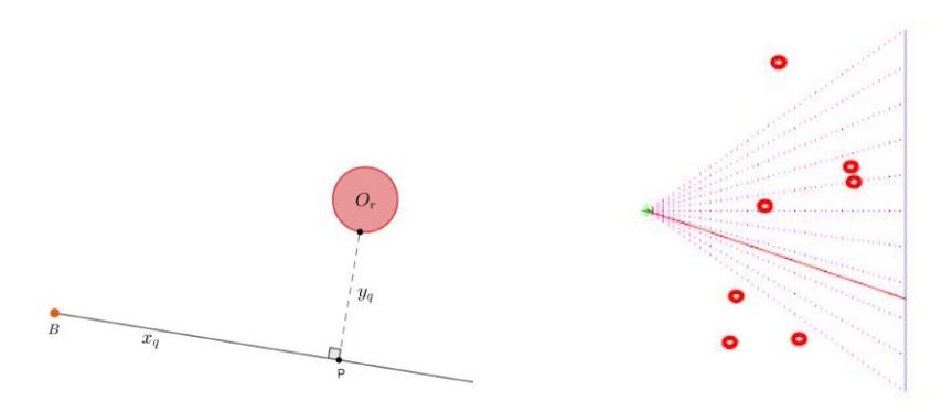
The above algorithm is implemented under assumption that velocities of the ball and robots is constant. Let u be velocity of the ball, v be velocity of the robots, $k = \frac{u}{v}$ . Let k > 1, i.e. robots are more slow than the ball. Choose conveniency functions $f_r$ as follows:
$$f_r(\overline{d}) = \max_{P \in G(B,\overline{d})} { \rho(B, P) - k \cdot \rho(O_r, P) },$$
Then $f_r$ means maximum distance between robot and ball when the robot reaches the ball trajectory taken with negative sign if ball has passed the crossing point earlier than the ball. In this case expression for $f_r$ is as follows
$$f_r(\overline{d}) = x_q - y_q \cdot \sqrt{k^2 - 1}$$
where $y_q = \rho(O_r, G(B, \overline{d}))$ , $x_q = \rho(B, P)$ , if P is the nearest point of the trajectory of the ball to the robot. Therefore condition (2) is valid and the algorithm is applicable.
During real game the above algorithm serves as the auxiliary one for attack. It works as follows:
- Evaluation of the optimal attack direction $\overline{d}^*$ ;
- The robot takes aim in the direction $\overline{d}^*$ . If it happens that $f(\overline{d}) < 0$ , where $\overline{d}$ is the direction of the robot sight then robot kicks the ball;
- After the robot takes aim $\overline{d}^*$ , it kicks the ball.
8 Acknowledgements
We wish to express our deep gratitude to Prof. Alexey Matveev (SPbU) for his review and useful advice for the scientific sections of this paper. Also, the project is supported by CyberTech Labs Co Ltd, a company behind the educational robotics kit TRIK [20], which is widespread in Russian schools, particularly to Anastasia Kornilova, the main organizer and author of the 2019 TDP URoboRus who put tremendous efforts to make our qualification at Robocup-2019 possible. We thank research institutions Russian State Scientific Center for Robotics and Technical Cybernetics (RTC) and Institute for Problems of Mechanical Engineering of Russian Academy of Science (IPME RAS). Special thanks should be given to previous research group (circa 2012-2016), which developed Robocup-SSL game for two-wheeled robots based on Lego, Arduino, and TRIK – Ilya Shirokolobov, Ruslan Sevostyanov, Kirill Ovchinnikov – for their responsiveness and advertency.
Finally, we wish to thank Presidental Lyceum of physics and mathematics 239 and CybetTech Labs Co Ltd for their valuable technical support on this project.
References
- 2019 TDP URoboRus, https://ssl.robocup.org/wp-content/uploads/2019/03/2019_TDP_URoboRus.pdf
- Electrical and mechanical components https://github.com/robocup-ssl-russia/schemes
- Russian inter-university robotics school, official webpage, https://vk.com/roboschool_vlg
- Robofinist, official webpage, https://robofinist.org
- Qt, official webpage, https://www.qt.io
- MATLAB, official webpage, https://www.mathworks.com/products/matlab.html
- Centralized control tool repository, https://github.com/robocup-ssl-russia/LARCmaCS
- SSL Vision system, official repository, https://github.com/RoboCup-SSL/ssl-vision
- Matlab algorithm library repository, https://github.com/robocup-ssl-russia/MLscripts
- Google Protocol Buffers, official webpage, https://developers.google.com/protocol-buffers
- Matlab C++ Engine API, official webpage, https://www.mathworks.com/help/matlab/matlab_external/engine-c-api-1.html
- Official SSL Vision standard pattern, http://wiki.robocup.org/images/9/96/Small_Size_League_-_Standard_Pattern_2011.pdf
- Microsoft Visual C++ compiler, official webpage, https://visualstudio.microsoft.com/ru/vs/features/cplusplus
- MinGW compiler, official webpage, http://www.mingw.org
- Travis CI, official webpage, https://travis-ci.com
- Static code analyzer Vera++, official webpage, https://bitbucket.org/verateam/vera/wiki/Home
- Appveyor, official webpage, https://www.appveyor.com
- Matlab runtime compiler, official web page, https://www.mathworks.com/products/compiler/matlab-runtime.html
- Press, W.H.; Teukolsky, S.A.; Vetterling, W.T.; Flannery, B.P. (2007), "Section 10.2. Golden Section Search in One Dimension", Numerical Recipes: The Art of Scientific Computing (3rd ed.), New York: Cambridge University Press.
- Cybernetic constructor set TRIK, official webpage, https://trikset.com official English webpage, http://blog.trikset.com/p/eng.html