Description of the 2020 Warthog Robotics SSL Project
Rafael G. Lang, Guilherme C. de Oliveira, Heloisa J. Barbosa, Adam H. M. Pinto, Pedro A. G. Pizarro, Arthur Demarchi, Ivan N. da Silva, Roseli A. F. Romero
Warthog Robotics University of S˜ao Paulo at S˜ao Carlos, 400 Trabalhador S˜ao-carlense Ave, S˜ao Carlos, S˜ao Paulo, Brazil
Abstract This paper presents the Warthog Robotics Magic project, developed since 2011 at the University of S˜ao Paulo at S˜ao Carlos, and the main improvements made to this RoboCup SSL project since the last competition. The project holds two Latin American championships and is under active development by the Warthog Robotics group. The mechanical structure is a mixed design using aluminum and composite materials and accommodates four brushed DC motors for locomotion. The system architecture is based on the GEARSystem library, with a decision tree strategy module, and powered by some filtering algorithms on the vision module. During the last development cycle, a telemetry system was developed in order to simplify the robot performance analysis. Additionally, a method for opponent path prediction is introduced and is expected to be ready within two years. The team presents full game capability with accurate and fast responses to strategy and referee commands.
1 Introduction
The Warthog Robotics is a research and development Robotics group from the University of S˜ao Paulo at S˜ao Carlos. The group counts with over 100 members from several knowledge areas, such as Computer Science and Electrical, Mechatronic and Computer Engineering, and develops Robotics technologies in several areas, applying most of them at Robotics competitions. Due to budget limitations, the team was not able to participate in the last edition of the RoboCup, but is still competing in local competition, including the following results in the Latin America RoboCup Open: the 2016 and 2018 first places, the 2017 second place and the 2019 third place.
The WR Magic is the RoboCup SSL robot of the Warthog Robotics group and its mechanical structure and electronic boards are the same from the last years, of which detailed information can be found in [1], [2] and [3]. The next sections briefly describe the robots and its supporting systems, as well as present the newest improvements of the WR Magic project.
2 Mechanical Structure
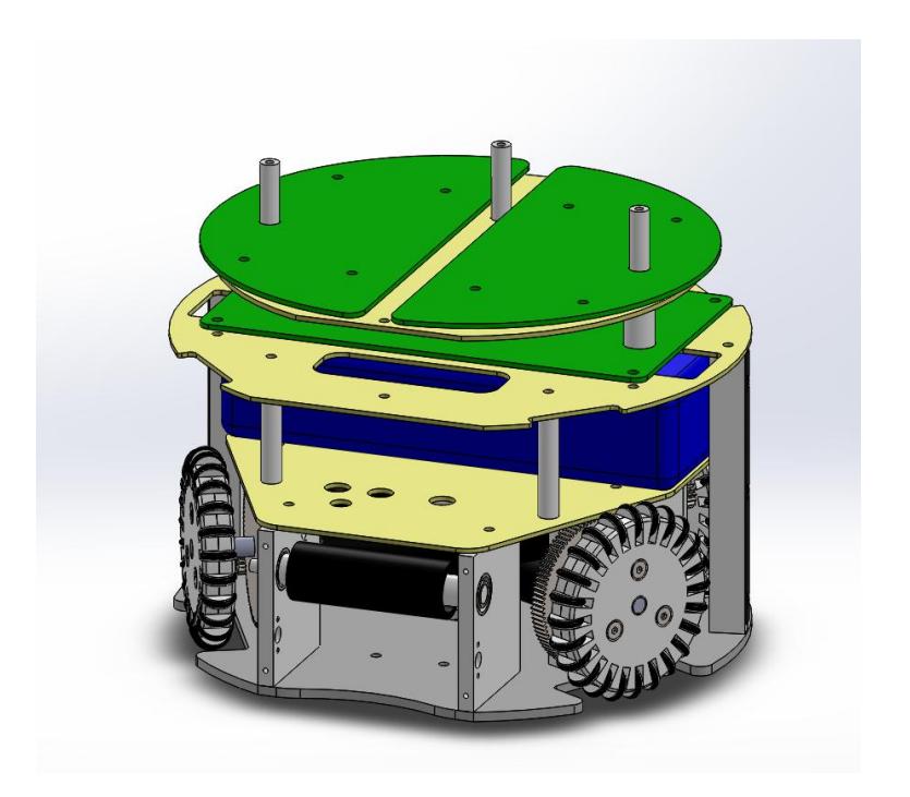
The internal mechanical structure of the robots is exactly the same one from the last years, composed of a locomotion system with four Faulhaber 2342 DC motors, a kicking device, and a dribble device mounted with shock absorber system. The upper part houses the three electronic boards, the battery and the kick capacitor using fiberglass plates. All mechanical structure is made of aluminum (gray parts) and composite materials (yellow parts) as shown in figure 1.
3 Electronic Devices
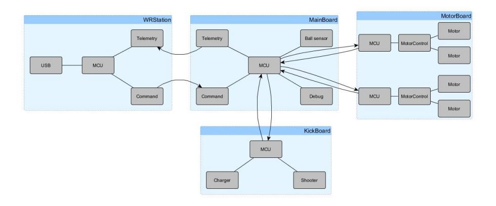
The electronic devices are the same of last years, composed of three electronic boards: MainBoard, MotorBoard and KickBoard. Detailed information about the boards can be found in [1], [2] and [3]. The architecture of the embedded electronics is shown in figure 2.
4 Computer Systems
The WR Magic project software is based on five sub-projects developed by the group: the GEARSystem library, the WRBackbone server application, the WRCoach strategy application, the WREye vision filtering application, and the WRStation radio communication application.
4.1 GEARSystem
The GEARSystem distributed library [11] is used to provide communication and distributed execution between system modules, as it focuses on remote procedure calls encapsulated as Robotics-related methods. This architecture allows the easy development of new software based on these main modules, and detailed information can be found in [1] and [2].
In the current implementation of the team, the Sensor module is the WR-Eye, responsible for receiving the data from ssl-vision and inserting it on the system. This module is composed by filters (Kalman, Noise, Loss and Multi Object) and more detailed explanation can be found in [2]. The Server module is WRBackbone, connection all modules on the GEARSystem architecture. The Actuator module in the WRStation, sending commands via USB to a custom station board that wirelessly tunnels them to the robots.
The commands sent to the robots are generated by WRCoach, the Controller module on GEARSystem architecture.
4.2 WRCoach
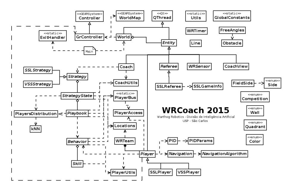
The coach is responsible for setting the strategy to the team: understanding the world model, defining behaviors, generating navigation paths and sending them to the system actuators. A simplified diagram of the software architecture is presented in figure 3. A full description of the software is available in [2], [4] and in Brazilian Portuguese at [13].
5 Improvements for 2020
[This section is developed in subsections below]
5.1 Telemetry system
The telemetry system that Warthog Robotics group has been working on has the objective to improve the capabilities and the WRMagic's gaming possibilities. One big problem that sometimes happened was running out or playing with low battery. During the games, the discharge rate of each robot differs by the amount of tasks that each one does in the match. Therefore, each and every game different robots needs to be recharged first, with the telemetry system, the real-time data will help to know that information and avoid running out of battery and other problems.
The telemetry protocol for the WRMagic, that has been developed, is compatible with another project from the IEEE Very Small Soccer League, the WR SubZero. Hence, understanding and developing the telemetry for one category, this research is refining both at the same time.
Through real-time data sharing, such as battery voltage, wheels velocities, motors currents, motors torque and kick capacitor voltage, the group is capable of analyzing, more empirically, the circumstances that the components operate. As a result, the battery lifetime and the causes for long term robot failure can be better inspected. Furthermore, a comparison of what was expected with what actually happens can be done, providing important data for advances in software, firmware and control systems.
As an example for the concept that was implemented, the following simplified version could be used:
$$[header \ m0 \ m1 \ \dot{x} \ \dot{\theta}]$$
Where:
header: header of the package
m0: real angular velocity of the motor zero [rad/s]
m1: real angular velocity of the motor one [rad/s]
$\dot{x}, \dot{\theta}$ : requested robot speeds
This simplified version of one package is transmitted 125 times per second in a different channel from the command radio in the robot, minimizing interference.
5.2 Opponent path prediction
As important as any artificial intelligence behavior may seem it is not effective if not applied in the right circumstances. That said, our group has focuses researches on identifying game state, which includes the opponents current behavior. With that purpose our first step in this direction is to recognize and predict the opponent's path.
To accomplish this goal it was applied a clustering algorithm to a large log database of players positioning during game, assuming that there are patterns of movement to be discovered in a soccer game. With those patterns in hand it is expected to, in the future, classify in real-time any player into one of said found patterns. Knowing in which pattern, or as referred to from now on, in which representative path each opponent is can lead to obtain vital information about game state.
The log database used, to obtain said representative paths, was obtained from the 2D simulation league, this decision was made based on the standard format in which said data is available at RoboCup archives. Later on it is expected that the same procedure could be adapted to run into a SSL log database.
The clustering procedure has Three major steps:
- Ball Possession Determination
- Filtering and Formatting
- Actual Clustering
Ball Possession Determination
The first step is the conversion from the standard format available on RoboCup archives [17] to a more readable comma separated value format. That is accomplished via the algorithm implemented by [19] with some minor modifications.
Along with the standardization the ball possession determination is done. This step is needed because, as discussed bellow, the filtering technique used filters complete "offensive plays" and to determine when those begin and end the ball possession information is used. To identify the ball possession the algorithm 5.2 was used.
Algorithm 1 Ball Possession
1: PS = 0.3 . PLAYER SIZE
2: PB = 0.085 . PLAYER BODY
3: KM = 0.7 . KICKABLE MARGIN
4: PMV = 1.2*1.05 . PLAYER MOVEMENT
5: KA = (PS + PB + KM)*1.05 . KICKABLE AREA
6: DD = 2*PMV . DASH DISTANCE
7: for player do:
8: if ball distance < PS+PB then . Evaluates If ball Possession Begins
9: begins possession
10: else
11: if ball distance < KA then
12: if ball relative speed > (2*KA)/1.5 then
13: if ball acceleration > 0.4 then
14: begins possession
15: else
16: not begin possession
17: else
18: begins possession
19: else
20: not begin possession
21: if ball distance < KA then . Evaluates if ball possession ends
22: not end possession
23: else
24: if ball distance < DD then
25: if ball speed > PMV then
26: ends possession
27: else
28: not end possession
29: else
30: ends possession
Filtering and Formatting
To validate the approach it was decided that the patterns should be found only in "offensive finalization play", with that in mind a player's play was defined as a array of a maximum of 150 coordinates, in sequence. The beginning of a play must be a dead ball or a change in teams ball possession and the end of a play must be a finalization trough the end line or a goalie catch.
if a finalization play is occurred all players data will be used in pattern recognition, not only the ones directly involved in the play. A script that applies this rules to the dataset was implemented.
After filtering the data must be formatted as the clustering algorithm inputs, for that another script was implemented.
Actual Clustering
The dataset obtained from the steps above will be used as input for the Trajectory Clustering algorithm TrasCLus [18]. This procedure takes the DBSCAN known features and definitions and approaches them with a new definition of distance that is used to measure distance between linear segments, transforming the classical point clustering algorithm into a linear segment clustering algorithm. The distance definition cited is a sum of three distances.
– Perpendicular Distance The perpendicular distance is defined by the second order Lehmer average between the size of the projections from one segments ends into another segment.
$$d_{\perp}(L_i, L_j) = \frac{l_{1\perp}^2 + l_{2\perp}^2}{l_{1\perp} + l_{2\perp}}$$
– Parallel Distance The parallel distance is defined by the smaller sized segment that connects one of the points of projection of one end of segment into another segment and a end point from the latter.
$$d_{\parallel}(L_i, L_j) = MIN(l_{1\parallel}, l_{2\parallel})$$
– Angular Distance The angular distance is defines as the euclidean size of a segment times the sine of the smaller angle between two segments.
$$d_{\theta}(L_i, L_j) = \begin{cases} ||L_j||.sin(\theta) & \text{se } 0^{\circ} < \theta < 90^{\circ} \ ||L_j|| & \text{se } 90^{\circ} < \theta < 180^{\circ} \end{cases}$$
Using the definitions of distance above, from [18], and the classic DBSCAN algorithm the trajectory clustering is made possible.
Preliminary Results
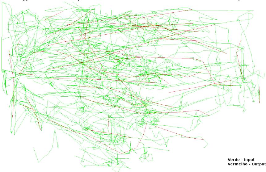
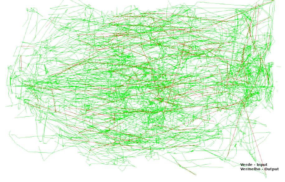
The clustering was applied to the 2D dataset as specified and some of the results can be found in figures 4 and 5. In red the representative paths, patters, found by the clustering and in green all the inputs for that test.

6 Conclusion and Future Work
Following the past few years budget directives of the group, the development made in 2020 focused in software and firmware. Minor improvements and bug fixes were made to the WR Coach software and a new medium term path prediction project was started.
A telemetry module was developed and incorporated to the robot firmware, providing means for enhanced performance analysis to be carried during the next competitions.
The current robot is robust, reliable and provides an excellent platform to the strategy systems. The implemented telemetry system will provide an important tool for further refinement and improvement in newer versions of the firmware.
Future works shall focus in software improvements, including the finalization of the opponent path prediction and a new study on embedded controllers efficiency.
7 Acknowledgments
The authors would like to thank all Warthog Robotics team for the hard work and friendship; the University of S˜ao Paulo for the facilities and financial support; the Embraer, OSG Sulamericana, Griffus and SolidWorks companies for the technical sponsorship; and all others that helped us during the project.
References
- Lang, R.G., Bernardo, A.M., Oliveira, G.C., Menezes, H.B.B., Ramos, L.C., Roque, L.G.S., Silva, I.N., Romero, R.A.F.: Description of the Warthog Robotics 2015 project. In: 2015 RoboCup (2015)
- Lang, R.G., Oliveira, G.C., Menezes, H.B.B., Rosa, N.S., Correa, R.A., Gomes, V.H., Silva, I.N., Romero, R.A.F.: Description of the Warthog Robotics 2016 project. In: 2016 RoboCup (2016)
- Lang, R.G., Oliveira, G.C., Barbosa, H.J., Rosa, N.S., Cepeda, B.H., Siqueira, A.H., Silva, I.N., Romero, R.A.F.: Description of the Warthog Robotics 2017 project. In: 2017 RoboCup (2017)
- Lang, R.G., Oliveira, G.C., Barbosa, H.J., Pinto, A.H.M., Rosa, N.S., Siqueira, A.H., Silva, I.N., Romero, R.A.F.: Description of the Warthog Robotics 2019 project. In: 2019 RoboCup (2019)
- Nordic Semiconductor: High Frequency 2.4 GHZ Wireless Transnciever. Data Sheet (2007)
- Olivera, V.A., Aguiar, M.L., Vargas, J.B.: Sistemas de Controle Aulas de Laborat´orio. EESC-USP, Brasil. (2005)
- Aguiar, M.L.: SEL359 Controle Digital,2015. EESC-USP, Brasil. (2015)
- Pressman, A.I.: Switching Power Supply Design. McGraw-Hill. (2003)
- Mohan, N., Undeland, T.M., Robbins, W.P.: Power Electronics Convertes Application and Design. Wiley (2002)
- Tse, C.K.: Complex Behavior of Switching Power Converter. CRC Press. (2003)
- Lang, R.G., Romero, R.A.F., Silva, I.N.: Development of a Distributed Control System Architecture. In: 2014 Latin American Robotics Symposium. (2014)
- Furlan, M. S., Silva, I.N.: Comparação de Controladores PID em Sistema de Malha Dupla em Robôs Omnidirecionais. In: 2018 Simpósio Internacional de Iniciação Científica da Universidade de S˜ao Paulo. (2018)
- WRCoach v2 documentation. Division of Artificial Intelligence - Warthog Robotics, available at https://www.assembla.com/spaces/warthog-dia/wiki/WRCoach_v2
- Wikipedia: PID Controller, available at https://en.wikipedia.org/wiki/PID_controller
- Control System Labs: Discrete-time PID Controller Implementation, available at http://controlsystemslab.com/discrete-time-pid-controller-implementation/
- Y. Lim, S. Choi, J. Kim, and D. Kim, "Evolutionary Univector Field-based Navigation with Collision Avoidance for Mobile Robot", The International Federation of Automatic Control, vol. 17, pp. 12787-12792, 2008.
- ARCHIVE Robocup. Palo Alto: RoboCup Federation, 2019. Disponível em: http://archive.robocup.info/Soccer/Simulation/2D/logs/RoboCup/. Acesso em: 14 out. 2018.
- LEE, J.-G.; HAN, J.; WHANG, K.-Y. Trajectory clustering: a partition-and-group framework. In: ACM. Proceedings of the 2007 ACM SIGMOD international conference on Management of data. [S.l.], 2007. p. 593–604.
- YARN, Z. 2D Log Mining. [s.n.], 2018. Disponível em: https://github.com/zenoyarn/2DLogMining. Acesso em: 14 out. 2018.