Triton RCSC 2021 Team Description Paper
Hongtao Zhang, Zihao Zhou, Pedro Orso, Duy Pham, Hector Montenegro, Francis Macapinlac, Haoen Luo, Jennifer Nguyen, Seph Shia, Anika Bhattacharya, James Li, Eric Wang, Danny Vo, Minxuan Liu, Xuanyan Hong, Joaquin Caso
University of California, San Diego, Institute of Electrical and Electronics Engineers
https://ieee-ucsd-robocupssl.github.io/TeamWebsite
Abstract The purpose of this paper is to describe the processes and methodologies used by our software, electrical, and mechanical teams in the design and production of a RoboCup SSL prototype robot meant to compete in the 2021 RoboCup Tournament.
1 Introduction
Tritons RCSC is an IEEE-sponsored club of mostly undergrad students from the University of California, San Diego. We are proud to provide opportunities to any student motivated to dive into the field of robotics and emphasize diversity and inclusion in our work. The club was founded in late 2019 with the goal of bringing UC San Diego onto the RoboCup scene while simultaneously opening doors for students to gain hands-on engineering experience through learning, promoting, and developing in the field of robotics. At its core, Tritons RCSC is a club that aims to be a fun, but educational experience.
We are the first club to actively work on RoboCup Soccer in UCSD, hence, the 2019-2020 season was to be split spent researching in the first half with production in the latter. However, once the Covid-19 threat took full effect, the club's efforts in hardware development were hindered by meeting restrictions, the closing down of our workspace, and physical separation of team members. Facing the rookie challenges of our first competition and Covid-19 related issues, we decided to delay our tournament application to the next season in hopes that restrictions would lift off, dedicating the rest of the 2019-2020 season to research and slight software development.
By the start of the 2020-2021 season we began focusing our efforts on production as it became clear that restrictions would not lift off anytime soon. The club made a big effort in efficient online collaboration, as well as setting up a small home workspace. We have done our best to work together while maintaining safe-distancing and following any Covid-19 related city or school restrictions.
Since we are still a young club, our aim is to compete in the B league in order to obtain experience for future tournaments. In this way, we can provide competition and a chance at besting other teams in the B league. Though our prototype is not perfect, we aim to make several improvements in the time before the competition. Once fully optimized, we will be able to produce a strong team of 6 robots for the 2020-2021 RoboCup tournament.

Team Tritons RCSC
| Details |
|---|
| Broadcom BCM2711 Cortex-A72 (ARM v8) 64-bit SoC @ 1.5GHz (Embedded in Raspberry Pi 4B) |
| STM32F427IIH6 Cortex-M4 (ARM) 32-bit C @ 180 |
| MHz (Embedded in DJI RoboMaster Development |
| Board Type A [abbrev. as RM]) |
| MPU6500 6DOF IMU (Embedded in RM), IST8310 |
| 3DOF Magnetometer (Embedded in RM) |
| 8 Megapixel Pi Camera |
| ST VL53L1X ToF (Not included in the current pro |
| totype, but will appear in a future upgrade to detect |
| ball-holding status) |
| WiFi between standard home router and our PC |
| DJI M2006 Motor with built-in encoders, Max 500 |
| rpm, Max 44W, 416rpm at 1 Nm, @24V |
| DJI C610 32-bit FOC ESC (interfaced with CAN |
| BUS), @24V, @Max 10A |
| GTF 50mm Omni Wheel |
| T-MOTOR MT2212-13 980KV Brushless Motor (cur |
| rent prototype), XING-E 2207 1800KV Brushless |
| Motor (future upgrade), ICQUANZX ESC BLHeli S |
| 6s 35A |
| LT3751 Capacitor Charger Controller IC, GA3459- |
| BL Flyback Transformer (turn ratio 1:10), IGBT |
| switch (FZT755TA PNP + FDS2582 NMOS), 2700 |
| Capacitor, @12v operating voltage, boost to 130V in |
| 272 ms |
| WEISE DS3218 Servo @5V 20KG |
| 22.2 V 6s LiPo, 1550 mAh, 100C |
Table 1: Robot Specification Table
| Details |
|---|
| Broadcom BCM2711 Cortex-A72 (ARM v8) 64-bit SoC @ 1.5GHz (Embedded in Raspberry Pi 4B) |
| STM32F427IIH6 Cortex-M4 (ARM) 32-bit C @ 180 MHz (Embedded in DJI RoboMaster Development Board Type A [abbrev. as RM]) |
| MPU6500 6DOF IMU (Embedded in RM), IST8310 3DOF Magnetometer (Embedded in RM) |
| 8 Megapixel Pi Camera |
| ST VL53L1X ToF (Not included in the current prototype, but will appear in a future upgrade to detect ball-holding status) |
| WiFi between standard home router and our PC |
| DJI M2006 Motor with built-in encoders, Max 500 rpm, Max 44W, 416rpm at 1 Nm, @24V |
| DJI C610 32-bit FOC ESC (interfaced with CAN BUS), @24V, @Max 10A |
| GTF 50mm Omni Wheel |
| T-MOTOR MT2212-13 980KV Brushless Motor (current prototype), XING-E 2207 1800KV Brushless Motor (future upgrade), ICQUANZX ESC BLHeli S 6s 35A |
| LT3751 Capacitor Charger Controller IC, GA3459-BL Flyback Transformer (turn ratio 1:10), IGBT switch (FZT755TA PNP + FDS2582 NMOS), 2700 Capacitor, @12v operating voltage, boost to 130V in 272 ms |
| WEISE DS3218 Servo @5V 20KG |
| 22.2 V 6s LiPo, 1550 mAh, 100C |

2 Mechanical Design
2.1 Drive Train
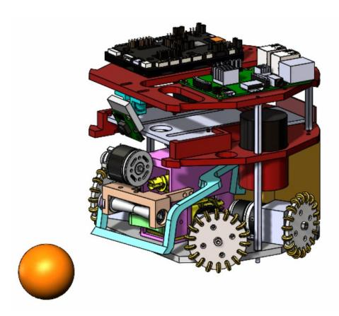
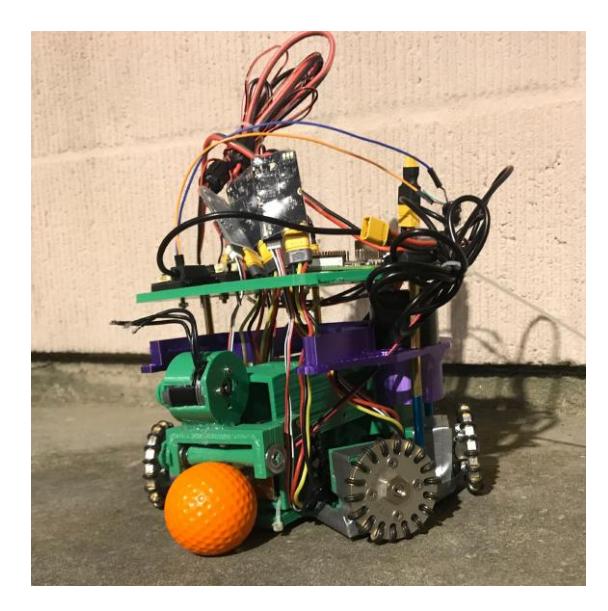
The robot uses four omni-directional wheels oriented at 26.66 degrees for both the front and rear wheels. This inclination in angles was made to provide more room for the rotating kicker-dribbler mechanism of the robot (Figure 1). The layers and mechanisms of our prototype (Figure 2) including the chassis were printed out of PLA. Our competition robot will be made of aluminum as it is sturdy without being heavy.
2.2 Kicker
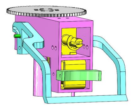
The kicker was designed to rotate to improve the robot's overall ball catching and kicking abilities (Figure 3) [17]. With the frontal wheels spread wider apart, there was more room for us to increase the length of the dribbler and implement the rotating kicker mechanism on the robot. We expect this rotating kicker to perform better than a stationary kicker in that it will be able to catch more balls by changing the angle. We are using a pre-built servo (WEISE DS3218 Control Angle) to rotate the entire kicker mechanism.

2.3 Dribbler
The position of the dribbler bar was calculated to offer maximum positional grip on the ball without covering more than 80 percent of the golf ball's cross sectional area. Geometric calculations were performed starting with the area of a circular segment to find the height and allowable width of overlap between the golf ball and the dribbler bar. We used conservative estimates for measurements to give tolerance for factors such as the golf ball sinking slightly into the carpet surface. Calculations for the width of overlap were derived from the formula for the area of a segment of a circle, and the height was modeled in Solidworks.
$$\begin{array}{c} R = 20.7 \text{ mm} \ \frac{A_s}{A} = 0.2 = \frac{\frac{1}{2}(\theta - \sin\theta)r^2}{\pi r^2} \Rightarrow \theta = 2.11314 \text{rad} \ w = R\cos\left(\frac{\theta}{2}\right) = (20.7 \text{ mm})\cos\left(\frac{2.11314 \text{rad}}{2}\right) = 10.1815 \text{ mm} \end{array}$$
2.4 Future Improvements Mechanical
When designing our dribbler we drew our inspiration from [12]. Although we considered different possible features, such as a mobile/rotating dribbler or passive retention techniques, we ultimately settled on the dribbler bar for its simplicity and flexibility of design. Although the current iteration of our robot only uses the dribbler bar for ball retention, future iterations could use it to put a backspin or topspin on the ball without major changes to the hardware.

Future Improvements Mechanical (continued)
When designing our rotational dribbler system, we wanted the dribbler to be able to 'catch' and retain the ball regardless of the angle of entry and contact position. Since our dribbler is now attached directly to the chassis of the robot, we decided on a self-centering mechanism to help align the ball. To do this, we added spiral embossed patterns to guide the ball to the center of the dribbler. We also considered shaping the dribbler bar to be concave, but this brought up concerns with the behavior of the ball at different entry angles.
Future Improvements Mechanical (continued 2)
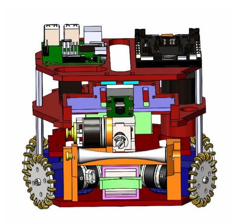
There were several issues with the printed prototype. We will change the material of our motor retainers in order to increase the robot's sturdiness and correct current imbalances in the drive train. The dribbler mechanism failed to work mostly because of a lack of friction in the material it was printed with. We have opted out of the rotational kicker idea for the current season, but will keep it in mind for future improvements. We will also focus on making the chipper more compact so that friction between the different parts is not an issue. Figure 4 is the new CAD design we are working on; the more compact chipper is in development and will be added in the future.
We also want to redesign our solenoids for next year. The pre-built solenoids we utilized to power the chipper and kicker were too slow and took up substantial space. It has been difficult to come up with a design that overcomes these difficulties. We are taking inspiration from KgpKubs 2020 TDP [3] on how they designed two rectangular solenoids that are compact and fit in the space of a single cylindrical solenoid. They note that they had a slow kicker due to a smaller number of winding on the solenoid due to dimensional constraints. We are taking that into consideration in our design; UBC Thunderbots [6] provide a method for winding in their 2020 TDP and if needed, we will utilize it. We are also considering RoboJackets [1] findings in their 2020 TDP on how the proportions of steel to aluminum in the pusher affect the consistency of the solenoid's performance (and how a curved kicker is inconsistent).

3 Electronics
3.1 Kicker Board
We found that the flyback topology would work best for our capacitor charging needs [12]. We designed the board with the LT3751 Capacitor Charger Controller IC and the GA3459-BL Flyback Transformer with a turn ratio of 1:10. The board is powered by a 12 Volt source from the DJI RoboMaster Board. The LT3751 IC was chosen due to its charging time efficiencies, but also due to the safety and simplification it provides for the circuit [12].
To release the charge into the kick or chip solenoids, we plan to use a AQZ105 Panasonic Solid-State Relay for each of the two loads to control if the capacitor will discharge through the kick or chip solenoids. This relay is a capable of passing large currents, which is needed because there would be an instantaneous high discharge of power through it and into the solenoid. To turn it on, we power an internal LED using ∼ 40µA, which sends a light signal into a photo sensor inside the relay. When detecting light, the photosensor then turns on the actual switch transistors and allows current to pass through it. This process consumes less power to turn on the solid-state relay when compared to a electromechanical relay. The main reason these transistors were chosen was because of their high voltage capabilities.
3.2 Future Improvements Electronics
A major issue is the lack of proper equipment to physically test the circuitry due to the limitations set by our university's policy during the COVID-19 pandemic. We understand the simulation is not enough and we should test the actual circuit itself, but due to our lack of equipment, including for our own safety when dealing with high voltages, we have been extremely limited in this. For the purposes of recording the application video, we used a pre-built standard capacitor charging power supply module tied to a manual switch in order to test the effectiveness of the CAD design. The use of this module also provided a good way to relate the applied voltage to the solenoid's force response and ball velocity from kicking.
4 Embedded Systems
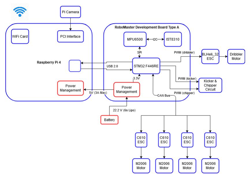
The purpose of the embedded systems sub-team is to fully integrate the hardware and software components of the robot. Different commands are sent to the robot's actuators to perform specific tasks including chipping, dribbling and kicking a ball. Each operation is predetermined by the algorithms' use of the sensor data. Our goal is to establish a robust network of communication between the physical movers of the system and the sensors coupled with software to exchange data efficiently. The team selected Universal Serial Bus (USB) as the communication protocol because of its reliability and speed. FreeRTOS served our multitasking needs with its priority assignments to threads [2]. FreeRTOS in our application provides heap management, message queues, and multitasking on a STM32 microcontroller, which is programmed with the STM32 Hardware Abstraction Library (HAL). A Raspberry Pi 4 serves as the team's main source of computational power and will process the robot's vision via a camera.
Embedded Systems (continued)
4.1 Actuator Control System
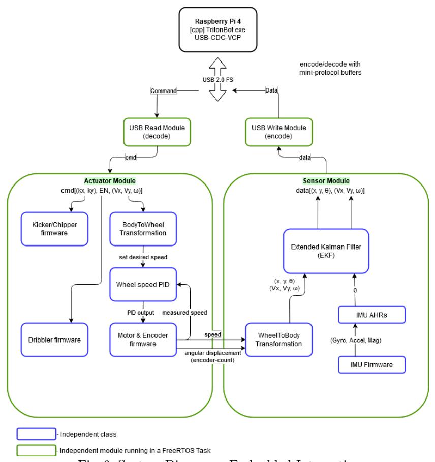
The actuators of the robot are the hardware components that are responsible for moving the machine. The goal of the team's control system is therefore to manipulate variables such as velocity, acceleration, and rotation to operate effectively. We applied the body-to-wheel transformation described in [5] to transform the desired translational and rotational velocity of the robot to the speeds of each spinning wheel. We adopted the Proportional–Integral–Derivative (PID) algorithm to control these wheel speeds.
The kicker and chipper of the robot use constants, kx and ky, to characterize the horizontal kick and the vertical chip, respectively. The constants represent the intensity of the kicks, relating voltage applied to kick velocity. In essence, the intensities are modified with a change of the PWM duty cycle sent to the Boost Converters. The dribbler works similarly, but instead of intensity parameters, it simply receives an enable signal to turn it on or off.

4.2 Synthesis of Data Using Sensors
The Inertial Measurement Unit (IMU) is a key part of our sensor module. The 9 degree-of-freedom (DOF) IMU system embedded inside the RoboMaster board integrates a gyroscope, accelerometer, and magnetometer. We planed to use the AHRS (Attitude and Heading Reference System) Algorithm to fuse data collected from the three sensors to give the measurement of the current heading angle and acceleration state of our robot [9]. Though the vision data from ssl-vision can also be used to infer the heading and acceleration, having an embedded IMU system supplies data with little latency and more accuracy.
The wheel-to-body transformation described in [5] transforms the angular displacement or velocity of each wheel measured by the corresponding motor encoders to the translational and rotational displacement or velocity of the entire robot. In addition, we plan to implement an EKF (Extended Kalman Filter) algorithm to fuse the motion information inferred from the encoders with the information inferred from the IMU system to give a more robust real-time motion estimation.
4.3 USB Integration of Actuators and Sensors
We utilized USB communication between the Raspberry Pi 4 and the RoboMaster board because of its high reliability on its differential signaling and fast speed that addresses the performance bottleneck of our distributed computing model involving multiple computing devices. The team was particularly interested in the virtual COM port (VCP) application of the USB because of simplicity.
4.4 Future Goals
We would like to create a set of system specifications for the robot that translate to requirements for PID control. Percent overshoot, settling time, rising time, and maximum response to a unit disturbance all serve as effective design parameters that will improve performance if considered carefully. The PID control system needs better algorithms to deliver angular and translational velocities.
To more efficiently drive the EC45 motors, we are considering designing our own circuit using DC-to-DC power converters. A properly designed motor drive will allow for instantaneous changes in voltage, forward motoring, regenerative breaking and better power flow.
The team seeks to improve the current wireless network provisioning because of the delay that comes with Wi-Fi. We plan on researching the benefits of radio communication over Wi-Fi to ultimately increase the speed of information transfer.
AHRS integration has not been properly configured yet, hence the team is steadfastly working on it. The EKF is also a necessity because of its strategic estimation of position and velocity with robustness.

5 Software

5.1 Architecture
Inspired by the inter-process Publisher-Subscriber system in ROS (Robot Operating System), we implemented our own simplified Publisher-Subscriber system for convenient inter-thread communications [15]. There are two sub-classes of our Publisher-Subscriber system. The first subclass has the intermediate message channel implemented with synchronized fields of generic type, which provides non-blocking methods for publishing and subscribing. The message channels of the second subclass is implemented with message queues, which provides synchronized publishing and subscribing, as well as the additional feature of data traffic control. The functional building blocks of our programs are called modules. Each of the modules runs in its own thread, with an arbitrary number of publishers and subscribers establishing communications with another module.
For Java development, EJML (Efficient Java Matrix Library) was used for linear algebra computations; Protocol Buffers were used for data serialization; and Standard Java Net Package and Java Concurrent Package were used for network socket communications and multi-threaded programming. With C++ development, the Armadillo library was used for scientific computation [13]; Protocol Buffers were used for data serialization; the Boost Library was used for socket programming, asynchronous communication, multi-threading, logging, and time-sensitive programming [14]; and RapidJSON was used for parsing settings and configurations [16].
Architecture - TritonSoccerAI Software
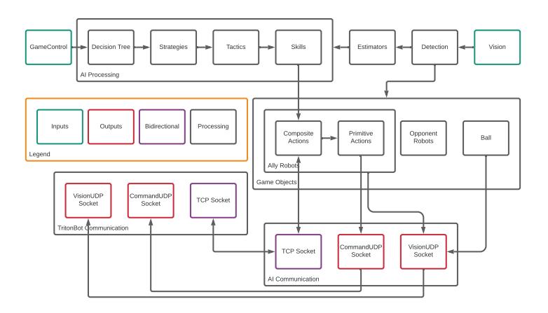
TritonSoccerAI Software (Java) TritonSoccerAI (see Figure 8) is the AI application that runs on the central field computer. An abstraction was made where each logical task is encapsulated as a module. Some notable modules in TritonSoccerAI are the vision module, the detection module, the AI module, and the ally robot's game objects. The vision module receives information about each robot and the ball as a protobuf packet. This information is published to the detection module, which processes the packet, calculating the velocities of various objects and translating the reference coordinate system into a team-specific perspective. The detection module publishes this information to each of the ally robot modules facilitating the execution of robot skills. The AI module receives information from the vision module and the detection module. This information is used to determine an overall strategy, the specific tactic, and then the AI skill. Each ally robot contains a pathfinding class that generates obstacle-avoiding paths. Allies are directed to perform skills by the AI class. Each ally module performs the specified skill by further decomposing the skill into primitive movements, which are then sent as UDP protobuf commands to TritonBot. The TCP socket is used for establishing the connections with the robots, and occasionally receiving state information from the robots, such as the state in which the robot is dribbling the ball.
Architecture - TritonBot Embedded Application Software
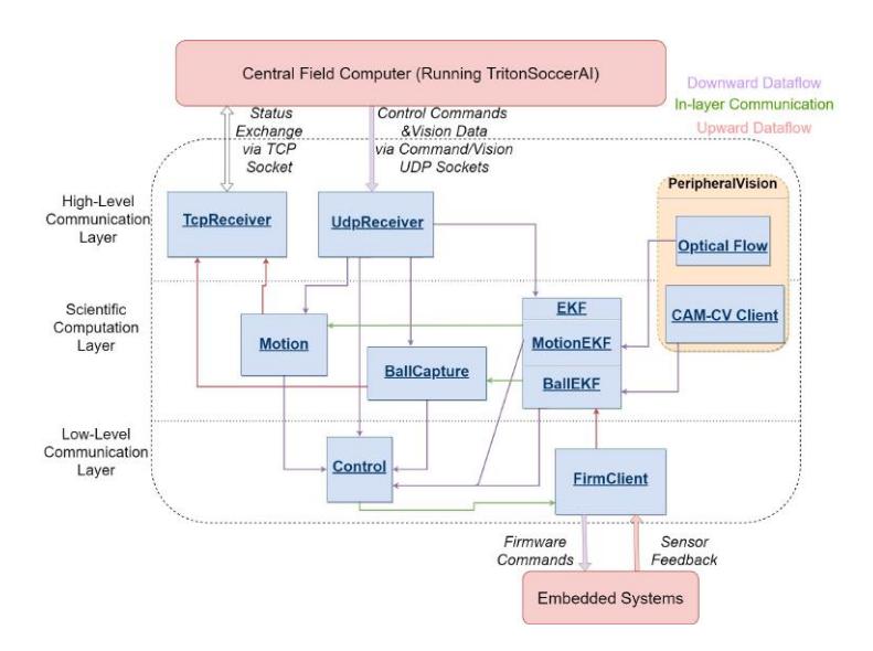
TritonBot Embedded Application Software (C++) TritonBot is a c++ program that runs on the Raspberry Pi 4 SBC (Single Board Computer) of every robot. It can be seen as an intermediary between TritonSoccerAI and the low-level embedded systems, as illustrated in Figure 9. The program relays commands and data sent from TritonSoccerAI and performs the necessary format conversions, affine transformations, control algorithms, automatic procedures, and the main EKF estimation. In addition, we plan to include an on-robot camera to be processed in the Raspberry Pi as a simultaneous ball detector and visual odometry. The major purpose of this program is to support more computationally heavy algorithms running on the robots while offloading the computation overhead inside STM32.
5.2 Algorithms
Path Finding Algorithm In this subsection, we explain the design of a trajectory-based dynamic path finding algorithm. Our path finding framework is mainly based on Jump Point Search (JPS) [7], which has been commonly used in video game development since 2011. The algorithm is proven to be fast and reliable, finding near-optimal trajectories of robot in a reasonable amount of time.
Prerequisite for the Path-finder Design Ideally, the pathfinding algorithm should be executed independently for each robot 100 times per second. It restricts the computation time for each pathfinding to be within 10 ms. In the Robocup SSL scenario most parts of the bounded space are free from obstacles. An efficient pathfinding algorithm should make use of this prior knowledge.
Any-angle path planning We discretized the 2-D continuous field into grids with blocked and unblocked nodes. The optimal form of the found path should be a set of vertices such that we could use the first edge to tell a robot which direction and how far it should approximately go. We start by implementing a Theta* algorithm [11], which is an any-angle version of the A* Algorithm. In short, it interleaves smoothing steps that check whether a vertex has line-of-sight to its descendants with A* searching steps. The resulting paths are reliable, but the algorithm is slow for distant points, as the number of visited points skyrockets.
Jump Point Search Jump point search (JPS) is an optimal algorithm for finding a path when there are few obstacles [7]. It skips most neighbors when searching straight or diagonally in free space. Checking extra neighbors is only invoked (which is called "forced") when obstacles are encountered. Such an advantage makes it suitable for the task. Although it finds discrete grid paths, the paths can be post-smoothed by checking line-of-sight in a fashion similar to Theta*. We call this modified version JPS-PS (post-smoothing).
Endpoint-In-Obstacle Handling We set the dynamic obstacles(other robots)' radius to be much larger than the actual robot radius to maintain a safe distance to other robots. It means when a robot accidentally gets too close to another robot, the beginning of the path may be in the obstacle. We handle this by performing a BFS from the start node to the first unblocked node, such that the robot is guaranteed to leave the obstacle robot in the safest direction.
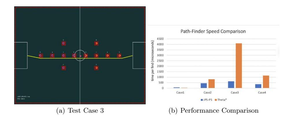
Experiments We compare JPS-PS and Theta*'s performance using four different test cases: finding a path across
- the center circle without obstacles
- half of the field with four obstacle robots
- the full field with eight obstacle robots
- the full field without obstacles
Figure 10(a) visualizes the discretized field, blocked nodes (in red), and JPS-PS path (in yellow) for test case 3. The result is shown in Figure 10(b). When the path is short, JPS-PS needs to perform some extra checking and is slightly more time-consuming than Theta*. As the path distances and number of obstacles increase, the time needed by Theta* increases a lot while JPS-PS still costs a reasonable amount of time.
Algorithms - Passing Planning Algorithm
Passing Planning Algorithm Our passing planning algorithm is mainly inspired by the pass-ahead algorithm used by the CMDragons team at the RoboCup'13 competition. [4] The key components of our algorithm are an accurate estimator of time taken for a robot or ball to arrive at a certain location given its initial state, and three probability maps for continuously finding good passing and assisting locations.
Robot and Ball Time Estimator Compared with the precursor [8], our time estimator features more data-driven, non-parametric methods, such that it is applicable to all kinds of robot structures, ball textures, ball sizes and does not require many tuning efforts.
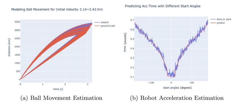
The ball model is essentially learning a functional relationship between the initial (kicking) velocity, the time, and the distance ball traveled. We collect ball model data by shooting the ball from the origin with initial velocity in the range of [1.00, 4.00] m/s with an interval of 0.01, and recording the ball's distance at constant intervals until the ball's speed is below a threshold.
The recorded data reveals a strong noise in the initial velocity. To eliminate the noise, we reassign the speed of each record based on the rank of its distance. Figure 11(a) demonstrates that the pre-processed ball movement data can be accurately captured by a fifth-degree polynomial. We drop all the terms containing no time to enforce that when the time is 0, the distance is also 0. The maximum distance the ball can travel with an initial velocity can be estimated by minimizing the velocity function using gradient descent.
We simplify the robot movement to be in four stages: rotation, acceleration, maximum speed stage, and deceleration. The maximum speed the robot can travel in each direction can be accurately calculated using the robot's speed at 0 and 90 degrees using a torque model. We assume constant acceleration and deceleration, both proportional to some power of the maximum directional speed. Figure 11(b) shows that such a model effectively estimates the acceleration time at any angle with very few parameters. The rotation time taken for each angle is modeled by a cubic function, and the total movement time is estimated as the sum of time for all four stages.
The learned robot and ball time estimators are simple, fast and robust, accelerating the probability map computation.
Algorithms - Passing State Machine
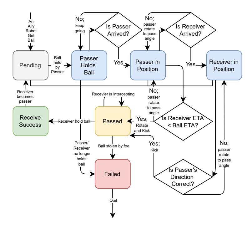
Passing State Machine We used a state machine similar to the Simple Temporal Network described in [4] to perform a passing routine, see Figure 12. The routine is initiated when the ball is under an ally robot's control, and the passer and receiver are locked (can't perform other behaviors) until the routine is finished. It is noteworthy that most of the time, the passer kicks the ball before the receiver arrives at the receiving location, achieving a pass-ahead coordination.
Algorithms - Passing Probability Map
Passing Probability Map We used a probability map similar to the one mentioned in [4] to decide which robot is the optimal receiver, whether to start a passing routine, and the location to pass to (which we referred to as p).
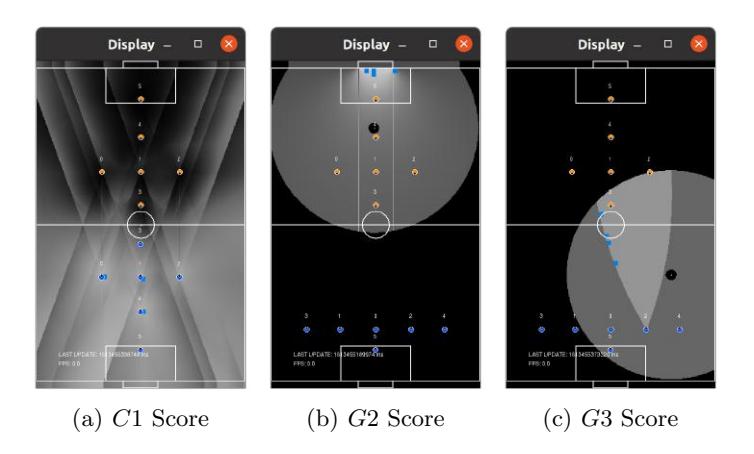
The probability is calculated as the sigmoid of the weighted sum of a list of scores, see Figure 13 for some examples. Higher C scores imply a higher probability of successfully passing to p and Higher G scores imply a higher probability of scoring a goal from p.
Those scores include:
- C1: Estimated time for the receiver to arrive at p minus minimum estimated time for any enemy to arrive at p
- C2: Minimum estimated time for any enemy to intercept between the ball and p minus estimated time for the ball to travel to p.
- C3: Penalty for p where ball traversal time is too small
- C4: Penalty for p too far from the ball
- C5: Penalty for p near defense areas
- G1: Minimum estimated time for any enemy to intercept between p and the goal minus estimated time for the ball to travel from p to the goal
- G2: Bonus for a larger open-angle from p to the goal
- G3: Bonus if p is between the receiver and the goal and does not require the receiver to rotate more than a threshold
Algorithms - Gap Probability Map
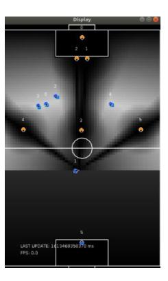
Gap Probability Map We introduced an additional probability map to calculate optimal positioning for ally robots amid the gaps of the opponent's defensive formation. The purpose of this probability map is to supplement the passing probability map described above with intelligent positioning suggestions for the remaining robots not involved in passing and receiving. Additionally, the map is used to determine the behavior of remaining robots during a get-ball tactic stage when neither side holds the ball. The probability is calculated as the product of a list of F scores; higher F scores represent higher values for interrupting the enemy and assisting the passing. Again, we refer to the position to be evaluated as p. Those scores include:
- F1: Penalty for p near defense areas, similar to C5
- F2: Penalty for being too close to opponent robots. Compute the distance d1 between the nearest opponent robot to p, set F2 = min(d1/d1max, 1.0), where d1max adjusts the size of the dark region near each opponent robot.
- F3: Bonus for hard-to-intercept region. Let line y be the line crossing p and the ball, compute the distance d2 between the position of the closest opponent robot to line y, and if that robot is within theta degree FOV of the direction of line y, set F3 = min(d2/d2max, 1.0), similar to the previous rule.
- F4: Bonus for front region close to the ball. Compute the distance b between the current evaluation point and the position of the ball, and the vertical distance f from the current evaluation point to the top of the field over the opponent side, F4 = min(b, f)/((b + f)/2).

Algorithms - Swarm Robotics
Swarm Robotics Upon having several optimal points calculated from the probability maps, the next task would be delegating a swarming group of robots to go to the optimal points. Our first approach was a naive traversal of every optimal point in order and assigns it to its nearest robot. This approach resulted in a sub-optimal total arrival time. To improve it, we changed the order of traversing the optimal points based on their relative distance to a reference point. The Optimal point closest to the reference point will be the first to assign the nearest robot, which makes the algorithm conditionally optimal depending on the choices of the reference point. Our default reference point is the center of the field, but our most frequently used reference point is actually the position of the ball, that is, the optimal points near the ball would be the first ones to get a matching robot assignment. In the future, we would like to explore the dynamic programming approach with a good global optimization measurement.
Algorithms - Moving Ball Interception
Moving Ball Interception We adopted the convenient model-free, geometrybased, and parameter-tuning based method introduced in [10] to perform the interception of a moving ball. In our implementation, this algorithm returns the next position for the intercepting robot, instead of a velocity vector as described in [10]. The reason for such implementation nuance is for taking advantage of our path finding algorithm described above with the feature of obstacle avoidance.
5.3 Decision Tree
Our AI software runs a decision tree in the main thread to direct the robots to execute a proper attack, defend, or get-ball tactic depending on situation estimation during a running game. First, when no robot has the ball, the get-ball tactic will select our nearest robot to approach and try to bring the ball to our control. Second, when the ball is under the control of our robots, an attack tactic is performed with the probability estimations running in background threads determining information regarding when and where to pass, receive, or shoot the ball, as well as where the rest of our robots should go. Our program would consider the small period in which the ball leaves the passer on its way to the receiver as the ball under our control to keep the decision tree staying at the attack stage uninterrupted. Additionally, we have implemented a simple geometry-based dodging skill for the passer to dodge away from any opponent robot while holding the ball waiting for a chance to pass. Third, when the opponent acquires the ball, a defense tactic will be executed.

5.4 Future Goals
Currently, our design relies heavily on the ssl-vision data provided by the field central camera. The ssl-vision data are susceptible to wireless communication latency and intrinsic noise. To deal with the latency, we plan to integrate a Pi Camera as both a ball detector and visual odometry. Furthermore, we plan to include an EKF algorithm mentioned in our system design to handle the noise.
The parameters for the probability maps have not yet been properly optimized, which resulted in suboptimal attack tactic performance. In addition, the current dodging skill is also over-simplified. With proper improvement with the passing and dodging skills, the attack tactic would achieve more satisfactory performance.
The robot and ball time estimators are currently trained by data collected from the simulator, which might not be ideally transferred for usage on the data collected for the physical robots. Once we are granted access to a physical lab during the pandemic later this year, we would start collecting data on the physical robots to experiment our models.
So far, the integration of ssl-game-controller and relevant auto-referee software is kept at a low priority among our development tasks. We will need to integrate them by the competition to properly experiment a virtual ssl soccer game.
6 Acknowledgements
We would not have been able to make so much progress without the RoboCup community for the extensive information put online in terms of EDTP, TDPs and GitHub repositories. We would also like to thank TIGERS Mannheim, for their extensive contributions to the RoboCup community and being advocates of open source development. Finally, a big thanks to Nicolai Ommer for his responsiveness and lending of the field camera.
We would also like to thank the UC San Diego IEEE Chapter for their support, guidance, and funding.
A special thanks is due to Professor Amy Eguchi with helping us establish contact with the RoboCup organization and helping the team grow its connections.
A special thanks is due to Professor Hanh-Phuc Le of the Electrical Engineering department at UC San Diego for his advice on power electronics and circuit control.

Acknowledgements (continued)

References
- Almagro, J., Gynai, H., Jones, T., Khadse, A., Lindbeck, C., Maisonneuve, M., Neiger, J., Osawa, R., Siqueira, A., Srinivasan, A., Stachowicz, K., Stuckey, W., Wehmeyer, C., Woodward, M., Yang, D.: Robojackets team description paper (2020)
- Barry, R., et al.: Freertos. Internet, Oct (2008)
- Bhat, M., Reddy, S., Aggarwal, S., Kirtania, A., Gupta, A., Garg, C., Roy, A., Chilukuri, G., MuraliKarthik, M., Agrawal, A., Chakraborty, D., Jindal, S., Mall, P., Aggarwal, H., Bhat, S., Kedia, K., Jodh, A., Chakraborty, A., Wadhwa, G., Agrawal, U., Ghosh, M., Mandol, S., Singh, S., Salam, T., Bhushan, M., Agarwal, S., Sinha, S., Sharma, S., Jasoria, T., Roy, A., Panda, S., Deb, A., Mukhopadhyay, J.: Kgpkubs team description paper (2020)
- Biswas, J., Mendoza, J.P., Zhu, D., Choi, B., Klee, S., Veloso, M.: Opponent-driven planning and execution for pass, attack, and defense in a multi-robot soccer team. In: Proceedings of the 2014 international conference on Autonomous agents and multi-agent systems. pp. 493–500 (2014)
- Bos, L., Citgez, Y., Dorenbos, H., Eichler, A., et al.: Roboteam twente extended team description paper 2020. RoboCup Wiki as Extended Team Description of RoboTeam Twente Team (2020)
- Dumitru, P., Ellis, G., Fink, J., Hers, B., Lew, J., MacDougall, M., Morcom, E., Sawiuk, H., Sousa, C., Dam, W., Whyte, G., Zhang, L., Zheng, S., Zhou, Y.: Ubc thunderbots team description paper (2020)
- Harabor, D., Grastien, A.: Online graph pruning for pathfinding on grid maps. In: Proceedings of the AAAI Conference on Artificial Intelligence. vol. 25 (2011)
- Kalm´ar-Nagy, T., D'Andrea, R., Ganguly, P.: Near-optimal dynamic trajectory generation and control of an omnidirectional vehicle. Robotics and Autonomous Systems 46(1), 47–64 (2004)
- Mahony, R., Hamel, T., Pflimlin, J.M.: Nonlinear complementary filters on the special orthogonal group. IEEE Transactions on automatic control 53(5), 1203–1218 (2008)
- Makarov, P.A., Yirtici, T., Akkaya, N., Aytac, E., Say, G., Burge, G., Yilmaz, B., Abiyev, R.H.: A model-free algorithm of moving ball interception by holonomic robot using geometric approach. In: Robot World Cup. pp. 166–175. Springer (2019)
- Nash, A., Daniel, K., Koenig, S., Felner, A.: Thetaˆ*: Any-angle path planning on grids. In: AAAI. vol. 7, pp. 1177–1183 (2007)
- Ryll, A., Ommer, N., Geiger, M., Jauer, M., Theis, J.: Tigers mannheim (2019)
- Sanderson, C., Curtin, R.: Armadillo: a template-based c++ library for linear algebra. Journal of Open Source Software 1(2), 26 (2016)
- Schäling, B.: The boost C++ libraries. Boris Schäling (2011)
- Stanford Artificial Intelligence Laboratory et al.: Robotic operating system, https://www.ros.org
- Yip, M.: Rapidjson: a fast json parser/generator for c++ withboth sax/dom style api (Feb 2020), https://github.com/Tencent/rapidjson/
- Yoshimoto, T., Horii, T., Mizutani, S., Iwauchi, Y., Yamada, Y., Baba, K., Zenji, S.: Op-amp 2017 team discription paper. RoboCup Soccer Small Size League (2017)