ER-Force 2022 Extended Team Description Paper
Paul Bergmann, Theresa Engelhardt, Tobias Heineken, Valentin Hopf, Michel Schmid, Mike Schmidt, Felix Schofer, Kristin Schuh, Michael Stadler
Friedrich-Alexander-Universität Erlangen-Nürnberg (FAU), Faculty of Engineering, Department of Computer Science, Distributed Systems and Operating Systems Robotics Erlangen e.V., Martensstr. 1, 91058 Erlangen, Germany
http://www.robotics-erlangen.de/
Abstract This paper presents proceedings of ER-Force, the RoboCup Small Size League team from Erlangen located at Friedrich-Alexander-University Erlangen-Nürnberg, Germany.
Introduction
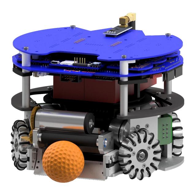
In the last years, we continued working on our new generation of robots, a process that started in 2019 [1]. In section 2, we present our new chip kick plate. Section 3 describes the redesign of our electronics circuitry. The focus lies on new board connectors, on-board documentation, our kicking circuit and a new way to cut off the battery power from our robot. In section 4, we describe changes made to our attack patterns to better handle the larger playing field. We also give an introduction into the workings of our simulator, which was used in the RoboCup of 2021, in section 5.
Mechanics: Chip Kick
The robot has two shot mechanisms: The flat kick and the chip kick. The flat kick is mainly used to pass between two robots or to score goals. The chip kick is used to shoot the ball over one or more robots and prevent them from intercepting the ball. To perform such a shot the plunger kicks against the chip kick plate, thereby lifting the ball. To reach the maximal shooting distance the ball has to follow an initial trajectory with an angle of 45°. The design of the chip kick plate is integral in determining this shot angle.
For our prior robot generation the plate was milled from a single semi-finished product. Due to the high amount of material that needed to be removed the manufacturing time and costs were excessive.
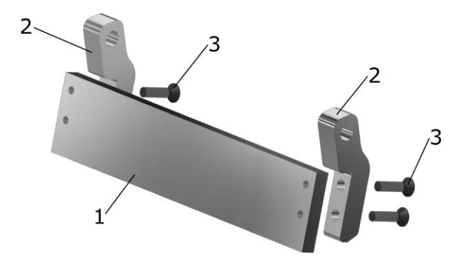
To lower the production costs, we redesigned our chip kick plate to use two-dimensional parts. These can be manufactured easily by laser cutting. The holes and threads are drilled afterwards. The new construction is shown in Figure 2. It consists of three parts: the plate in the middle (1), one panel (2) on each side and four screws (3). The panels are fixed at the back of the plate with two screws (3) each. The screws have to be placed precisely to divide the force evenly and keep the maximum strain in the panels low. Early tests showed that the torque deformed the panels after a few shots, if the screws are not positioned correctly. We successfully verified our construction in stress tests. These simplifications reduced the manufacturing time and thereby the costs decreased by 50%.
Electronics
[This section contains subsections 3.1 through 3.6, presented below]
Advantages and Disadvantages of Modularization
For the latest iteration of our electronics, we have questioned whether to reuse the modular design that we have adhered to since 2014 [2]. In this context, modular means splitting up the electronics into several parts (e.g. the motor control of each motor, the RF communication and the kicker), and then implementing those parts on separate boards instead of only having a single PCB.
As a result of our analysis, we identified the following drawbacks of the modular approach:
- Waste of Vertical Space: As many of our parts are slotted into their carrier boards vertically, the total height of the electronics increases by both the height of the male and female part of the connector as well as the height of the module itself.
- Waste of Horizontal Space: Each connection requires space on both boards for the plug or the receptacle. This space cannot be used for other components and effectively reduces the useable area.
- Expensive Electronics: Due to decentralization and the independence of our different boards, the modular design requires many connectors, ESD components and additional parts. These additional parts greatly increase the price of a robot.
- More ESD Problems: All of the single boards need to be assembled individually. This exposes more components to humans, hence increasing the risk of ESD events.
- More Firmware: Decentralization of circuitry may create the need for additional microcontrollers as it is neither feasible nor in the spirit of modularization to lead all the necessary microcontroller pins via connectors to the modules where they're needed. Hence, the increased number of MCUs leads to additional firmware work to do.
- More Assembly: As the robot consists of more boards, assembly time and the possibility for assembly errors (e.g. laterally misconnecting two connectors by a single row) is higher.
However, modularization does also have several major advantages:
• Exchangeability: If a single module ceases to function, only that module has to be swapped instead of the whole circuitry.
- Analyzability: Closely tied to the previous point, error analysis is much simpler if modules can be swapped, as one can find the broken part (e.g. when trying to flash via JTAG) by replacing the modules.
- Interchangeability: As long as modules are backwards compatible to their predecessors, both versions of the module can be used with the rest of the robot. This may ease the financial burden, as redesigns can be applied partially or only when old modules "die out".
- Solderability: Simple boards can be soldered by hand without having a high risk of failure during testing or hours of searching for solder errors. Hence, with modularization, teams can save money by soldering boards themselves.
- Divisibility: Hobbyist ECAD tools like EAGLE do have some trouble with multiple people modifying the same project files concurrently. Therefore, by splitting up a board into multiple modules, many more people can work on the same project, creating a more distributed knowledge base amongst the members of the electronics team. Besides that, as a long-time effect it can be expected that the team will have a greater workforce due to including more people.
Especially because of this last argument, we decided to keep the modularization for its advantageous effects on our members. However, even if your team decides upon sticking with a single board solution, we highly encourage you to bear in mind some modularized concepts:
- In the layout, divide your design into spatially separated modules
- Implement module boundaries (a "virtual connector") that you can open or close, e.g. by a 0R resistor or a solder bridge
- Use identical schematics and layouts for the motor controller sections
New Stackup of Electronics
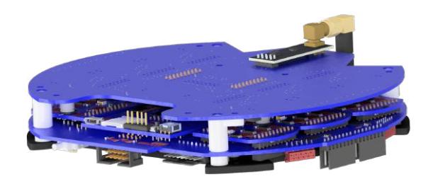
Since we chose to keep our stackup modular, we had to find a way to combat the space problem of this solution, especially when taking into account the increased size of our motors and batteries. The redesigned stackup, shown in figure 3, consists of three layers.
The bottom layer is one big PCB, the so-called power distribution board. This board provides a connection to the batteries, connects most of the other boards in terms of communication and provides power to the rest of our circuits. We also chose to place all additional connectors, e.g. to our motors, on this board to save space on other PCBs.
The middle layer holds multiple boards that each have a specific purpose for the functionality of the robot. All of these PCBs are connected vertically to the power distribution board below, saving us the space for horizontal connectors. The biggest board in this layer is our so-called mainboard. It holds our main processor to manage the RF communication and an IMU to improve the quality of our motion control. Next in line are the motorboards, that each have a processor and a motor driver installed to control one motor. In contrast to our last generation we use an separate motorboard to control our dribbler motor. The last PCB on this layer controls our new kicker circuit, described in section 3.5.
The final layer mostly consists of one board, our so called module connector. It is directly connected to the mainboard and provides slots for smaller PCBs. For the moment, we only use these slots for our antennas, but in the future we plan to add more PCBs for advanced functionalities to this layer.
New Board-to-Board Connectors
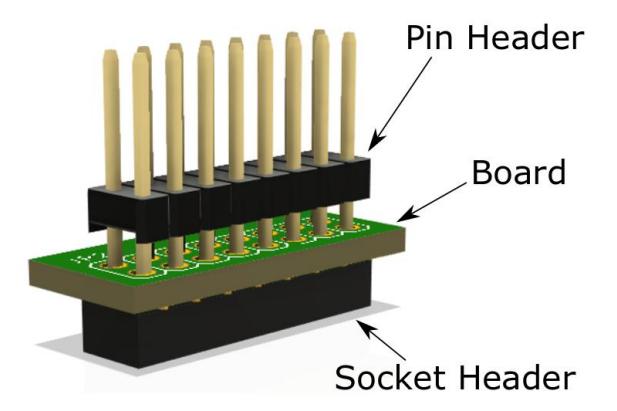
Our next step in combatting our space problem were new board-to-board connectors. As mentioned in section 3.1, we always lost a lot of vertical and horizontal space to connectors. To avoid these shortcomings, we used bottom-entry connectors from Würth Elektronik. With this technology, the plug headers are soldered to the side of the board that is opposite to the side facing the board that is to be connected. The pin header of the other board needs to be plugged into the plug header through drill holes in the PCB. This is illustrated in figure 4.
These connectors have many advantages over the top entry connectors we used before:
- Low Connector Profile: Because of their very low profile, these connectors save us a lot of vertical distance between our layers.
- No Possibility of Misalignment: Since the pin headers need to be plugged in through drill holes, it is impossible to misalign boards. This reduces the risk of errors during assembly of the robot.
- No Need for Hot Glue: Thanks to the higher contact force and the exclusively vertical connections, we no longer need to secure our board to board connections with hot glue.
Measuring Points and On-Board Documentation
With the redesign of our boards, we took the opportunity to add test pins to the boards that have enough surface area. These exposed copper surfaces facilitate the measurement of certain important signals. In earlier iterations of our boards we lacked the board surface area for test pins, which meant that we had to measure on vias or part pins, which often required us to check signals in the board documentation.
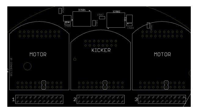
Another change we were able to make thanks to the larger board area was a proper silk layer documentation of connector layouts and part names on our power distribution board. This on-board documentation has helped us greatly since its introduction and we highly recommend it for any team. One example for a helpful addition is highlighting the connector pins used for the JTAG protocol, as shown in figure 5. Because these pins sometimes need to be bridged for flashing, it is very helpful to highlight them so we don't need to check the schematics.
New Kicker Board
Along with the redesign of our circuit boards, we decided to change the structure of our kicker hardware. In general, we use a combination of a flyback circuit, high voltage capacitors and IGBT switches to magnetize our kicker coils. In older robot generations, the flyback circuit was located in the top part of the robot while capacitors and switches were located in the bottom part.
For the new generation, we decided to bundle up all those functionalities in one single circuit board. This is supposed to reduce the impact of electro-magnetic fields emitted by the flyback circuit. Additionally, the power electronics take up a lot of space, especially the transformer. This has increased the vertical size of our electronics stackup in the past, and as such, the size of the robot as well. In the lower parts of the robot we had enough space left to house the bigger power electronics without increasing the vertical size of the robot. The new kicker is divided into low and high voltage sections. The low voltage section holds the flyback circuit, which is based on the LT3748IMS flyback controller. The high voltage section is galvanically isolated from the low voltage side and holds the capacitors, the IGBT switches and the kicker coils. The galvanic isolation is a necessary safety measure to guard the low voltage side, which is connected to the rest of our circuitry, from the high voltage in the case of an error.
This design created some new problems for our kicker circuit. First of all, the kicker is now placed in an area with a lot of EMF radiation, emitted from the motors and the flyback circuit. This radiation causes disturbances in some signals on the kicker board, among which are the input signals of our gate drivers. This lead to the destruction of some IGBTs during testing and more broad problems with the activation of our kicker. The solution was to add a low-pass filter for the gate-driver control signal.
We also conducted many tests regarding the choice of IGBT. In the end, we settled for the IRGP4066DPBF from Infineon, which is able to shoot almost 10000 times before failing. Since we did not yet have the opportunity to test our new robot as a whole as of writing this paper, we are still unsure if there will be more problems regarding EMF radiation in our robot once all the circuits operate at the same time.
New main switch for battery power
To switch our robot off, we have for the longest time used a PMOS switch between the battery output and the VCC voltage level of our robot. This worked fine for our old generation of robots because the combined voltage of our two batteries was only 16V, which allowed us to actuate the gate of the PMOS between battery voltage and ground.
Our new generation featured an increased combined battery voltage of 32V to avoid high currents when powering our more powerful motors. This voltage is too high for a typical MOSFET gate to handle, which means that the main switch needed to be actuated differently.
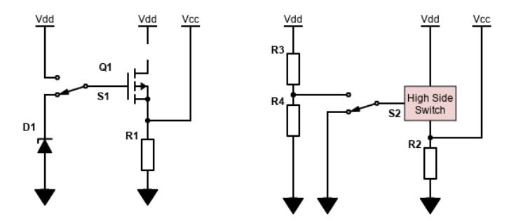
Multiple approaches to this problematic have been tested. One approach, the usage of a single battery voltage, was discarded due to the necessity of using multiple channels of a power supply during testing. The next approach consists in the usage of a Z Diode to stabilise the voltage of the gate to an acceptable level. Even though this technique works fine in testing, the high reverse current of the Z Diode cause big losses in the robot, even when it is turned off. The solution that is used in our current iteration is a smart-power high-side switch. This device consists of a N-Channel MOSFET with an integrated gate driver. It is an optimal solution in theory since N-MOS switches are generally better suited for high power applications and the integrated design meant that we could save development time and board space. However, the parts we wanted to use in our design were not easily available at online distributors, which is why this design is not yet tested by the time this paper is published.
The variants using a Z Diode and a smart-power switch are illustrated in figure 6.
Another problem encountered in our new electronics design was the residual charge of capacitors. To lessen the effect of the pulsed current required for the motors, fairly big capacitors are integrated onto our motor control boards. These hold their charge for quite a long time once the robot is turned off, which presents a major safety issue. Our solution is to fashion a discharge circuit for the VCC voltage level, which operates asynchronously to the main power switch. This discharge circuit consists of a simple NPN bipolar transistor in series with a resistor. Its base is connected to the same signal that controls the power switch, with an inverter and a RC low-pass filter for a temporal offset. This offset prevents a short circuit of the batteries in the moment of switching. This circuit was tested with an external power supply and batteries and achieves a quick discharge of any capacitors on our robot.
Objective Based Attack Coordination
As described in our 2018 ETDP [3], we use a multi-agent-based A.I. system. Agents choose a behavior that best fits the current situation. For example, an attacker could decide to duel an opponent or participate in pass planning. To reach optimal field coverage, attackers distribute themselves in zones, similar to the approach described by CMDragons [4]. To coordinate the offense, only a single main attacker is allowed to approach the ball. It will then be supported by the remaining support attackers. The support attackers strive to propose the best possible pass in their respective zones, which will then be selected by the main attacker.
When games were played 6v6 on a 6 m times 4.5 m field, we achieved favorable results by rating passes based on striker criteria. Under these criteria, passes directly leading to goal opportunities are always preferred. For example, a support attacker close to the opponent goal, standing at a good angle is valued highly. It was probable to score goals after a single pass, even if the ball started in the friendly half, since the ball traveled a large part of the field length in a short amount of time, leaving defenders little time to react.
The situation changes with the introduction of both larger fields and bigger team sizes. Longer series of passes are not only more worthwhile, they are necessary. With the ball in the friendly half, it is neither sensible nor promising to play only a single pass before attempting a goal shot. Because of this, we implemented pass ratings based on midfield criteria. Under these criteria, passes are rated highly if they advance the ball towards the opponent half and lead to good subsequent passing opportunities.
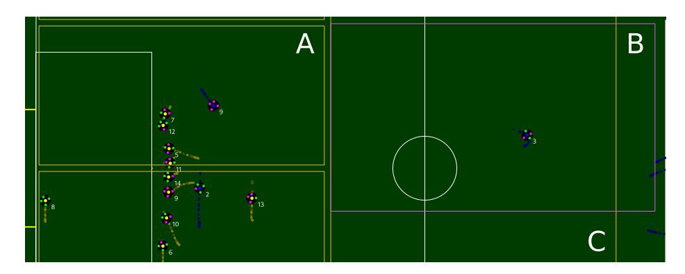
Of course, the old striker criteria are still useful in cases where we start attacks near the opponent defense area, and thus remain in use. In the initial implementation, agents were autonomous in their decision on whether to use striker or midfield criteria. If an attacker resided in the center of the field, they would use midfield criteria, while striker criteria were used near the opponent defense area. Zones were allocated independently for both midfield and striker agents. An example of criteria mismatch between different agents can be seen in Figure 7. This led to two major problems: Firstly, a lot of situations arose where the different agents would pursue different optimization targets, e.g. the main attacker would rate a pass based on midfield criteria while support attackers applied for passes using striker criteria. These criteria are not directly comparable and lead to different optimums. Secondly, it led to the attack coordination code being both hard to maintain and extend. The decision on which criterion to use was duplicated between the main and support attackers. Furthermore, care had to be taken to avoid overlap between midfield and striker zones, as the overlap would result in suboptimal field coverage, undermining the purpose of zoning.
We solve these problems by ensuring that the attacking agents always pursue the same objective. An objective denotes a common target for all attacking agents. Examples include the aforementioned cases of midfield and striker. When the midfield objective is selected, the common target is to advance the ball in the direction of the opponent half, while the striker objective aims at scoring directly. The objective determines a list of possible behaviors, pass ratings and zones for both the main and support attackers. The selection is handled centrally by the main attacker, and then announced to the remaining agents through the messaging system. Since the main attacker is the only agent allowed to handle the ball, it is a good fit for this decision. Communicating the general decision on how to proceed the attack between agents allows for easier extension of the available options and leads to fewer inconsistencies.
Having parts of the decision on how to proceed an attack coordinated centrally is in principle comparable to the play selection in an STP design [5]. It does, however, retain the flexibility of an agent based approach. Agents are free in their decision on how to pursue the objective by using different behaviors based on their local situation. They may even choose to not participate at all, e.g. because they decided to be exchanged.
For free kicks, special care has to be taken when selecting an objective. It is preferable to choose a new objective when first starting the free kick execution. Since the shooter is uncontested, it has more offensive options to choose from. After the initial selection, the currently running objective must not change for the duration of the free kick. Because of the limited timeframe, behaviors contain state depending on timing information. Since the objective determines the selected behavior, such state would be lost when switching objectives.
Simulator
Simulators play an important role in software development in the SSL, since "Simulation allows rapid testing of new code without the need to impose drain on our robotic hardware. Additionally, it allows us to simulate scenarios which we are unable to recreate" [6]. Many teams have developed their own simulators over the years [6,7,8], most notably Parsian who created the SSL-simulator grSim [9]. Since then it has been widely adopted [10,11,12,13,14,15,16,17,18]. In at least one case a team even replaced their custom simulator with it [19]. While using an existing simulator is certainly convenient and time saving, it also comes with a set of disadvantages. grSim does not fit everyones needs and other teams previously using grSim have also voiced issues with it and recently started developing their own simulators [10,11]. UBC Thunderbots decided to replace grSim with a custom 2D simulator to also simulate their firmware [10]. In our case, both the inability to embed grSim as a library and issues with its headless mode lead us to develop our own simulator.
Over the years we have implemented multiple features improving our simulator. These can be divided into two broad categories differing in what kind of aspect of reality they model:
- Physics in a perfect system: This includes things like rigid body physics and projection of balls in-flight. If any of these are missing or are notably different from reality, it is like playing with a different set of rules. This means teams have to be able to and do rely on everything in this category.
- Noise due to imperfections: This includes things like vision noise and packet loss in robot communication. If all things (camera, robots, etc.) were perfect these would not exist, but in a real game they do, because, sadly, the real world is messy. Since they vary in different situations and are important to prepare for, it is beneficial to make their simulation parametrizable.
The reliance on the first category is the reason we had concerns about using grSim as the simulator for the virtual RoboCup 2021. At the time grSim missed some important features in this category, namely projection of in-flight balls and partial and total occlusion of the ball. These would have required us and other teams to change our software to better fit grSims reality. Some of these features were later implemented, partly by our team. Instead of porting all of our features to grSim we proposed our simulator as an alternative for the RoboCup 2021. We present a more in depth look here and update our last mention from 2010 [20].
Similar to RoboTeam Twente [11] we use Bullet as our physics library, switching from ODE back in 2011. Our simulator shares most of the functionality that RoboTeam Twente mentions, namely: saving/loading situations, adjustable time scale, two-stage ball model, robot and world settings from file, simulating noise and delays, using camera parameters for parabolic flight reconstruction and convex hulls for collisions.
Simulating the Robots Our Bullet world consists of the field, the ball and the robots. Clearly the most interesting entities in this world are the robots. They are represented as a combination of a convex hull that models the main robot body without wheels and a cylinder which acts as the dribbler bar. This approach with the dribbler bar as an actual rotating rigid body does not model the dribbling behavior correctly and other teams have struggled with this as well [6], but it works well enough for our purposes. In preparation for RoboCup 2021 it turned out that this was not sufficient for other teams with better dribbling capabilities, as they lost the ball a lot more than in real games. Fixing this problem is currently not a priority for us and it would have been challenging to implement a more physically correct model that works for robots of different teams. As compromise we replaced the simulation of the dribbler bar with a mathematical constraint. This means when the dribbler is activated and the ball is close to the dribbler bar the ball gets "glued" to the robot until the dribbler stops. As previously stated the robots are modeled without the wheels and instead slide with their ground plate on the floor, but the movement of the robots is constrained to fit the possible movement of robots with omnidirectional wheels as described in [21].
The simulation also includes the communication with the robots. In reality some messages to and from the robot do not arrive, because of interference and signal strength varying over distance. In our simulator this is modeled by randomly dropping some commands and replies.
Simulating vision noise The data received from the vision software is flawed for many reasons and this can manifest in various different ways. Some detections are missing or an erroneous detection is sent, because the robot or ball was not recognized correctly, either because of bad lighting or calibration. The ball can be shadowed, making it impossible for it to be detected by the vision. Also, the detections that are sent are very noisy.
To simulate the missing detections we randomly drop a certain percentage of detections of the ball and the robots. Additionally erroneous detections close to a robot dribbler are randomly added, which in real games are sometimes caused by the light-barriers. Robot-ball-occlusion is handled by casting rays from the ball towards the camera to get the visible area of the ball. This way we can send vision data that makes it seem like the ball is moving away from the robot the more it is occluded. It will fully vanish if the visible area falls under a certain threshold.
The noise affects the detections for position, rotation and area. Each of these can be modelled with a gaussian distribution. It is obvious that rotations, area and position need different parameters, but the positions of robots and ball could be modelled with one standard deviation if the position detection of them is equally accurate. This being not the case we model robot and ball position noise with a separate parameter.
For both physical and software reasons the detections from the vision software arrive with a certain delay. This delay is modeled here with two parameters. The vision delay describes the whole delay from the point of capturing by the cameras until our system receives it. The processing time describes the delay caused by the vision software. This is useful because that means that the time stamp for when the frame was captured is simulatortime + visiondelay − processingtime. The detections will be sent at time simulatortime + visiondelay + jitter.
High-Level Features The simulator is completely integrated with the rest of our open-source framework. This makes testing with it very convenient as we can manipulate the simulation from the UI, e.g. by moving the ball with the mouse, and quickly switch to the logplayer and back to the simulator without leaving the application. It might even allow us mix log playback and simulation to add robots recorded in a log into the simulation in the future.
Internally the simulator acts as a complete SSL-Vision replacement and sends the same data one would receive in a normal game. For external use it can also be run as a CLI that accepts the new SSL simulation protocol, as has been done during the RoboCup 2021. The protocol is currently only implemented by grSim and our simulator, but we hope this shared interface encourages other teams to share their simulators, too.
To make it simpler to test in different environments it is possible to create and use a preset. The default ones provided with our framework are Realistic, RC2021 and None. The preset None allows for simple prototyping of new functions without immediately having to deal with real world problems, by disabling all noise. The parameters from the Realistic preset were measured using the logs from RoboCup 2019, so they approximate a real environment as close as possible. The RC2021 Preset is a compromise for use in last years RoboCup, reducing noise a bit compared to the Realistic preset. The realism provided by our simulator is obviously not perfect, but has allowed us to develop our A.I. almost completely in the simulator and mostly only having to tweak parameters when testing with real robots.
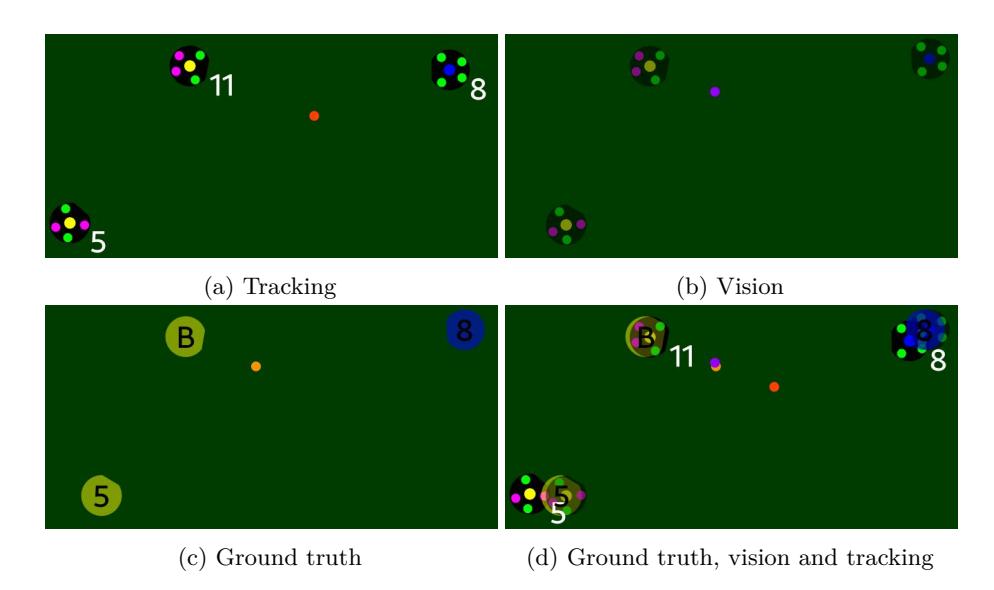
It additionally has the advantage over tests with real robots that we can visualize the simulator ground truth. See Figure 8 on how these different sources are visualized. The ground truth is really useful to figure out where something went wrong, for example if the problem is in the tracking or the strategy or why the ball is invisible at a certain point.
References
- Engelhardt, T., Heineken, T., Kühn, T., Lindner, J., Schmidt, M., Schofer, F., Seifert, C., Stadler, M., Wegmann, L., Wendler, A.: ER-Force 2019 Extended Team Description Paper. (2019)
- Bayerlein, H., Danzer, A., Eischer, M., Hauck, A., Markus Hoffmann, P.K., Lieret, M.: ER-Force Extended Team Description Paper RoboCup 2014. (2014)
- Lobmeier, C., Burk, D., Wendler, A., Eskofier, B.M.: ER-Force Extended Team Description Paper RoboCup 2018. (2018)
- Mendoza, J.P., Biswas, J., Zhu, D., Wang, R., Cooksey, P., Klee, S., Veloso, M.: CMDragons 2016 Extended Team Description Paper. (2016)
- Browning, B., Bruce, J., Bowling, M., Veloso, M.: STP: Skills, tactics and plays for multi-robot control in adversarial environments. Journal of Systems and Control Engineering 219(1) (2005) 33–52
- Zickler, S., Bruce, J., Biswas, J., Licitra, M., Veloso, M.: CMDragons 2009 Extended Team Description Paper. (2009)
- Perun, B., Ryll, A., Leinemann, G., Birkenkampf, P., König, C., Berthold, G., Scheidel, S.: Tigers Mannheim (Team Interacting and Game Evolving Robots) Team Description for RoboCup 2011. (2011)
- Cunningham, A., Posey, S., Johnson, B., Borissov, S., Gendreau, A., Mitchell, N.: RoboJackets 2011 Team Description Paper. (2011)
- Monajjemi, V., Koochakzadeh, A., Ghidary, S.S.: grsim - robocup small size robot soccer simulator. In: RoboCup. (2011)
- Dumitru, P., Ellis, G., Fink, J., Hers, B., Lew, J., MacDougall, M., Morcom, E., Sawiuk, H., Sousa, C., Dam, W.V., Whyte, G., Zhang, L., Zheng, S., Zhou, Y.: 2020 Team Description Paper: UBC Thunderbots. (2020)
- Bos, L., Citgez, Y., Dorenbos, H., Eichler, A., van der Hulst, R., Nagelvoort, L.K., van der Kuil, T., Luong, J., Poort, L., Prinsenberg, F., de Regt, C., Uiterkamp, L.S., Schrijver, R., Steerneman, E., Vacariu, P., van Werven, J., van der Werff, S., Zwerver, S.: RoboTeam Twente Extended Team Description Paper 2020. (2020)
- Silva, C., Alves, C., Martins, F., Machado, J.G., Damurie, J., Cavalcanti, L., Vinícius, M., Sousa, R., Rodrigues, R., Fernandes, R., Morais, R., Araújo, V., Silva, W., Barros, E., Bassani, H.F., de Mattos Neto, P.S.G., Ren, T.I.: RobôCIn 2020 Team Description Paper. (2020)
- Allali, J., Bezamat, J., Felix, P., Loty, S., Mignot, V., Muller, X., Pigret-Cadou, R., Saliba, T., Schmitz, E.: NAMeC - Team Description Paper Small Size League RoboCup 2020 Application of Qualification in Division B. (2020)
- Bhat, M., Reddy, S., Aggarwal, S., Kirtania, A., Gupta, A., Garg, C., Roy, A., Chilukuri, G.R., Karthik, M., Agrawal, A., Chakraborty, D., Jindal, S., Mall, P., Aggarwal, H., Bhat, S., Kedia, K., Jodh, A.S., Chakraborty, A., Wadhwa, G., Agrawal, U., Ghosh, M., Mandol, S., Singh, S., Salam, T., Bhushan, M., Agarwal, S., Sinha, S., Sharma, S., Jasoria, T., Roy, A., Panda, S.K., Deb, A.K., Mukhopadhyay, J.: KgpKubs 2020 Team Description Paper. (2020)
- Naito, Y., Ohno, S., Imaeda, Y., Odanaka, A., Tsuruta, Y., Mitsuoka, R., Tane, T., Watanabe, M., Sugiura, T.: KIKS Extended Team Description for RoboCup 2020. (2020)
- de Oliveira, G.P., Alves, V.M., Pilotto, D., de S. Motta, W., da S. Costa, L., Pauli, G.L., Laureano, M.A.P., Cadamuro, C.A.F., Bianchi, R.A.C., Junior, P.T.A., Tonidandel, F.: RoboFEI 2019 Team Description Paper. (2019)
- Huang, Z., Chen, L., Li, J., Yunkai Wang1, Z.C., Wen, L., Gu, J., Hu, P., Xiong, R.: ZJUNlict Extended Team Description Paper for RoboCup 2019. (2019)
- Barcelos, A.O.P., Segre, J.L.L., de Lima, L.O., Barreira, N.A.F., Gemignani, R., Filho, R.C.M.B., Betio, V.H.F., Bramigk, V., Rosa, P.F.F.: RoboIME: on the road to RoboCup 2014. (2014)
- Budanov, D., Feltracco, J., Kamat, J., Medrano, R., Naeem, S., Neiger, J., Osawa, R., Pan, M., Peterson, E., Shaw, A., Stuckey, W., Ting, J., Woodward, M.: RoboJackets 2017 Team Description Paper. (2017)
- Blank, P., Bleier, M., Kallwies, J., Kugler, P., Lahmann, D., Nordhus, P., Riess, C.: ER-Force Team Description Paper for RoboCup 2010. (2010)
- Purwin, O., D'Andrea, R.: Trajectory generation for four wheeled omnidirectional vehicles. In: Proceedings of the 2005, American Control Conference, 2005. (2005) 4979–4984 vol. 7