luhbots Soccer Team Description for RoboCup 2022
Larissa Seegemann, Fabrice Zeug, Patrick Ebbighausen, Lukas Waldhoff, Timo de Vries, Mira Sukkar, Max Känner, Jan Ole Weber
Institute of Automatic Control Gottfried Wilhelm Leibniz University Hannover Appelstr. 11, 30167 Hannover, Germany
Abstract This paper describes the luhbots Soccer team and its autonomous football players. This is the initial team description which is a prerequisite for competition in the RoboCup Soccer Small Size League. Given that this team is entering the competition for the first time, we discuss primarily the hardware, electrical design as well as the applied software.
Introduction
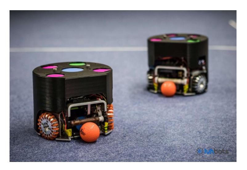
We, the robotics team of the Leibniz University Hannover, have been developing our current robot generation (as seen in figure 1) since the winter of 2019. Since then our team has gained a lot of popularity leading to a significant increase in new members. This has expanded our knowledge-base considerably. In just the past few months we have made major developments in our hardware and electronics. These technical advances are now at a level in which we are ready to compete in a tournament.
Our group consists of undergraduates from several different fields such as, electrical, mechatronical, mechanical engineering, computer science and computer engineering. Branching off from the RoboCup@Work league, we were (and are) given a great deal of support by our university and its institutes. This financial, as well as educational assistance enables us to realize our ideas in real time. We are highly motivated by our curiosity and passion for taking on new challenges. Existing teams, such as TIGERs Mannheim, and open-source code-bases have helped us gain a stable foothold in the field and its technical challenges. The first generation of robots is nearly complete and we are eager to compete with them in the Division B of the Small Size League.
Mechanics
The goal of our first generation of robots (see figure 1) was implementing the basic functions such as kicking, dribbling and driving. We focused mainly on these three skills during development of the robots. In the mechanical design attention was paid to assure quick assembly and a resource-optimized production. Additionally we wanted to increase the stability of the robot. This is why we decided to design a completely new base plate, independent from the designs of other teams. We based our first hardware drafts on the design from the open source model of the TIGERs Mannheim [2].
Table 1: Specifications of robot generation 1
| Ø178mm x 145mm |
|---|
| 2,33kg |
| 22,2V (6S LiPo Battery) |
| Nanotec DF45L024048-A2 65W |
| TMC4671 |
| none |
| 61mm |
| omnidirectional |
| T-MOTOR BLACK BIRD V2.0 1950KV |
| 24:19 |
| 12mm |
| silicone |
| 1.36mF @350V |
| $5.3 \mathrm{m/s}$ |
General Design
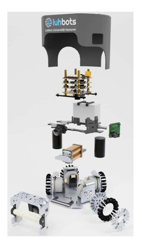
Most of the essential components, such as the four omnidirectional wheels, the dribbler and the kicker are placed directly onto the base plate. On top of which there is a plastic frame fixed to position the electrical system boards. The Boards are placed on top of each other building a stack. The installation of the drive motors on the base plate is explained in more detail in section 2.2.
Base plate
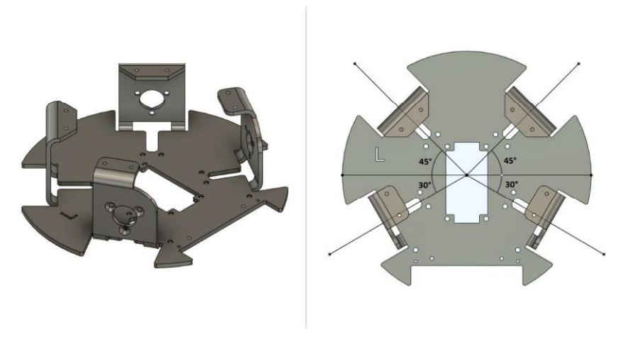
The basic shape of the base plate is comparable to that of other teams, due to the general conditions that have to be met according to the RoboCup SSL guidelines. But what makes ours special is that the base plate and motor mount are made from a single piece of sheet metal.
With this implementation, we have the advantage of not needing additional holes for screws in the base plate which increases stability. In addition, the first level can be attached to the motor mounts which creates a very compact system. Of course, this design is a lot more complicated to manufacture than a flat plate with external elements on it, but the advantages outweigh the disadvantages.
Figure 3 shows the current base plate and the position of the motors in relation to one another. Noticeably, the angles between the wheels are not equal, making smooth movement in certain directions difficult - mainly the sideways motion. Unfortunately, shifting the wheels to another angle is not possible with the current generation of robots.
Drive train
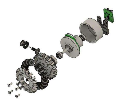
To enable movement in every desired direction, we, as do other teams in the Small Size League[2], use omnidirectional wheels. Our basic design deviates only slightly (see Figure 4). The main difference is the attachment of the wheel to the motor shaft.
In order to enable quick assembly with optimal torque transmission, we chose to mount a hub on the motor shaft, which is comparable to the wheel hub of a car. The wheel can be attached to the hub with four screws. To incorporate speed and angle detection an external encoder is mounted to the base plate. To power the wheels we use a brushless DC motor (Nanotec DF45L024048-A2).
Dribbler
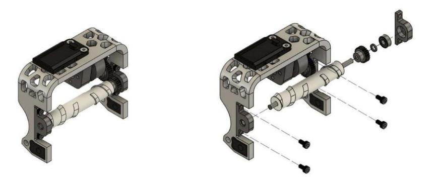
Essential for the ball control is the dribbling mechanism, which is shown in figure 5. It allows the robot to move in every direction without losing the ball. For this, the choice of shape and material for the roller is of crucial importance. In the following section, the individual core elements of the dribbler will be discussed in more detail.
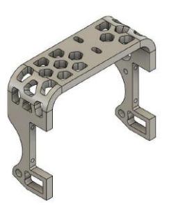
Contrary to other teams, our dribbler body consists of a bent sheet of metal, which was cut by a laser cutter. The current dribbler design is depicted in figure 6. This design not only ensures high stability, but allows quick assembly and disassembly of the dribbler. Because of the additional bearing holders for the roller, we are able to exchange a defective roller without dismantling the whole dribbler body.
To absorb the momentum of the ball, the dribbler body is connected in a tiltable fashion onto the base plate and damped by a 3D printed part made of flexible filament. On each side of the dribbler are also 3D printed inserts for the light barrier, which detects the dribbling of the ball and enables fast reactions.
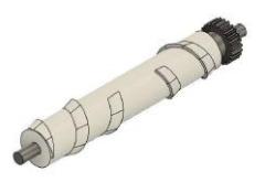
Figure 7 shows the current design of the roller used in our robot. The shape is inspired by the teams TIGERs Mannheim and ZJUNlict and was adapted to our specific needs [2, 3]. It is characterized by the fact that it centers the ball constantly, due to its geometric features. To manufacture the roller, silicone is injected into a 3D printed mold containing a 4mm thick rod. We chose silicone over polyurethane, because it is more flexible and much cheaper. Due to these properties, we achieve particularly good traction between the ball and the robot with minimal use of resources.
In order to connect the roller to the motor, a 24-tooth gear wheel is glued directly onto the roller's rod. It is linked to a 19-tooth gear screwed onto the motor shaft, by a 35-tooth gear between them. This linking gear is positioned on a small ball bearing mounted onto the dribbler's inside wall. All gears are made of polyacetal.
We use the drone motor Black Bird V2 1950KV from T-Motor to drive the dribbler roller. This motor allows us optimal ball control because of its high number of revolutions and is comparatively cheap.
Future work
One of our next steps is to work on improving the drive system by changing the angles between the wheels to equal 90 degree angles. This change will cause a smoother movement in almost every direction which will subsequently enhance the overall performance.
Additionally, we want to implement a chip kicker to the existing kicker (which will be discussed in more detail in section 3.2), so it would have the ability to chip the ball. Adding this feature is going to give the robot the ability to remove the ball from critical situations, such as facing an enemy in close proximity.
Electronics
ESCs
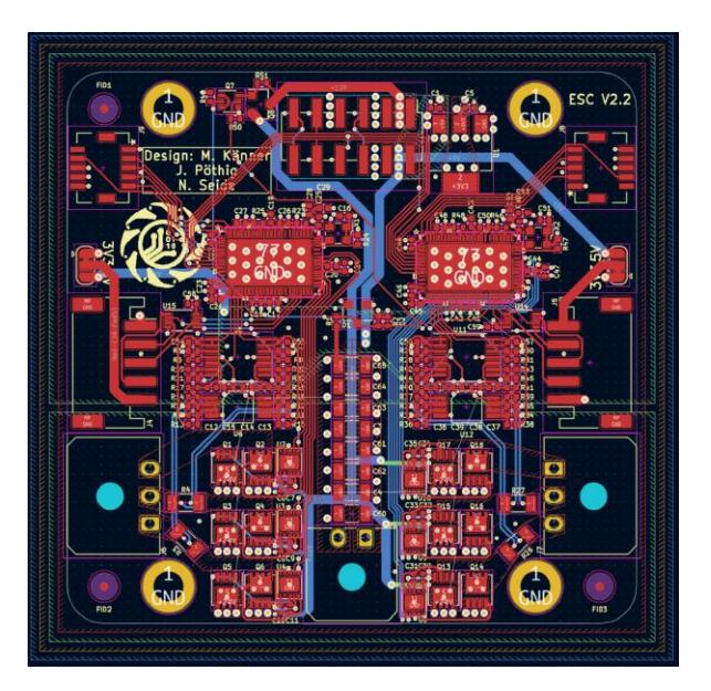
The Electronic Speed Controllers (ESCs) are designed around the TMC4671 motor controller. Each ESC communicates over an SPI Bus with the main control board. All the necessary wiring, except for the battery voltage, is routed through a 0.2" board interconnect. The TMC4671 uses Field Oriented Control (FOC) to regulate the motor. Control loops for torque, velocity and position are implemented on the TMC4671 to reduce the load on the main processor. FOC requires accurate feedback from the motor, so we decided to use an incremental magnetic encoder to measure the motor position. Our ESC layout is depicted in figure 8.
The motor coils are driven by discrete high power MOSFETs. This is to make sure they can handle the current flowing through the motor coils. Electrical current measurements are required to be inline with the motor coils. This means there cannot be a stable voltage potential at either side of the shunt resistor complicating the measurement. Measurement of electrical current is done in two stages. In stage one the common voltage is removed by a differential amplifier. This requires precisely matched resistors to reject any common mode pwm signals. At the second stage the signal is amplified to range from 0V to 5V so it can be measured by the TMC4671. In between the first and second stage a filter
is inserted to aid in removing the common mode signal. However, a filter removing all of the common mode, using our current setup, would also filter other important information and thus not be a useful implementation. The ESCs are designed to be stacked on top of each other with the main board at the top of the stack (see figure 2). Each PCB contains two ESCs to make the stack smaller.
Kicker
For the kicker, an electromagnetic coil design was preferred over a spring-based shooting mechanism. Different variants were simulated in FEMM for both the coil and the bolt. For the coil, 0.5mm thick copper wire was chosen and wound in 6 layers. An iron rod core is used as the piston. The piston is pulled back by two rubber bands, that are glued to the upper deck. A flyback transformer, based on an LT3751 chip, transforms the battery voltage to an adjustable voltage up to a maximum of 440 volts. The components were selected so that this voltage can be reached in less than a second, allowing fast execution of passes. Unlike most reference designs [1], a Schottky diode is used as the main output diode, as this has no reverse recovery time, which should slightly increase efficiency.
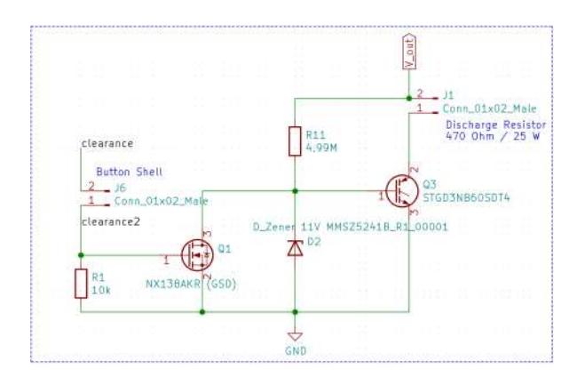
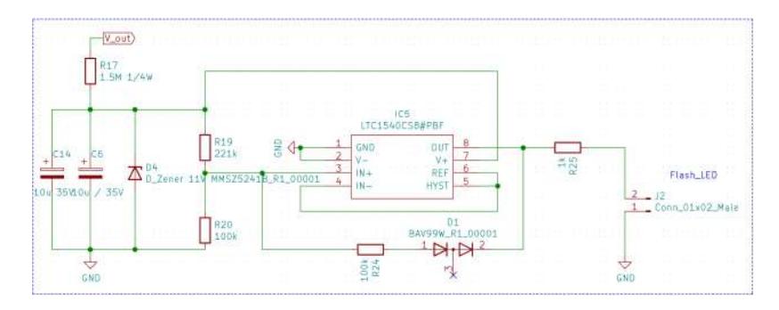
Normally, the voltage is limited to well below 440 volts and further measures have been taken to prevent danger to humans. A discharge circuit (see figure 9) was implemented which immediately discharges the capacitors through a resistor once the supply voltage is removed. A button is attached to the housing, without which charging is impossible and which also leads to immediate discharging when the robot is opened. Furthermore, a clearance signal must be given in the software so that the kicker can charge in the first place. In addition, there is an LED mounted onto the housing that flashes depending on the charging state and thus warns humans of dangerous voltage. The LED flashing circuit is powered by the capacitors and is therefore independent from the battery (figure 10). A distribution board was designed to connect the charging circuit with the capacitors and the coil. This board also contains the IGBTs for kicking and is galvanically isolated from the rest of the control-electronics. The kicking strength is adjusted by the pulse width given on the IGBT gate.
Mainboard
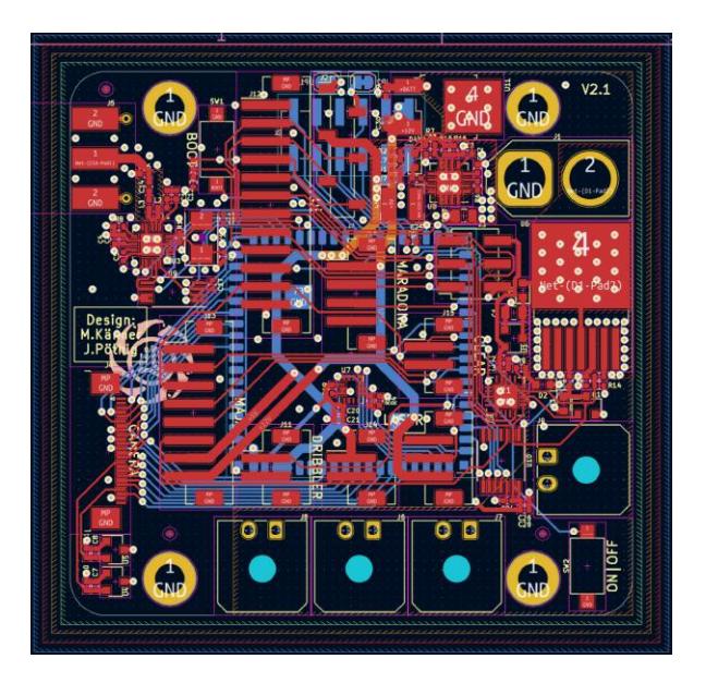
The mainboard's job is to generate and distribute voltages, as well as controlling the electronic systems and communicating with the server. Our mainboard layout is depicted in figure 11. The battery voltage (18V - 25.2V) is distributed to all high power components, namely the ESCs, the kicker and the dribbler. A 5V and 12V potential is generated from the battery voltage and distributed to the other electronic components. A small microcontroller is used to switch the battery voltage using a smartFET and monitors the voltage to make sure the battery is not overly drained.
As a main controller a Kendryte K210 RISC-V processor is used. The processor communicates with the server over a $2.4 \mathrm{GHz}$ radio frequency using nRF24L01 transceivers. The motion of the robot is captured using an internal measurement
unit which is used to improve the position estimation of the robot. A camera can be connected to the mainboard for enhanced ball tracking.
Future work
We plan to improve the integration of the kicker into the stack by routing the necessary connections through 0.2" board interconnects. This would also allow the enhancement of the ESCs by using a dedicated current amplifier chip instead of the cascading op-amp circuit we use now.
Software
The software of the luhbots soccer team is based on ROS (Robot Operating System) [4]. Its structure enables us to divide the existing tasks into separate nodes, which can be then developed independently by different team members. ROS offers a variety of tools and frameworks, which are generally very useful for mobile robotics. Especially the tf (transform) package [6] and the parameter server [5] are used quite often in our team.
Most of the calculations and decisions are made by the ROS system, which runs on a separate server. Nevertheless, the robots themselves have a Kendryte-Module each, including firmware. Since the server makes most of the necessary decisions, the robots mainly only execute the commands sent by the server and give feedback in return. In contrast to all communication taking place on the server itself, the communication to the robots is not realized with ROS messages, but with self written packages sent via a 2.4GHz UDP connection.
The software is divided into two major parts: strategy and robot control. The strategy section assigns Skills to each robot, which are then executed by the robot control component. The robots themselves receive specific velocity commands at any time.
Strategy
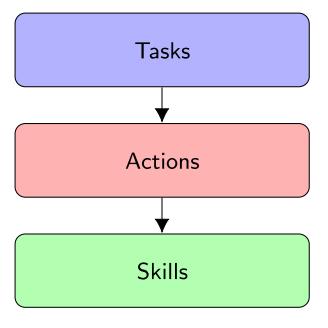
If we break down the complex decision making process of our program, we are left with a layer model containing 3 major levels: Tasks, Actions and Skills. This model is displayed in figure 12.
Three archives saved as yaml files provide a collection of Skills, Actions and Tasks. These libraries can be filled and altered continuously during the programming process. A threat level evaluator is positioned at the top of the decision
making procedure. The evaluator assigns one of two roles to each robot: defense and offense. Taking into consideration the current threat level, game status and our team's capabilities, the program then chooses an abstract Task that needs to be achieved. This Task, for example "defend goal", can be fulfilled by a set of Actions which need to be chosen. To choose an assembly of Actions from the archive is the assignment of our artificial intelligence which still needs to be implemented. Certain Actions that might fulfill the "defend goal" Task include: "mark enemy", "intercept pass", "intercept dribbling path", .... The last step connecting the Action archive to the Skill archive is simple, since every Action requires a set of preset Skills. Because every Skill might be needed by several Actions, we decided on making a separate archive for the Skills. Looking at the Action example "mark enemy" the Skill required is as follows: "position continuously on intersection of line between goal and enemy and radius around enemy. Rotation towards enemy".
Robot Control
The main component of the robot control is the local planner. Since the environment is relatively simplistic, we decided to combine the traditional global planner with the local planner in our approach. The path-planning is skipped and the local planner receives the global goal. The goal for a robot can be more complex than just driving to a given point. For example, the Skill to always position oneself between the enemy robot and the ball, in order to block a pass, would require to constantly send new goal points and, more importantly, calculate the position of these points. Because of that, the local planner receives its goals not in form of points, but in Features. A Feature is described by a type, a shape and coordinates. Depending on its type, the Feature influences the robot's movements. Possible types are "Goal", "Robot" and "Border" Features. In addition to the described properties, a Feature can be defined as dynamic or static. Besides the coordinates, a ROS transform frame has to be given, in that case. If the frame is moved, the points in that frame are moved as well. This is used, when the position of the goal is not fixed and can change with time (for example to react on the enemy robots movement).
Goal Features, as the name suggests, are goals for the robot's movement. The local planner tries to minimize the distance to all given goals, at any time, in driving mode. Robot Features mark other robots, allies as well as enemies. Border Features mark the borders of the soccer field, including the defense area. The sum of the Features' influences is used as a velocity command for the robots.
Determining the influence of Feature At first, the direction to the shortest point in a given Feature and the distance d to that point is calculated. Depending on the distance and the type, a multiplier for that feature is calculated.
The multiplier of goal Features for example is based on the distance needed to bring a vehicle with a given velocity to a full stop. The distance is proportional to the square of the velocity, which leads to the equation 1. This equation calculates the maximum velocity for the robot to move toward its goal, if no other Features influence the robot. The constant $k_2$ in this equation has to be determined experimentally.
$$d_{stop} = k_1 \cdot v^2 \Leftrightarrow v = \sqrt{\frac{d_{stop}}{k_1}} \Leftrightarrow v = \sqrt{d_{stop}} \cdot k_2 = m, \quad k_2 = \sqrt{\frac{1}{k_1}}, \quad k_2 = const.$$
Future Work
The main upcoming implementation we want to realize, is our artificial intelligence. It is supposed to decide independently which tasks and Actions are to be chosen, in order to fulfill our main goal: Winning the game.
Acknowledgements
Special thanks to our supporting institutes. The Institute of Automatic Control (irt) and Institute of Mechatronic Systems (imes). We appreciate the financial and educational support and are lucky to have a team that believes in us. We also want to specifically thank the team TIGERs Mannheim for their time to discuss our initial designs and software ideas. We have learned a lot from the tips given and tried to implement them as best we could into our first robot generation. We are grateful to be part of a university supporting several different student associations. This allows us to exchange interdisciplinary ideas and share our respective technical inventories.
References
- Analog Devices LT3751 datasheet, https://www.analog.com/media/en/technical-documentation/data-sheets/LT3751.pdf. Last accessed 28. Jan 2022
- CAD model, Mannheim TIGERs, https://github.com/TIGERs-Mannheim/mechanics. Last accessed 26 Jan 2022
- CAD model, ZJUNlict, https://github.com/ZJUNlict/Mechanics. Last accessed 26 Jan 2022
- ROS Homepage, https://www.ros.org/. Last accessed 19 Jan 2022
- ROS Parameter Server, http://wiki.ros.org/Parameter%20Server. Last accessed 19 Jan 2022
- ROS tf package, http://wiki.ros.org/tf. Last accessed 19 Jan 2022