NEUIslanders Team Description Paper RoboCup 2022
Prof. Dr. Rahib H. ABIYEV, Nurullah AKKAYA, Tolga YIRTICI, Ersin AYTAC, Gokhan BURGE, Sanan ABIZADA, Ali TURK, Gorkem SAY
NEU Robotics Lab., Department of Computer Engineering, Department of Electrical and Electronics Engineering, Department of Mechanical Engineering, Near East University (NEU) Lefkosa, Turkish Republic of Northern Cyprus
Abstract NEUIslanders team has been participating at RoboCup Small Size League since 2012-present. Four years ago in Montreal, Canada NEUIslanders team became SSL Division B champion. This paper presents in detail how the NEUIslanders team made improvements in their robots and AI from the past years.
Introduction
NEUIslanders is a robotics football team. It was developed by the Near East University (NEU) robotics lab. The NEUIslanders team competes in the Small Sized League (SSL). This team has been participating in RoboCup since 2012. The team consists of undergraduate and graduate students. The team has researchers who contribute in different areas. NEUIslanders team was the 2018 champion in Division B, Canada, and placed 3rd in the 2016 European Open. This year, several improvements and adjustments were made to the robots. The NEUIslanders software team made several improvements to the robot's software. The codes and firmware have been updated. New control algorithms were proposed for the robot's BLDC motor wheel and dribbler mechanisms. The electronics team developed a new circuit for the controller. The sinusoidal controller used for the BLDC motor was outlined. The mentioned changes are shown below.
DC Motor Control Algorithm
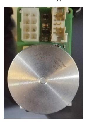
A new controller for the robots was implemented to control the wheel motors. At low speeds, the wheel motors have ripples that should be eliminated. During the game, the rotation of the wheels should be smooth so that the wheels can move properly on the playing field. To achieve smoother rotation of the wheel motors, more precise control is required. To eliminate this ripple and achieve control of the BLDC motor, a sinusoidal control algorithm is demonstrated. Sinusoidal commutation produces smooth drive and precise motor control. Therefore, proper commutation results in proper switching sequence of the switches. To apply the control method, some parameters are required: the rotor position and the mechanism of commutation. First, the BLDC motor controller detects the position of the rotor using sensors (the motors that robots use have the hall-effect sensor). The sensor detects the position of the rotor by measuring and sending the information. The controller uses this information and enables transistors. The transistors switch ON and OFF the switches so that the direction of the current from the switches energizes the stators at the right time. Six-step (six transistors) commutation is required to create a circuit to energize the stators for the three-phase BLDC controller. The position of the rotor can be measured by several methods. It can be measured with a sensor and without a sensor. The sensored method is used because the wheel motors that robots use have Hall effect sensors. The motor of the wheel can be seen in Figure 1.
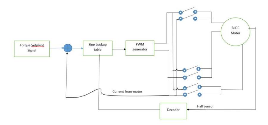
Several methods can be applied to the BLDC controller. Sinusoidal control provides much smoother control at lower speeds. Therefore, sinusoidal control is chosen. By obtaining a constant magnitude, the torque ripple spikes that occur during commutation are eliminated. To change the direction of the current to the magnetization of the stator, a MOSFET is used. In other BLDC control applications where this is required, high power switches called IGBTs and GaN can replace the MOSFETs. The sinusoidal drive method uses pulse width modulation (PWM) so that commutation can be operated and current flow is controlled more smoothly. PWM technique is a powerful technique to control BLDC. The output of the feedback input is varied by changing the PWM width. Thus, by changing the PWM duty cycles sinusoidal waves are obtained [4]. The PWM switching frequency depends on the BLDC controller and the microcontroller. However, initially Hall effect sensors are used to collect data about BLDC rotor positions [2-3]. Therefore, the current will flow correctly at the right time. Using the commutation logic and the sine wave lookup table, the PWM is generated. The windings in the stator are spaced 120 degrees apart. The sinusoidal look-up table is aimed to provide signals to generate the sinusoidal phase current of the motor to achieve proper commutation. The block diagram of the sinusoidal motor controller is shown in Figure 2.
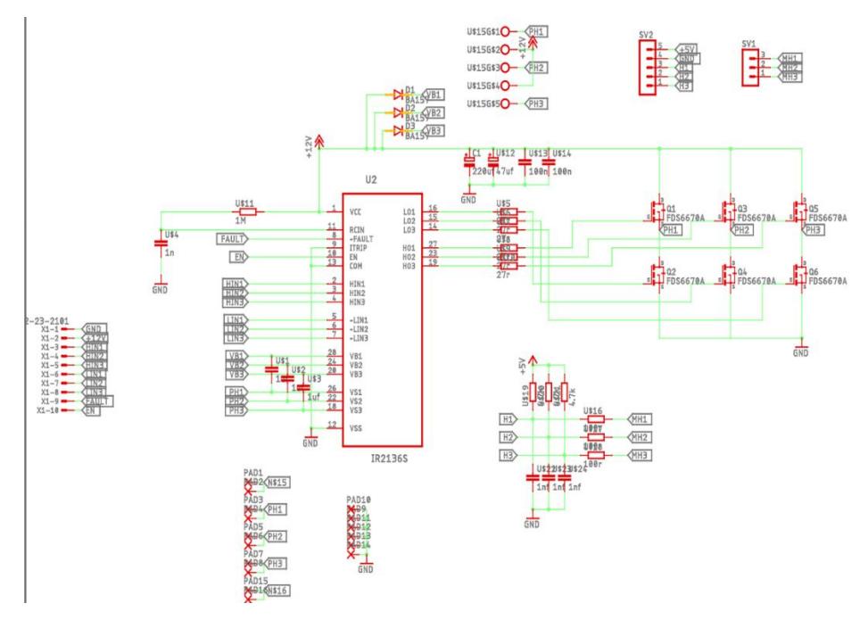
Matlab Simulink is used to design and simulate the circuit. The Simulink model is exported to Matlab code to generate the code of the model. Figure 3 shows the sinusoidal controller circuit schematic.
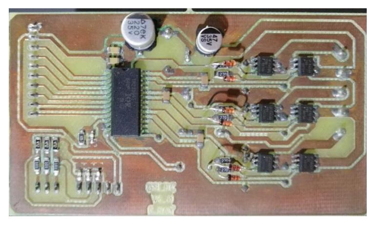
The electronics team developed a BLDC motor controller circuit to implement a Sinusoidal control algorithm. IR2136x MOSFET driver [1] is used for the operation of the MOSFET. These drivers are high-speed and high voltage drivers for 3-phase applications. Atmega328P is used for the microcontroller. The PCB of the BLDC motor control circuit is shown in Figure 4.
Software
A number of improvements have been made to the software. The improvements include programming language conversion, firmware updates, pathfinding changes, and a new hardware designed for communication purposes. Below detailed explanations can be found.
The robot's software is designed in such a way that it consists of multiple programming languages. The C++ programming language is used for firmware, the Clojure programming language is used for decision making, and there are several Matlab modules for filters such as Kalman filtering, vision filtering, etc. With the new design, this was changed and the Matlab dependency was removed. The reason for this was two-fold. First, it was necessary to get rid of the Matlab runtime dependency which is quite large in size, and the native code is required for the filters for performance reasons.
Matlab modules are used for the vision filters and ball interception algorithms. Both of them always run in tight loops. To improve performance and allow the code to run on platforms such as arm64 that does not support Matlab, all Matlab modules are compiled into C libraries using Matlab Coder. These are then either compiled into shared libraries on target platforms that are running with an OS or embedded into other source files when compiling for microcontrollers. This scheme removed the dependency on Matlab runtime. This was also a requirement for building a communication box, since it runs on hardware not supported by the Matlab runtime.
The old system used RRT path finding and fuzzy obstacle avoidance. The decisionmaking system switched between the two based on the distance to the target location. For long-distance travel, RRT is used for calculating a collision-free path to target but once the robot gets close to the target location, the decision-making system switched to obstacle avoidance mode since the robot is almost at the target location calculating RRT can be avoided and instead obstacle avoidance can be used since it is much cheaper to calculate.
In the new design, a new interface has been created that allows additional pathfinding algorithms to be added to the system. This interface combined with a behavior tree-based decision-making system [6] allows much more complex navigation logic to be implemented and allows the team to easily experiment with new path-finding algorithms with very little modification to the decision-making code. In addition to old RRT and Fuzzy obstacle avoidance-based navigation methods, the team has experimented with the A* algorithm and Potential Field methods as well.
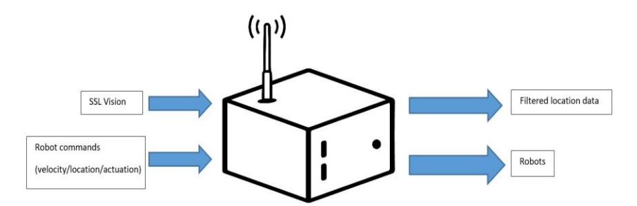
Often, the colleagues in the respective departments wanted to use the robots for research purposes. This poses a problem since someone who knows the system and the platform (The decision-making system is written in Clojure which is a Lisp dialect that runs on the JVM) needs to be present in order to run the programs. To overcome this problem, the so-called communication box is developed.
The communication box is basically a Raspberry PI, which receives vision data from SSL-Vision, runs the ball and robot tracking filters, and rebroadcasts the clean filtered data just like SSL-Vision on a different port. Since SSL-Vision uses Google Protobuf which has bindings for all major programming languages any programming language can receive clean filtered robot location data without knowing the inner workings of SSL-Vision and the vision hardware used. Once the location data is provided the next step is allowing the control of the robots. The communication box can also receive velocity, location, or actuation commands using Google protobuf, allowing all surfaces of the robot to be controlled. It handles all low-level control aspects such as running PID loops for velocity control. So researchers can focus on high-level research without having to deal with low-level control, which is already a solved problem in the system. Another advantage of this system is that, during the competition depending on where the PC that runs the robot's program is located and on which side the robots are playing, some combinations provide very poor RF reception which hinders communication with the robots.
The communication with the box is provided via Ethernet so it can be placed in an optimal position that maximizes the RF reception while keeping the PC at the desk away from the communication box. The communication box can be seen in Figure 5.
Mechanical Design
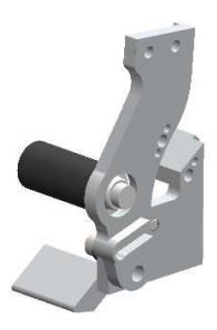
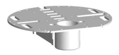
As in previous years, two major mechanical changes were made to the Islanders' robots this year. First, the kicking mechanism was previously made of iron. Since the other components of this mechanism were also made of iron, problems arose during kicking, and the part that enables the chip kick stuck to the chassis of the Islander robots. Because of this, there were delays and stutters while the robot kicked the ball. This year, the components of the kicking mechanism were made of aluminum instead of iron. In 2020 and 2021, research and development studies focused on the problems of the kicking mechanism. It was revised and tested using additive manufacturing technology. Then, the kicking mechanism was made of polylactic acid (PLA) [5], a thermoplastic material class, and Islanders participated in the competition. It was realized that these studies were successful in the competition, but since the mechanism was made of thermoplastic material, it broke due to collisions and could not be used for a long time. So it was a prototype, and this year, using a CNC wire erosion and a CNC milling machine, impact components of the mechanism were made of aluminum material. Thanks to this development, the magnetization problem was solved. In addition, thanks to the research and development studies, the front of the robot was made lighter and the center of gravity was made more balanced. The 3D models of the kicking mechanism and the electronic cardholder are shown in Figures 6 and 7, respectively.
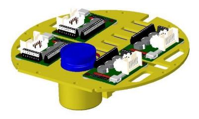
A second new development concerns the chassis, the middle floor of the robot, which houses all the electronic components. This year, the part was completely redesigned and the capacitor that feeds the electronic circuitry was repositioned to better balance the robot's center of gravity. The area that houses all the electronic components was redesigned. This has improved the robot's center of gravity, making it more balanced and eliminating the problem of wobbling during forward acceleration. The 3D model of the assembled electronics holder with the electronic components is shown in Figure 8.
References
- IR213 Driver datasheet page, https://www.infineon.com/dgdl/Infineon-IR213-DS-v01_00 EN.pdf?fileId=5546d462533600a4015355c8a02116a5
- Kolano, K., Drzymała, B., Gęca, J.: Sinusoidal Control of a Brushless DC Motor with Misalignment of Hall Sensors. Energies. 14, 3845 (2021).
- HWu, H., Wen, M., Wong, C.: Speed control of BLDC motors using hall effect sensors based on DSP. 2016 International Conference on System Science and Engineering (ICSSE). (2016).
- Pindoriya, Rajesh M., Saravanakumar Rajendran and Priyesh J. Chauhan.: Speed Control of BLDC Motor using Sinusoidal PWM Technique. (2015).
- Shahrubudin, N., Lee, T.C., Ramlan, R.: An Overview on 3D Printing Technology: Technological, Materials, and Applications, Procedia Manufacturing. 35, 1286-1296 (2014).
- Abiyev, R., Gunsel, I., Akkaya, N., Aytac, E, Abizada, S., Say, G., Yirtici, T., Yılmaz, B., Bürge, G., Makarov, P.: Decision Making and Obstacle Avoidance for Soccer Robots. (2020)