OMID 2022 Team Description
Mohammad Hossein Zolfaghari Abir, Farhan Daemi Mojdehi, Kevin babakhanluo, Hashem Khan mohammadi, Farhad Najafi, Omid Mahdizadeh, Vahid Akbari, Alireza Sahebi, Mohammad hossein Zahedi, Javad Rahmani
Department of Biomedical Engineering of Shahed University of Tehran, Iran; Department of Electrical Engineering of IKI University of Ghazvin, Iran; Department of Mechanic Engineering of Amirkabir University of Tehran, Iran; Department of Electrical Engineering of Shahed University of Tehran, Iran; Department of Electrical Engineering of Khaje Nasir University of Tehran, Iran; Department of Bioinformatics of Sharif University of Tehran, Iran; Department of Electrical Engineering of Tehran University of Tehran, Iran; Department of Electrical Engineering Islamic Azad University Science and Research Branch
Abstract This paper represents recent technical improvements of the OMID robotic team in Robocup 2022 Small Size League, Bangkok, Thailand. In this paper we are talking about changes in mechanics, the new mechanic in 2020 wasn't good enough and now we design some new parts, in the electronic we implemented gyroscope sensors to improve robot control and tools to debug FPGA VHDL code and the final part, software and strategy are about new algorithms in ER-Force simulator and changes in our communication protocols between robots and our main server.
1. Introduction
Omid Robotics Team(ORT) began as a small size team in 2007. ORT has participated in competitions since 2007 as a branch of the robotics society of the Department of Electrical Engineering of Shahed University, Tehran, Islamic Republic of Iran. This paper focuses on three general topics: mechanics, electronics, and software. The second section following the introduction discusses our new mechanical platform and some changes improving robot's movement. By using gyro sensors, the robots have the ability to correct their movements in real-time, which is discussed in section three. Also, new algorithms and strategies are explained in section four.
2. Mechanical system
In this section, we will explain improvements to our design of the Omid team's smallsize robots and the problems of the previous version. The design has changed entirely in the motor and wheel configuration. In sections 2.1-2.5, more explanations are accessible.
2.1 Motor improvement and configuration
In the previous version, we improved the motors with brushless 50watt motors and installed the motor at a greater height than the wheels[3]. Before corona, we had made a primary model to test these changes. The results were worse than expected; at high speed, robots play very badly and often rollover at high speeds.
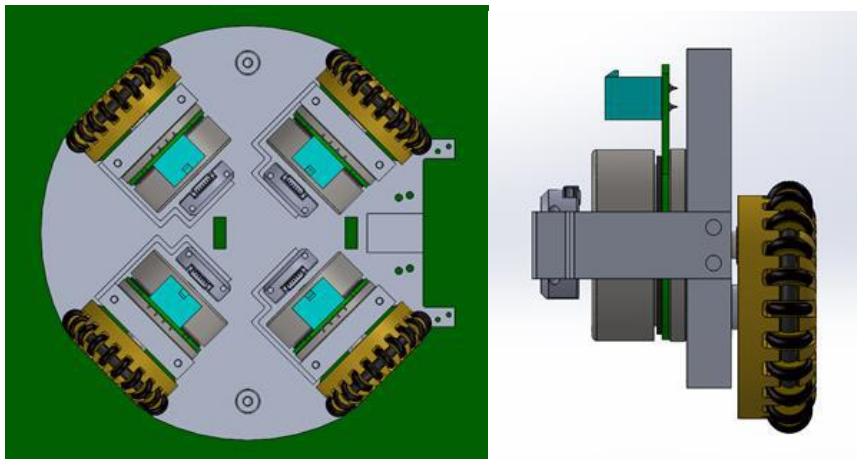
So we decided to change the motor height back to the former motor configuration. The wheels have a 90-degree difference compared to each other, and motors are installed at the lowest level possible achieve the minimum center of mass.
2.2 Wheel layout configuration
In order to decrease the height of the motors, we change the back gear to an interior one, keeping the number of sub-wheels (22 sub-wheels) and diameter (50mm)[3].
2.3 Capacitor and battery layout design
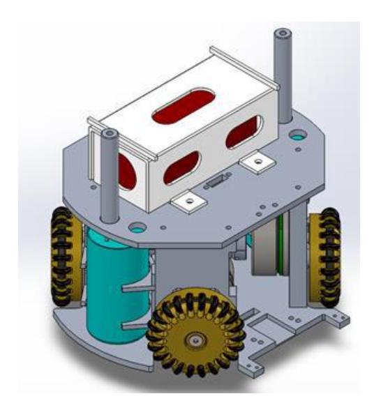
The capacitor was placed vertically near the motors to prevent the COM1 height from rising like the previous version. Still, there isn't any place for a battery behind the robot, so we put the battery in the second layer near the shooting board.
2.4 Spinback
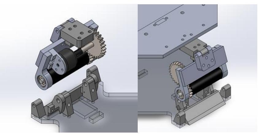
In this version, we designed a simple and small spin back system. We have a roller and a system to set up the distance between roller, ball, and ground. The design details are visible in figure3.
2.5 Conclusion
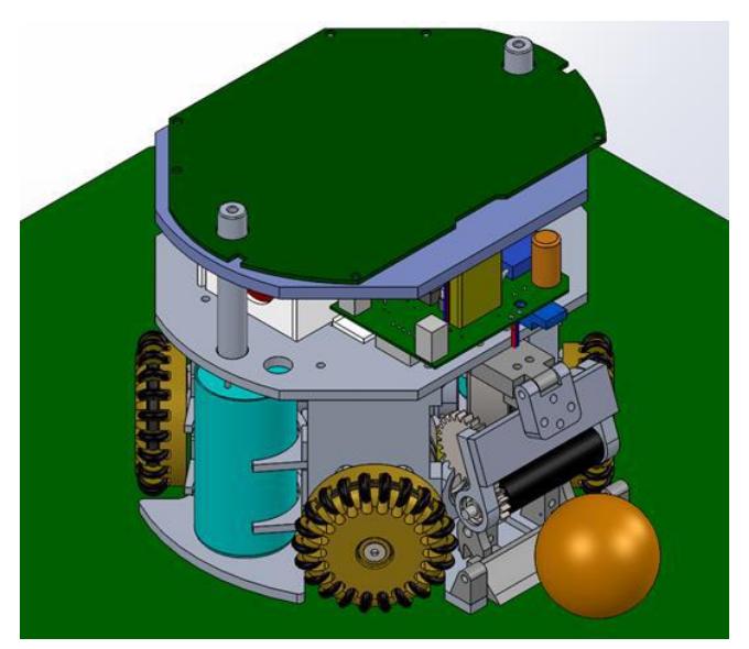
After assembling the parts in SolidWorks, the final robot body was achieved. It is presented in figure 4. We are still working on the mechanic, and the next step is designing the damper system.
3. Electrical System
This section explains two subjects: implemented gyroscope sensors to improve robot control and tools to debug FPGA VHDL code.
3.1 FPGA Debugging
We used the ISE software Chip scope and simulated it in FPGA to simulate and accurately see the motor signals coming into the MOSFETs. We improved engine performance [1]. In the robot shoot section, the code and the pulse width and pulse bandwidth modifications were made dramatically. We optimized the switching frequency in various ways to have the most firepower and maximum power available.
3.2 Adding Gyro
Due to vision delay and Extra rotations of the robot, we decided to use a separate vision system to complete rotation information. Compass did not meet our needs because of the high noise generated by the shoot, so we used the GY 9250 Model. According to tests, this model is more precise and faster than other models, as well as nine axials, and gives us linear acceleration so that we can further modify the robot's motion using linear acceleration [2]. It has a lower price tag than other models.
3.3 Calculating Angle
With the integral, we get the angle of acceleration. Still, due to the accumulation of errors, the purpose of this is to reduce the amount of error by using the camera frame. t defines the time interval between each gyro data, and 200 is the vision framerate.
- $n = \frac{200}{t}$
- $\theta_{AI}^{\cdot} = \frac{\theta_{AI}(new) - \theta_{AI}(old)}{t}$
- $\dot{\theta}{t} = \sum{0}^{n} \ddot{\theta}{t} + \dot{\theta}{AI}^{\cdot}$
Placement (2) in (3) calculates the Angular acceleration array.
θi define gyro data in between 1-n and With the addition data new data Alternatives old data.
$$\theta = \sum_{i=0}^{n} \dot{\theta}{i} * t + \theta{AI}$$
θ defines the real angle of the robot and calculates it in (4)
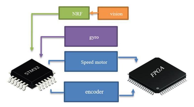
NRF sends the robot's angle to the Arm. Arm calculates data then returns the speed value to FPGA [3]. For decrees error we used a low filter for gyro data; if the data has a low value, we will consider zero.
4. Software
(Covered by subsections below)
4.1 Alterations
As the Robocup 2021 competition was decided to be held virtually and the regulations of the Robocup Small Size League was changed, holding matches in the ER-Force simulator, we have changed almost all of our communication protocols between the robots and our main server. One of the main alterations that we made to our robots' communication was adjusting the data size which we send to each robot. To be more specific, we now send the robot a linear 2-dimensional velocity vector as a moving command instead of sending four separate motor speeds. Then the robots will calculate the required speeds for each motor using their ARM and FPGA processors and give it to each motor using a PID feedback control system. We are using linear speeds because we can control robots better this way because when we reduce the size of sending data, the processing speed and sending bit rate will be increased. Before we made this change, we had been losing a significant amount of data that we were about to receive from the vision server. This data loss was due to the time of sending data to robots, making a very big timeout or delay in the whole processing system. Another change that we made in our data sending process is that we now send the robot's angle from the vision server to the robots. This will give the robots the ability to correct themselves if it is at the wrong angle.
4.2 Strategy
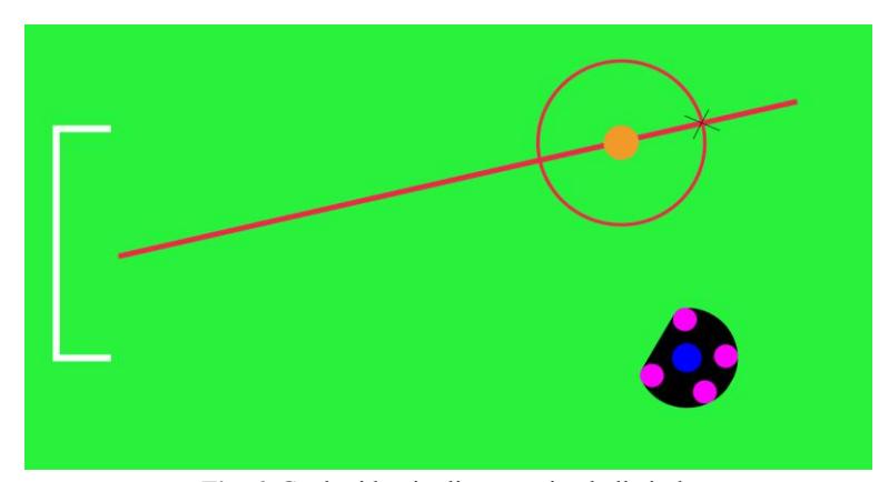
The strategy of playing a game in small size soccer robots is to score a goal without making a foul. In order to do this, we need to pay attention to all playing modes received from the Referee. These commands will let us know the current state of the game. Our base C++ code contains the main thread, which is supposed to do all the AI processing and calculations. In this thread, we check all the specific commands that the referee gives us and make the best robot decision. First of all, to score a goal, we need the closest robot to the ball to go behind the ball. After we find the nearest robot to the ball, we need to calculate the exact position that the robot should be in. So we have some geometry calculations. We calculate the coordinates of the cross point of a line crossing a circle around the robot. More details are shown in figure 6.
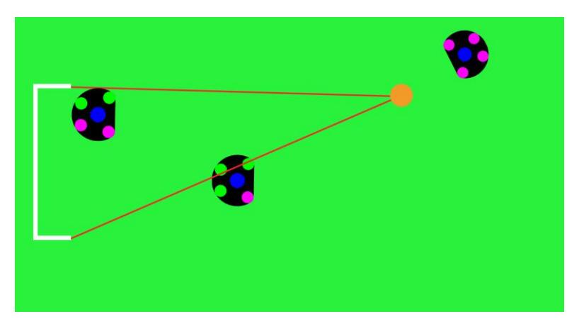
After we find the exact position that the robot can score a goal from, the robot will go to this position using the robot navigation algorithm. Then we need to consider if the goal is wide open or if there are obstacles in the ball path to the goal. To do this we can draw a cone from the ball to goals top and bottom points. Then we will check all the opponent robots if they are inside this cone or not. Next we find the biggest angle between all the robots inside this cone and of course this angle must be greater than ball diameter, so that the ball can pass easily through it. There is an exception when the opponent robots are covering the whole area or there might be a possibility that they will cover the whole goal area in future. In this case we cannot score a goal or in other words the possibility of scoring a goal will be decreased. So we need to call another algorithm to pass the ball to another robot which has a better position to score a goal.
To pass the ball into a specific direction that the other robot is able to receive, we have an algorithm that first of all defines the sender and receiver. The sender robot is the one that is closer to the ball than the others. The receiver robot is the one that has a better position to score a goal than the others. After choosing the sender and receiver for a pass we need to define a position that the receiver robot should be in. In order to do this we draw two lines from sender to receiver that will cover the whole area between them that might be covered by an opponent or a teammate robot. If it is covered, we need to change the receiver's position. It's better to choose a position that is closer to the opponent's goal and also is more clear of other robots. Whenever the receiver arrives in the right position, the sender can make the pass and shoot the ball through the receiver. So the main strategy will be continued as mentioned.
4.3 Ball Placement
Ball placement used to be done by a human referee in previous competitions. Since Robocup 2021 the robots must have the ability to place the ball in the position given by the referee as a BALL_PLACEMENT command. To do this we added one more play mode in our cases as a ball placement mode. In this mode the robot will move behind the ball and turn on it's spinback. Then it will approche to the ball slowly until it gets the ball inside the kicker. Now it can move to the position given by the referee and releases the ball there and at the end it returns back to its formation.
References
- Xilinx: Spartan-6 FPGA Family datasheet
- Specification: MPU 9250 datasheet
- Omid Robotics Team.: OMID 2019 Team Description paper. Technical report, ECE Department, Shahed University of Tehran, 2020.
- LE, Chap T.; EBERLY, Lynn E. Introductory biostatistics. John Wiley & Sons, 2016