RoboCup 2022 TEAM DESCRIPTION PAPER Ri-one SSL
Takumu Hirohashi, Ryusei Hotta, Tasaka Takayuki, Yudai Matsumoto, Daiki Tomioka, Yuzuru Naito, Kazuki Wakao, Tomoyasu Takagi, Shu Murase, Koshi Wakabayashi
Ritsumeikan Univercity
Abstract This paper will be used to qualify for the RoboCup2022 Soccer Small League Tournament. Our team's robots and systems are designed according to the rules of RoboCup 2020. Our research activities are based on classifying activities into hardware, software and circuits and repeating various operational tests. This paper describes software in terms of its overall structure and obstacle avoidance algorithms. We are also working to enhance communication and debugging by creating a GUI. The hardware describes innovative technology with dribblers and wheel units. In the circuit, we challenged to develop a new motor driver and designed the circuit to stabilize the power supply.
1 Introduction
We are a student group aiming to be the best RoboCup team in the world, recognized as a project group of the Faculty of Information Science and Engineering, Ritsumeikan University. He has won top prizes in world competitions such as 2DSoccerSimulation, RescueSimulation and @Home League. The SSL team was formed last year, and recently participated in the Robocup Asia Pacific tournament, finishing 5th in the first appearance. If the right to participate in this tournament is recognized, we aim to win the world championship. This paper is a continuation of the description paper for the Asia Pacific Convention and introduces new development efforts compared to the previous one.
2 Electronic Design
2.1 Moter Driver
When we looked into the major drive methods for BLDC motor drive, we found square wave control and sine wave control. However, when we learned that there was a control method called FOC (Field Oriented Control) that could provide better performance than sine wave control, we introduced it to our motor driver[1]. The torque of a motor is generated by the action of the force of attraction and repulsion of the magnetic flux generated by the permanent magnet and coil. Since the magnetic flux of the coils is determined by the current, the three coils need to be controlled according to the angle of the motor in order to be efficient. Our motor driver uses an inverter to convert the current of the three phases into a current in the direction of the magnetic force that creates the torque; the FOC is a system where the torque created by synthesizing that torque rotates the coils. We make this system work by receiving feedback from the angle of the coil and the current flowing through the coil.
2.2 Main Board
The main board contains the Raspberry Pi4 to communicate with the AI PC and motor drivers. STM32F446RET6 is installed for each of the four motor drivers. Previous motor drivers used the DSPIC33EP512MC806PIC microcontroller, which has a maximum clock frequency of 60Mhz, but decided to use the STM32F446RET6, which has a faster maximum clock frequency of 180Mhz. The RaspberryPi4 and the individual STM32F446RET6 are communicating with each other via CAN(Controller Area Network). The reason for using CAN communication is that it allows for multiple communications on a single line and is expected to reduce noise. By consolidating all the modules on a single main board, the communication is stabilized by reducing the number of communication lines, and the maintainability in case of robot failure is considered.
2.3 Protection Circuit
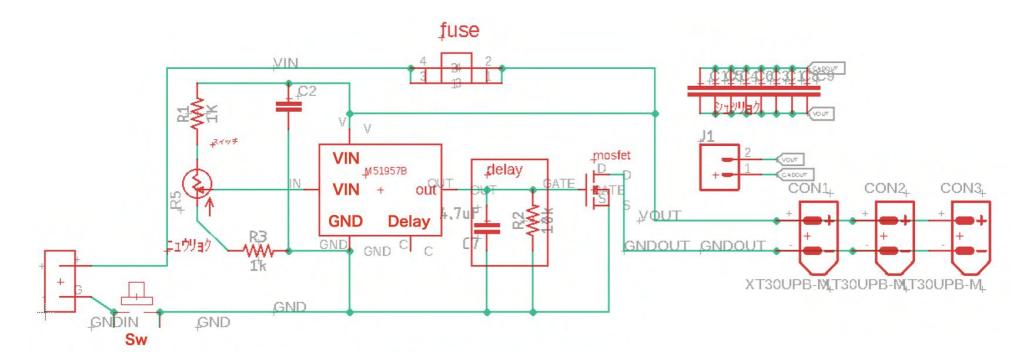
Our robot uses a lithium-ion battery. This battery has a very high output and is indispensable for our robots. However, unlike ordinary batteries, it should not be discharged to 0V. Over-discharging leads to deterioration of the battery electrolyte. Batteries also store overcurrent and high energy. This battery can burn if not handled properly.
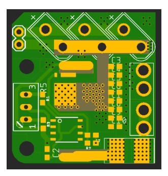
We are using an IC(Integrated Circuit) called M41957B. If the voltage of the 3-cell lithium-ion battery drops below 9V, power is cut off by the MOSFET.
3 Mechanical Design
3.1 Wheel Units
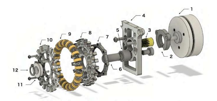
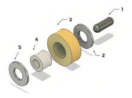
Figure 3.1 is an exploded view of the wheel unit on the Ver4.0 robot. The parts are roughly composed of 12 parts. EC-flat (30W) is used as the motor. The torque is obtained by adding a reduction gear to the 30W type, which is cheaper than high-power motors. The gears in item 7 were made by ourselves using a wire-cut electric discharge machine. This component makes it possible to save space and achieve a lower center of gravity than before. Twenty subwheels are installed. The structure of the subwheel is shown in Figure 3.2. It consists of five parts and is simple and inexpensive to manufacture. The wheels are fastened with E-rings. The E-Ring keeps the wheel in place and reduces the risk of failure.[4]
3.2 Dribblers
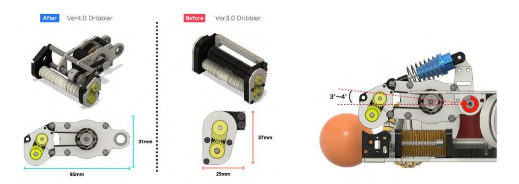
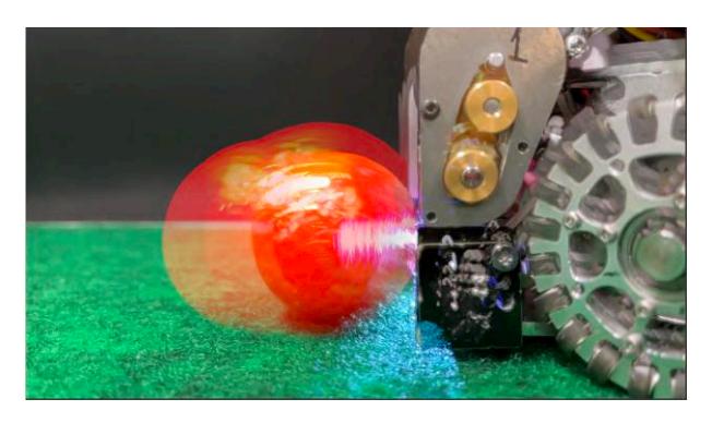
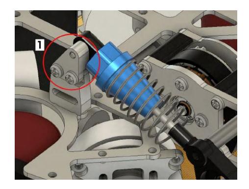
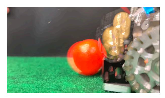
Figure 3.3 shows a comparison of Ver4.0 and Ver3.0 dribblers. The dribblers we have developed so far are completely fixed like Ver3.0, making it difficult to pass the fast ball around. This is because fast balls, when they hit the tube part of the dribbler, play as they are, and it is very difficult to hold them well. As shown in Figure 3.5, the Ver3.0 dribbler has difficulty in holding a fast ball. So we decided to solve this problem by making the dribbler movable instead of completely fixed, as shown in Figure 3.4, so that it moves 3 to 4° around its axis when it captures the ball, and uses an oil damper to suppress the vibration of the ball. The spring and oil used for the oil damper can be changed. It is also possible to change the position of the damper by replacing the fixed parts in Figure 3.6. This dribbler has the strength to be fine-tuned in all situations. Figure 3.7 was optimized at the current stage (2022 March) by modifying the springs and fixed parts, and shows that vibration is reduced compared to Figure 3.5. However, this is still a prototype experimental stage, and we believe that we can make a more accurate dribbler. We would like to conduct more experiments in the future to find the optimum solution[3].
3.3 Kicker
3.3.1 Mechanism
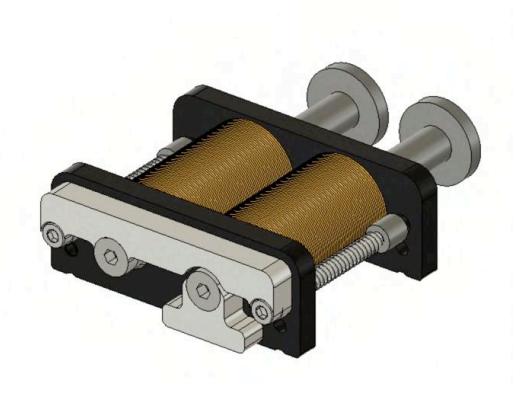
Figure 3.8 is a ver4.0 robot kicker. It is equipped with both straight kick and chip kick.
In the ver3.0 robot, only straight kicks were available, but we added chip kicks for defensive robots and goalkeepers because of the importance of clearing with chip kicks.
Instead of placing two solenoids vertically, we placed them horizontally as in Figure 3.9 to create more space for the dribbler.[4]
3.3.2 Circuit
The kicker circuit has a function to adjust the power of the kick. This function is made possible by PWM(Pulse Width Modulation) control using MOSFET and gate drivers to adjust the power. To increase the power of the kicker, the voltage applied to the solenoid is increased to 200V by a voltage boost circuit. In addition, that voltage is stored in two 2200mµ in parallel to produce more power. The timing of the kick is controlled by the infrared sensor, which is a ball-holding sensor that enables the ball to be kicked in close contact.

4 Software
4.1 Software Design
We at Ri-one SSL have been developing using ROS2 foxy for some time now. However, the documentation was difficult to understand and the system was still incomplete, we could not implement it optimally and it became a bottleneck. The decision was made to build an AI running on a server PC from scratch using Python, which is easy to understand. It is ideal for a student organization with a high turnover of staff. As a result, the use of the ROS's original communication standard was stopped, and by using only Google Protocolbuffer, the difference between grSim and the actual device was reduced and the efficiency of development was improved.
We stopped using DDS (Data Distribution Service), the accuracy of communication is considered to have decreased, however, due to the frequency of command transmission is high, there is no effect on the robot operation. In order to use the speed in the local coordinate system, we use Raspberry Pi to receive the Protobufs to secure the calculation processing performance of the rotation speed of each wheel. Therefore, mbed is placed between the hardware and the Raspberry Pi because it is more suitable for GPIO (General-Purpose Input/Output) controlling.
In terms of processing speed, Python is inferior to compiler languages. There is also the problem of requiring a certain amount of resources to execute. As a workaround, we implemented the robot software in the Go language.
4.2 Network/Communication
4.2.1 Communication Method
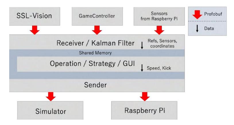
The RACOON-AI, our strategy software, receives the data sent by the Vision server and Game Controller via multicast. At the same time, it receives the sensor information of each robot via UDP as well. Golang is used for receiving to increase the performance. The received data is processed by Kalman filter and passed to the strategy system. A synchronous communication method is used, where all Vision data is received and processed after each frame. The details of the communication flow are as shown in the Figure 4.1.
4.2.2 Maintaining Compatibility With the Simulator
In the competition at RCAP2021, the problem of the differences between the simulator and the actual robot was remarkable, and there was a situation where the actual robot did not operate as expected. In order to avoid differences in the operating environment of the simulator and the actual robot, we adjusted the data sent from RACOON-AI, so that there were no differences between grSim and the actual robot. By doing so, the RACOON-AI that was running in the simulator can be seamlessly transferred to the real robot environment without changing the code.
4.2.3 Router Load Problem
We have been using Wi-Fi access points and routers that are sold for home use. The data sent to and received from the robot is constantly being routed through many packets using UDP, which is a heavy load. Since this type of usage is not expected, the solution is to use a higher-grade router and access point. This time, we used Yamaha RTX1220 and Cisco Aironet 3702E as the new router and access point. These access points can communicate with up to 200 units.
4.3 Obstacle Avoidance
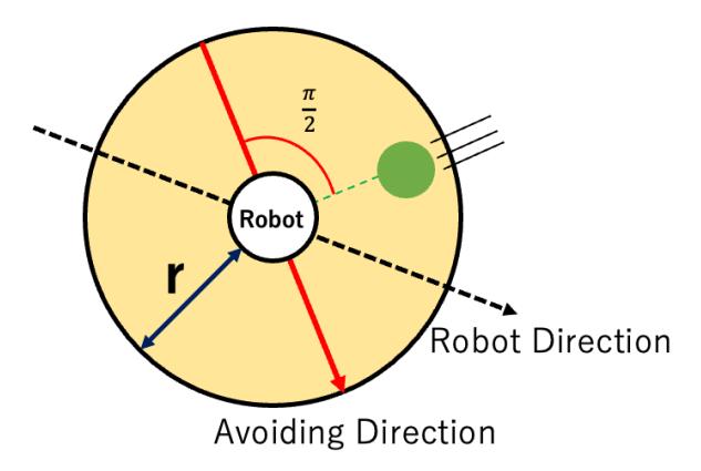
It is essential for each robot to avoid obstacles as it moves. The distance between each robot is calculated, and if there is a possibility of collision, it is avoided. The obstacle avoidance algorithm currently implemented is shown in the figure below(Figure 4.2). First, inspect all our robots. The distance r increases with speed, and when the velocity is zero, the distance r is also zero. Second, increase speed when an obstacle is approaching. The avoid direction is π/2 from the angle of invasion. Finally, select an avoiding direction as close to the robot direction as possible.
4.3.1 Obstacle Avoidance Algorithms To Be Introduced
Currently, the above obstacle avoidance algorithm is implemented, but in the future, we are considering changing to the algorithm shown below for smoother obstacle avoidance. The flow of the algorithm consists of the following two main processes.[2]
- Resulting Search Space
- Maximizing the Objective Function
![Figure 4.3: [2]](/tdps/soccer_smallsize__2022__Ri-one/_page_8_Picture_8.jpeg)
4.3.2 Resulting Search Space
- (a) $V^s$ : Determine the maximum and minimum range of control inputs that the robot can take. This value uses the maximum speed, etc., which is determined by the specifications of the motors installed in the robot.
- (b) $V^r$ : Determine the current speed and the maximum and minimum range that can be taken until the next time calculated based on the maximum acceleration/deceleration.
- (c) $V^a$ : Determine the range of control inputs that allow the robot to travel safely, calculated from the observations made by vision and the maximum deceleration value of the robot.
By considering only the range of control inputs that overlap these three ranges, we can use only those control inputs that are safe and consider the robot's kinematic model.
4.3.3 Maximizing the Objective Function
Also, the following evaluation functions are calculated for each sampling control value.
$$G(v,\omega) = (\alpha * heading(v,\omega) + \beta * distanceobject(v,\omega) + \gamma * velocity(v,\omega))$$
- (a) Target heading : $heading(v, \omega)$ is the value obtained by subtracting the angle of the difference between the direction of the robot and the direction of the goal from 180 degrees. If you are heading straight to the goal, the evaluation value will be higher.
- (b) Clearance : $distanceobject(v, \omega)$ indicates the distance to the obstacle closest to the robot. The farther away from the obstacle, the larger the evaluation value.
- (c) Velocity : $velocity(v, \omega)$ is the value of the robot's velocity v. The faster the speed, the larger the evaluation value.
$\alpha$, $\beta$, and $\gamma$ are weight parameters for the linear addition of each term. By adjusting these parameters well, control inputs that can run at high speed while heading toward the goal and avoiding obstacles will be calculated sequentially.
By introducing this new obstacle avoidance algorithm to our robots, we will be able to perform obstacle avoidance more smoothly and approach the victory of the team[5].
4.4 Positioning
4.4.1 Placement Of the Offense
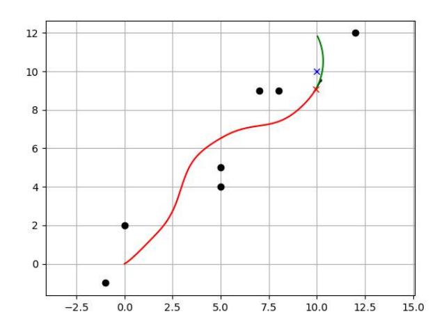
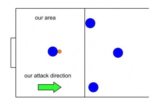
Currently, we have four robots assigned to the role of offense. One of the robots is given the role of attacker, and the other robots are assigned the role of receiver of the pass. In this section, we describe the algorithm for the placement of the robots(Figure 4.5).
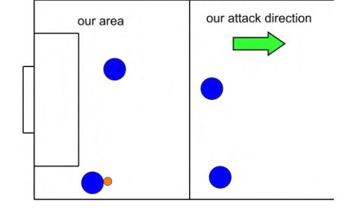
When the ball is inside the goal area, place one robot on each side of the attacker and one robot in front of the goal(Figure 4.6).
When the ball is outside the goal area, we place one unit parallel to the y-axis, one unit positive to the x-axis, and one unit diagonally in front of the attacker.
We also have an algorithm to balance the positions of all the robots, since we have a limited number of robots in defense(Figure 4.7).
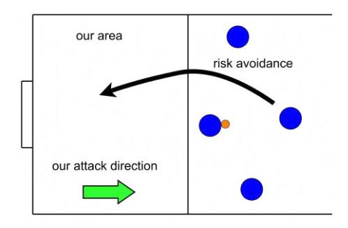
When three robots, including the attacker, are attacking at the opponent's position, one robot is equipped with an algorithm to manage the risk and return to its own position.
4.4.2 Placement Of the Defense
When three robots, including the attacker, are attacking at the opponent's position, one robot is equipped with an algorithm to manage the risk and return to its own position(Figure 4.8).
4.5 Keeper
First of all, consider a semicircle whose center is the goal coordinate and whose radius is the sum of the radius of the goal and the radius of the robot. This semicircle will be the basic trajectory of the keeper. Next, connect the coordinates of the ball and the goal with a straight line. Find the intersection point of this line and the semicircle and guide the keeper to that coordinate. By doing this continuously every 16ms, it is possible to play the ball naturally.
In addition, by adding the component of the ball's velocity in the direction of the robot's movement vector to the robot, it is possible to move to the designated position more quickly.
4.6 Pass Processing
4.6.1 Attacker
The first step is to check the situation of the attacker and determine the robots that can pass. Then it selects the robot that is likely to score a goal, and pass the ball to it.
4.6.2 Receiver
The robot to be passed will stop once. This is to ensure that the robot receives the ball. The next step is to calculate the trajectory of the ball, determine its normal, and find a straight line passing through the robot's coordinates that is horizontal to the normal.The intersection of these two lines is set as the target coordinate, and the receiving robot is made to go there. At this point, if the receiving robot is capable of shooting, turn the robot toward the goal and specify the target coordinates so that the intersection point is right in front of the robot.
4.7 GUI
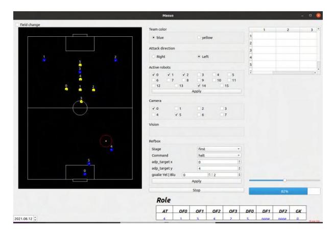
We are currently working on a GUI using QT. As of now, our GUI is capable of displaying the positional information of each of the friendly and enemy robots and the ball in the field, as well as superficial court changes on the GUI. This enables us to check the robot's behavior during a match and to notice any abnormalities.
We are also planning to implement the following new features in our GUI.
- Display of the individual status of each robot (e.g. battery voltage on the actual machine)
- Display velocity vectors for robot and ball
- Ability to change the definition values used for robot control without the need for an editor
We believe that these additions will make a significant contribution to debugging and eliminate the differences between grSim and actual soccer, making the game run more smoothly.
5 Conclusion
In this paper, we have presented new technologies and strategies in software, hardware and circuits from Robocup Asia Pacific 2021 to the present. In the future, we would like to use artificial intelligence techniques to give our software the ability to learn, and in hardware, we would like to work hard to improve the kicking accuracy of chip kicks and the ball retention ability of dribblers, which are new endeavors.
6 Acknowledgements
I would like to thank the people at Ritsumeikan University, especially AIOL, for their research guidance in the preparation of this paper.
References
[1] SimpleFOC Driver and Support Library. https://github.com/simplefoc/Arduino-FOC-drivers [2] Fox, D., Burgard, W., Thrun, S.: The dynamic window approach to collision avoidance. IEEE Robotics & Automation Magazine 4(1), 23–33 (1997) [3] Huang, Z., Zhang, H., Guo, D., Jia, S., Fang, X., Chen, Z., Wang, Y., Hu, P., Wen, L., Chen, L., Li, Z., Xiong, R.: Zjunlict extended team description paper for robocup 2020 (2020) [4] Ryll, A., Jut, S.: Tigers mannheim (team interacting and game evolving robots) extended team description for robocup 2020 (2020) [5] Thrun, S., Burgard, W., Fox, D.: Probabilistic Robotics. Minabi Shuppan (2015)