RoboJackets 2022 Team Description Paper
B. Perez, D. Lam, S. Challa, K. Fu, H. Gynai, A. Sohrab, C. Clark, A. Srinivasan, A. Gordon
Georgia Institute of Technology
Abstract This paper describes the improvements implemented by the Georgia Institute of Technology's RoboCup SSL team, the RoboJackets, in preparation to compete in RoboCup 2022 in Bangkok, Thailand. This year's changes to our mechanical and electrical systems primarily focused on improving stability, consistency, and accessibility. Changes to our software stack focused on improving communication between robots as well as implementing a new behavioral assignment system.
1 Mechanical
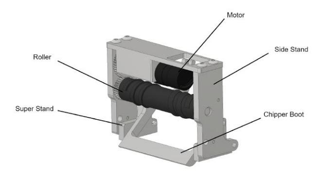
Changes to the 2022 design were primarily focused on improving accessibility, iterability, and consistency. Subassembly mounting was consolidated to the bottom baseplate of the robot (as opposed to the midplate) in order to simplify troubleshooting and repair of motors and solenoids. The shell was simplified to a single uninterrupted part, reducing the risk of wires or boards being caught and damaged.
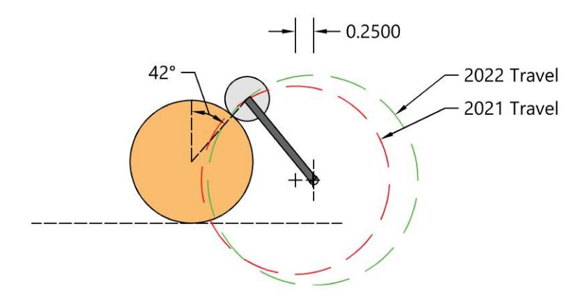
The dribbler mechanism underwent multiple changes this year to improve the fleet's ball retention and control abilities. An in-house molding process was utilized to develop a helical design for the roller, which allows it to center the ball during operation. Dribbler geometry was also modified to change the ball contact point and pivot behavior of the assembly while providing other small benefits detailed in Section 1.1.
Below is a table summarizing this year's changes to the 2022 robot fleet.
Table 1. Robot mechanical changes from 2021 to 2022
| Part | Changes |
|---|---|
| Dribbler roller | Size increased by 9mm, new geometry, new 3D printed mold |
| making process | |
| Dribbler pivot point | Mounting position moved backwards 6 mm |
| Chassis | Mid- and baseplates made independent of motor stands |
| Shell | Replaced multiple pieces with a single piece shell |
| Solenoids | Combined into a single unit mounted to the baseplate |
| Motors | Chipper motor moved to the baseplate |
| Chipper and kicker shafts |
New pin and narrower mounting tolerances |
1.1 Dribbler
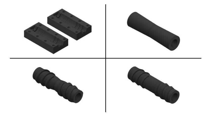
With the help of team TIGERs Mannheim, a set of 3D printed molds were developed to test multiple new roller designs [1]. These mold negatives are printed using PLA at a layer height of 0.1, then fastened together and filled with a two-part polyurethane to create the dribbler. This process can be done entirely in-house, eliminating lead times and costs associated with outsourcing parts. With the use of 3D printing, roller geometry can easily be modified and a mold negative can be quickly printed, allowing for the rapid iteration of new designs.
Using this method, multiple prototype designs were created and their ability to center the ball was compared. A control shape with identical geometry to the 2021 roller was also tested to evaluate the effectiveness of the molding process. The in-house prototypes performed similarly to ones manufactured through outsourcing, with minor differences. Centering on the in-house made roller was consistently more effective from one side, even though the designs were symmetrical. This roller also produced slightly more vibration while spinning the ball. Despite these differences, in-house prototyping proved to be an effective strategy, and a final roller design with helical geometry to effectively center the ball (pictured in the bottom left of figure 1) was selected for use on this year's fleet.
1.2 Chassis
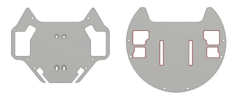
Mounting of both the solenoids and motors have been consolidated to the baseplate of the robot (as opposed to the midplate) in order to simplify troubleshooting and repair. To accomplish this, the midplate now attaches directly to the baseplate with standoffs. Both solenoids are now also contained in a single holder. Previously, the chipper solenoid mount and motors were mounted to the midplate, hindering disassembly. These new changes enable the bottom half of the robot to be quickly removed for easy access. Dedicated wiring channels (indicated below in red in figure 4) have also been created for the solenoid, motor, and encoder wires to prevent these wires from catching on interior parts and allow for greater ease of assembly.
1.3 Shell
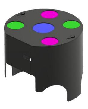
The previous shell design consisted of 3D printed halves attached by magnets. While easy to use when not attached to the robot interior, its real-world performance was poor due to wires frequently being caught on the interior of the shell. Protrusions necessary to hold the magnets and prevent shearing became catch points for wires, which often resulted in damaged boards and difficulty accessing the interior of robots.
The new shell addresses these issues by removing all extraneous interior geometry. It consists of a single 3D printed piece that mounts to standoffs on the midplate rather than directly to the baseplate. The use of thumbscrews allows it to be removed without any additional tools, making it easy to gain access to the interior of our robots when necessary.
2 Electrical
This year's modifications to the electrical system focused on improving stability and reducing the negative impact of human error on the robots. This includes replacing the control board batteries with higher capacity ones, changing the kicker and breakbeam board designs, and implementing an automatic Robot Shell ID system. The table below summarizes this year's changes to the electrical system.
Table 2. Robot fleet electrical changes from 2021 to 2022
| Part | Changes |
|---|---|
| Control Board | Higher capacity batteries, appropriate connectors added |
| Kicker Board | Standardized connectors and changed potentiometer location |
| Breakbeam | Designed multiple boards for varying functions, added status |
| indicator LED | |
| Shell ID | Replaced rotary dial with automated ID system |
2.1 Control Board
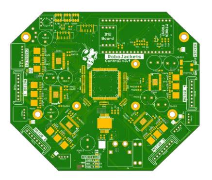
New, higher capacity batteries are being utilized on the fleet this year to increase the amount of time each robot can run before being charged and reduce the number of times batteries must be swapped in the fleet over the course of a match. These batteries' smaller size also increased the space available for other parts that perform vital functions. Because batteries utilize XT60 plugs for power delivery, the control board's DF22 was replaced with an appropriate new connector. The control board was also improved by the addition of higher retention connections for the robot's flat flex cables in more optimized positions as well as a more appropriate connector for power delivery between the control and kicker boards. Finally, unnecessary parts were removed from the control board, including a dip switch previously used for troubleshooting and power reset circuitry, in order to make room for more useful functionality.
2.2 Kicker Board
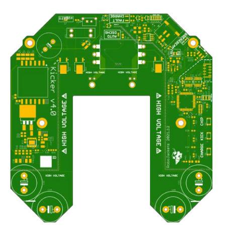
As with the control board, revisions to the kicker board were largely focused on altering the existing circuitry and the addition of new connectors. The connectors for power delivery and to interface with the breakbeams are now standardized using Molex's Micro-Fit family of connectors. These connectors are used in multiple places on the robot to allow for greater ease of repair and to reduce the number of unique parts that must be ordered for fleet construction and maintenance. Additionally, the potentiometer used to tune the breakbeam's sensitivity is now in a more accessible location for easier use while the robot is fully assembled.
2.3 Breakbeam
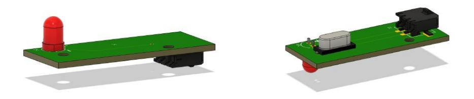
The previous breakbeam design utilized the same board for both receiving and transmitting the breakbeam, while this year's design split the two functions into separate boards. While a single footprint made design easier, the doublesided board was confusing to assemble and as a result was frequently assembled incorrectly.
2.4 Robot Shell ID
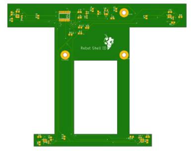
This year, a new form of robot identification was implemented using Robot Shell ID. Previously, robot identification was done through a manual rotary dial that communicated with the field computer. The robot ID would be set via this dial prior to the match. In order to increase the process' efficiency and prevent potential human error, this process was automated using TSL2572 light-to-digital converters. This sensor contains an analog-to-digital converter which sends digital output based on the the lux calculation by the visible light photo diode [2]. The new board contains four of these sensors as well as four white LEDs. These are located on the four corners of the board, as can be seen below in figure 9. These LEDs shine upwards and light reflects off of the bottom of the colored paper inside a robot's shell. Based on the intensity of a given wavelength of light measured by the sensor, the color of the paper above each sensor can be determined [3].
![Fig. 10. The color patterns associated with each robot ID [4]](/tdps/soccer_smallsize__2022__RoboJackets/_page_8_Figure_2.jpeg)
3 Software
RoboJackets has been a member of the RoboCup Small Size League for nearly 10 years. As a result, the team code base has a large amount of legacy code, with some areas being used frequently (e.g. motion control) and others no longer in use. The focus this year was on improving the integration of this existing code base with a more recently developed behavioral system, creating modular plays for this system, as well as simplifying the robot role assignment within this system to allow for more effective future development.
3.1 ROS Action Server
Last year, much of the codebase was switched over to ROS2, the Robot Operating System. This was done to allow the software stack to communicate more effectively between its C++ and Python components and to improve the organization of the existing C++ code. As an added benefit, ROS is an industry-standard organizational tool which allows our members (who are mostly undergraduates) to gain real-world experience in the field of robotics.
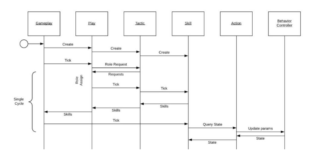
When switching to ROS, the C++ side of the codebase was entirely rewritten to fit the ROS framework of asynchronous nodes and topics. However, the behavioral gameplay code, written in Python, is made up of a series of static modules. The integration of these two systems exposed issues with this architectural split. Most notably, the Python stack was able to send requests to motion planning, but the motion planning stack was unable to return relevant feedback, such as the robot's position along its planned path. To remedy this, multiple ROS Action Servers were created. These allow clients (robots) to track the progress of requests, receive a final outcome, and cancel in progress requests when necessary, such as in the example move action server and client in figure 11 below [5].

3.2 Implementing Proposed Plays
In the months prior to the 2021 competition, the software team began implementing many of the changes proposed at the time of the last TDP in earnest. Though modules existed for the previous role assignment system and basic skills like capture and kick, the remaining parts of the decision-making AI, plays and tactics, were unwritten. Thanks to a more modular framework for decision-making than previous iterations of gameplay code, these plays were able to be implemented quickly and even helped the team achieve 3rd place in Division B. However, this implementation phase led to the discovery of many issues with the previous behavioral system.
3.3 Changes to Play Implementation
The previous play system was both inefficient and restrictive. In this system, each play was made up of specific tasks (tactics), such as shooting on goal and passing, each with a fixed categorical high, medium, or low priority. These priorities were further restricted to essentially 2 categories due to the top priority being solely reserved for the goalie tactic. These restrictions made it extremely difficult to implement both complex robot behaviors and decision making within plays.
The determination of robots' roles within a play took place on every gameplay tick (60 times per second), resulting in robots frequently switching roles based on small changes in cost functions. This made it nearly impossible to effectively implement certain behaviors, like passing the ball between two robots, because they would often switch between passing and receiving roles multiple times within the span of the play. Because critical behaviors such as passing were so difficult to implement, role assignment was changed to an event-triggered, auction based system rather than a categorical priority based system.
3.4 Role Assignment Changes
This greedy auction based role assignment was implemented to increase the speed at which our robots are assigned behaviors during plays as well as make new plays easier to implement. The previous system used an implementation of the Hungarian algorithm on all behaviors at once, which takes at least n 3 time to run [6]. In the new system, the highest priority role available at every step is "auctioned off" to the available robots, resulting in the lowest cost robot filling the highest priority role at every step [7]. While not optimal for minimizing costs among the whole fleet, this system reduces the run time of priority calculations and is an effective change from the previous categorical priority system.
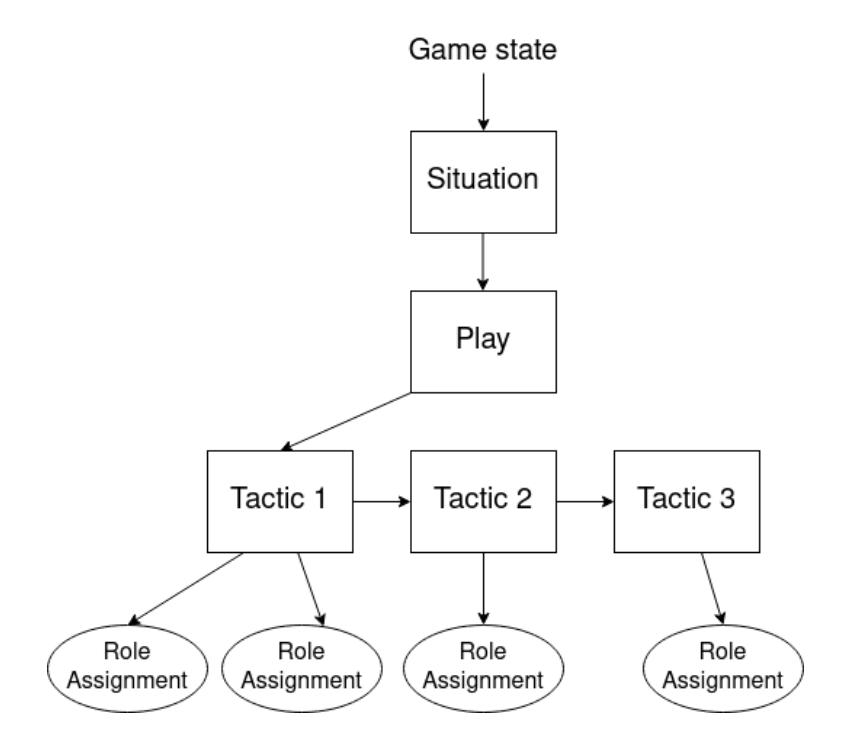
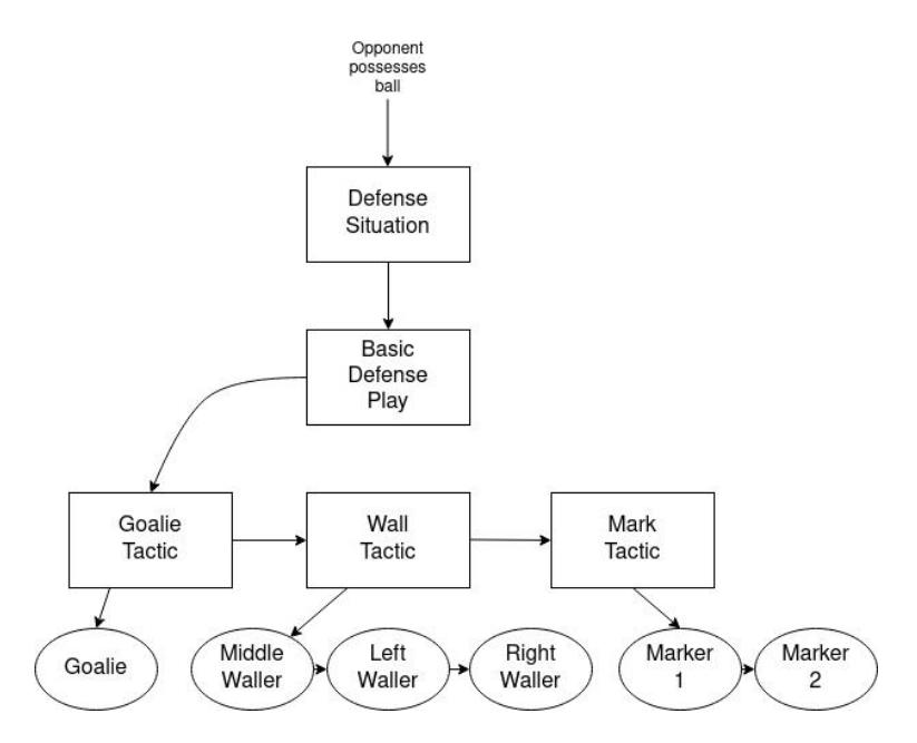
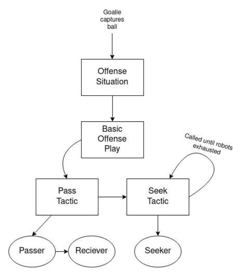
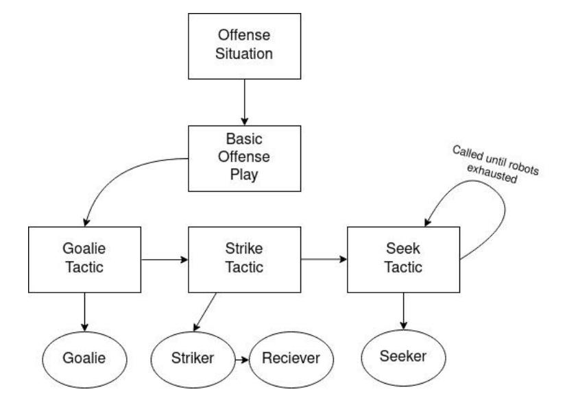
The new gameplay system is based off of a multi-agent behavior tree, with a "situation" based on the current world state as a root node. This parent calls appropriate composite nodes, "plays", which are responsible for managing robot behavior. These plays call child composite nodes, "tactics", which then auction off roles in descending priority order. Roles such as goalie, passer, or receiver, are assigned to robots based on cost functions within a tactic. After assignment, these roles give robots sequences of behaviors to execute in a given order until the tactic is complete or a change in situation results in the triggering of a new play. New tactics can continuously be called as needed, assigning roles to idle robots, until the gameplay situation sufficiently changes. An illustration of this basic framework can be seen in figure 13 below.
References
[1] A. Ryll and S. Jut. TIGERs Mannheim Extended Team Description for RoboCup 2020. 2020. [2] ams-OSRAM AG. TLS2572 Light-to-Digital Converter: Datasheet. url: https://ams.com/documents/20143/36005/TSL2572_DS000178_4-00.pdf/fb4f7438-f772-abd6-4405-79c5e3ca1315. [3] T. Bishop and G. Lee. TAOS Colorimetry Tutorial: The Science of Color. Tech. rep. 2006. url: https://ams.com/documents/20143/36005/LightSensors_AN000519_1-00.pdf/d2a0670d-7557-ed94-cc0e-225cfa8cb031. [4] Rules of the RoboCup Small Size League. url: https://robocup-ssl.github.io/ssl-rules/sslrules.html. [5] J. Perron G. Biggs and S. Loretz. Actions. url: https://design.ros2.org/articles/actions.html. [6] N. Tomizawa. "On some techniques useful for solution of transportation network problems". In: Networks 1.2 (1971), pp. 173–194. doi: https://doi.org/10.1002/net.3230010206. [7] L. Shamgah T. Tadewos and A. Karimoddini. "On-The-Fly Decentralized Tasking of Autonomous Vehicles". In: 2019 IEEE 58th Conference on Decision and Control (CDC). 2019, pp. 2770–2775. doi: 10.1109/CDC40024.2019.9029554.