RoboTeam Twente Extended Team Description Paper for RoboCup 2022
Corentin Monat, Elisa Dankers, Karina Skurule, Lotte Steenmeijer, Sander Sijtsma, Stelios Diamantopoulos, Rohit Aggarwal, Tijmen Smit, Anne van Harten
University of Twente (UT), Enschede, the Netherlands; Saxion University of Applied Sciences, Enschede, the Netherlands; RoboTeam Twente, Capitool 25 Enschede, the Netherlands
Abstract RoboTeam Twente has participated in the Small Size League of the RoboCup for the previous five years. To help progress the current state of the competition the main innovations are outlined each year. In this paper the components of the robots most improved in the past year are discussed. The main focus lies on the modularisation of the robots to make them more robust and easier to adapt and repair.
1 Introduction
RoboTeam Twente is a multi-disciplinary team with students from the University of Twente and Saxion University of Applied Sciences. The team was founded in 2016 by a group of students striving to challenge themselves in the fields of robotics and artificial intelligence. Now, five teams later, it is up to us to improve upon the designs of the previous teams and to further innovate the SSL robots they built. Our team's goal is to innovate and to inspire in the fields of robotics and artificial intelligence.
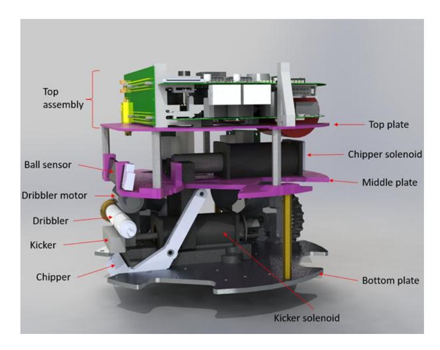
This year the software was only improved based on existing architecture. For this, improvements were made on the quality and stability as well as documentation. The current state of the software can be found on our Github4 . The biggest improvements concern the hardware of the robots. Therefore, the focus of this paper will be on the hardware. The specifications of the current robots can be found in Table 1. Figure 1 shows the current design of the robots.
At the beginning of the year, we decided to slowly transition to a modular hardware design for our robots over the coming few years. A start with this was made by overhauling the front assembly's design, which houses the dribbler and provides damping, and by implementing new solenoids. More details about these changes can be found in Section 3. We also redesigned our bottomboard according to the new modular design. The bottomboard is the circuit board which provided the circuitry for kicking, chipping and dribbling. More information about this can be found in Section 4.
4 https://github.com/RoboTeamTwente
2 RoboTeam Twente
Table 1. Robot specifications:
| Dimension | 179 x 149 mm |
|---|---|
| Driving motor | Maxon EC-45 flat 50 Watt |
| Dribbling motor | Maxon DCX 19s |
| Wheel diameter | 55 mm |
| Wheel gear ratio | 2:5 |
| Encoder driving motors | MILE 1024 CPT |
| Dribbling bar diameter | 10mm |
| Dribbling bar length | 70mm |
| Microcontroller | STM32F767ZI |
| Ball sensor | zForce AIR Touch |
| Motor controller | ROHM BD63002AMUV |
| Inertial measurement unit Xsens MTi-3-8a7g6t | |
| Battery | 6S1P 22.2V LiPo |
2 General Part Hardware
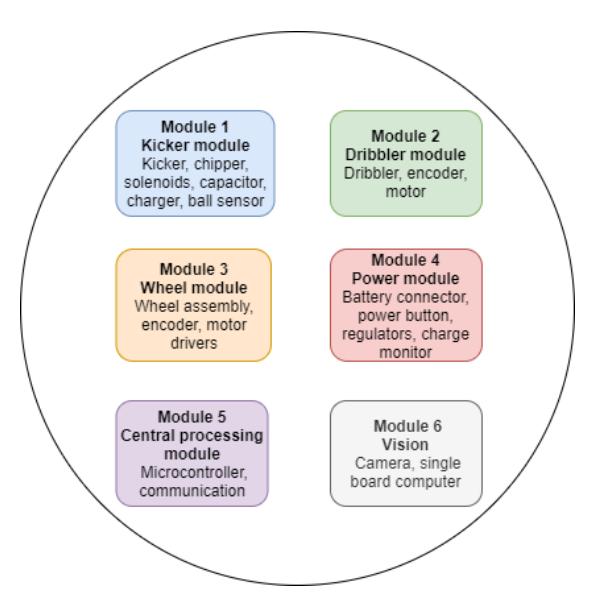
The hardware of the robots is of great importance for their performance and the execution of actions, such as kicking, chipping and dribbling. These actions are currently performed moderately well by the robots. However, experience teaches that the performance is not always consistent and the robots have to be tested regularly to ensure proper performance during events and matches. Investigating malfunctions of the robots and repairing them is time-consuming. In order to enhance their maintainability and repairability, components and functions that belong together were divided over several modules as can be seen in Figure 2. Teams that already designed their robots in a modular way proved that this was a successful way of decreasing the repair time [1]. Having these modules creates the ability to test functions separately. It would be beneficial for the accessibility of certain components in the robot for which it is currently a time-consuming task to repair from a mechanical point of view. Also, a more modular electronics design was chosen because of the aim to design a system that allows efficient troubleshooting, easy replacement of broken components, and that minimizes the probability of failure of components. In Sections 3 and 4, the implications of a modular design from mechanical and electrical perspectives will be discussed.
3 Modifications of Mechanics
The main goal of the mechanics team was to reduce the downtime of the robots. Currently, components that break frequently are not easily accessible, so it is difficult to repair the robots quickly. Last year, the focus was mainly on making the robots more robust and therefore making sure that they break less often. This year, the problem will be approached differently. The goal of this year's mechanics team is to improve the maintainability and repairability of the robots. This will be done by taking the first steps towards a completely modular design for the robots. Since it might not be feasible to implement a modular design for the entire robot in a year, the focus for this year is on the front assembly of the robots, comprising modules 1 and 2, which can be seen in Figure 2.
Secondly, the handling of the ball can be improved. Two major aspects that can be improved are 1) the damping of the front assembly and 2) the use of the dribbler. In the previous version of the robot, sponges were used as damping material for the front assembly [2]. However, this did not work properly since the ball still bounced off of the robot when it tried to receive the ball. Furthermore, the effectiveness of the damping varied for different robots mainly due to the way the sponges were glued to the front assemblies. Also, the use of sponges did not seem to be reliable as they tore easily. During the process of redesigning the front assembly, better damping mechanisms have been investigated. The current damping behaviour has been tested in order to be able to compare new solutions to the previous situation. Additionally, in collaboration with the control team, the influence of the dribbler on the ball handling has been investigated. Possible improvements from a mechanical point of view regarding the dribbler will be taken into account as well. Finally, since the front assembly should be able to function as a separate module, module-specific printed circuit boards (PCBs) will be incorporated in the new design as well.
Damping Tests As mentioned before, the damping behaviour is inconsistent for different robots. Therefore, a robot with reasonable damping and a robot with poor damping have been used in these tests.
3 Modifications of Mechanics - Damping Tests (continued)
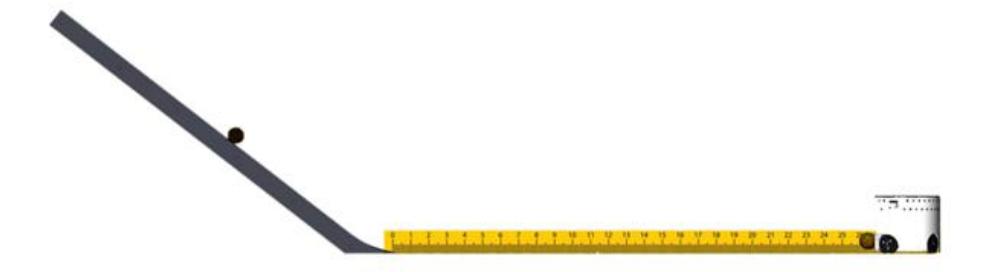
The setup of the tests can be seen in Figure 3. The ball has been dropped from different heights in order to test the damping behaviour for various ball velocities. The approximate velocities that have been used during the tests are 1.0 m/s, 1.5 m/s, 2.0 m/s, 2.5 m/s, 3.0 m/s, 3.5 m/s. The maximum allowed speed for the ball during a game is 6.5 m/s. The measuring tape has been used to see how far the ball bounces back (during the tests, the measuring tape started at the robot and ended at the ramp. So when the ball was caught by the robot, the distance measured was 2.5cm). The tests have been repeated with the two different robots and for different rotational speeds for the dribbler. The rotational speeds of the dribbler are expressed by numbers scaled from 1 to 7, with 7 being the highest.
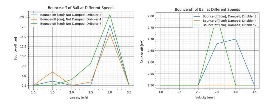
The tests showed that catching the ball seems to work best if the velocity of the dribbler matches the velocity of the ball on the contact surface between the dribbler and the ball, as can be seen in Figure 4. Hence, the angular velocity of the dribbler could be increased gradually once the ball has been caught. This might improve the dribbling when the robot is moving. On the other hand, the backspin on the ball should not be too high when the ball is being kicked. Too much backspin might decrease the distance the ball will roll. Furthermore, the tests showed significant differences between the robot with reasonable damping and the robot that barely had any damping. This can also be concluded from the graphs in Figure 4. In general, the ball bounced off further for the robot with poor damping, as expected.
3 Modifications of Mechanics - Test Conclusions
Several points that have been concluded from performing these tests and have been taken into account in the redesign of the front assembly are the following:
– The importance of great damping should not be underestimated. The tests showed that great damping significantly increased the performance of the robots.
- Different rotational speeds also influence the success rate of the robot catching the ball. This is mainly interesting to implement in the control of the robot or in strategies.
- While doing the tests, the positioning and the lack of support of the dribbler motor sometimes caused damage on the dribbler bar. Therefore, the location of the motor should be changed or it should be better supported.
- Also, the chipper sometimes hindered the ball to reach the dribbler bar properly. Therefore, the chipper should be positioned better.
3.1 Redesign of the front assembly
The mechanism that involves the dribbling, passing and chipping of the ball is denoted as the front assembly. The current design resulted in some problems that limited the dribbling performance of the robots. The main problems were identified in the beginning of this paper. These have been taken into account when considering requirements for the redesign of the front assembly. The points of improvement are the following:
- Design the front assembly such that it is also capable of handling the vertical component of the ball impact forces, since the trajectory of the ball will not be perfectly horizontal.
- High reliability in properly receiving balls.
- Improved rigidity of the front assembly to reduce the amount of maintenance due to loose connections.
- Modular design of the assembly, reducing downtime due to malfunctioning of a component that governs either dribbling, chipping or passing.
- Improved support of the dribbler motor to guarantee parallelism of the shafts that transport torque from the motor to the dribbler bar.
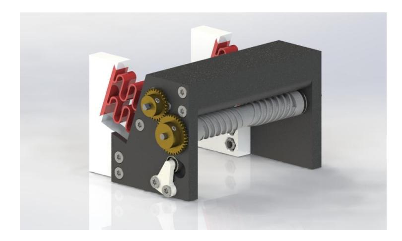
Proposed Design of the front assembly A new front assembly was designed, keeping the requirements mentioned above in mind. A picture of this new assembly is shown in Figure 5.
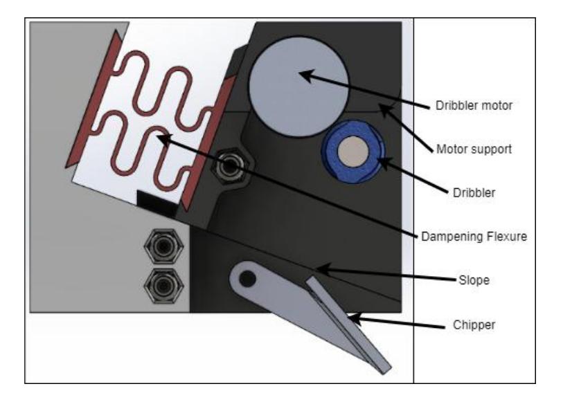
Figure 6 shows a cross-section of the front assembly's new design with its main features. A remarkable change is that, upon impact of the ball, the front part can shift back over a slope instead of only moving horizontally. Therefore, vertical impacts of the ball are taken into account as well. The ball impact is damped by a visco-elastic flexure element, shown in red in Figure 6. This flexure is easily interchangeable due to the dove-tail connection, which allows for testing many configurations of such an element, by changing its geometry and material to tweak the performance of receiving the ball. This is a major benefit over the sponges that were glued to the parts. Furthermore, the flexures, as opposed to the sponges, are more predictable in behaviour. This predictability of the system contributes greatly to the consistency of the front assembly's performance. Therefore, receiving the ball is more reliable with this new design.
Moreover, the bolted connections in the frame are improved by using inlays of self-locking nuts instead of directly screwing in the plastic. This eliminates the problem of wear-out of the plastic around the bolts, hence it improves the rigidity of the front assembly. Also, in the old configuration, the dribbler motor was only fixed on one side which sometimes caused it to fall on the dribbler bar. To prevent this, the new front assembly has been designed such that the support of the motor does not only rely on one connection.
Finally, most of the parts are designed such that they can be produced with a 3D-printer. This way we can make most parts in-house, instead of relying on outsourced products, reducing production times for the assembly. This allows us to easily incorporate new features on the parts, which in the end gives us more control over the design of the front assembly.
3.2 Redesign of the top assembly
In the current design of the robots, the top assembly is the part that contains the PCBs. It is located at the top of the robots, as shown in Figure 1. There were several issues encountered with the 2021 design of this assembly. First, whenever our robots drive, the PCBs on top of the robots vibrate. Also, they are only connected at the front of the robot but are not fixed at the back. These two issues sometimes cause the PCBs to disconnect from the backboard a little bit, which is enough to damage them. Moreover, some cables cannot be unplugged unless the PCBs are also removed, and the top assembly cannot be taken out of the robot unless these cables are unplugged. This is very time consuming when the top assembly needs to be taken out of a robot. Therefore, the top assembly was redesigned in order to reduce the PCBs' vibrations enough to make sure they stay connected to the backboard at all times, and to be able to take the top assembly out of the robot as one module in order to save time.
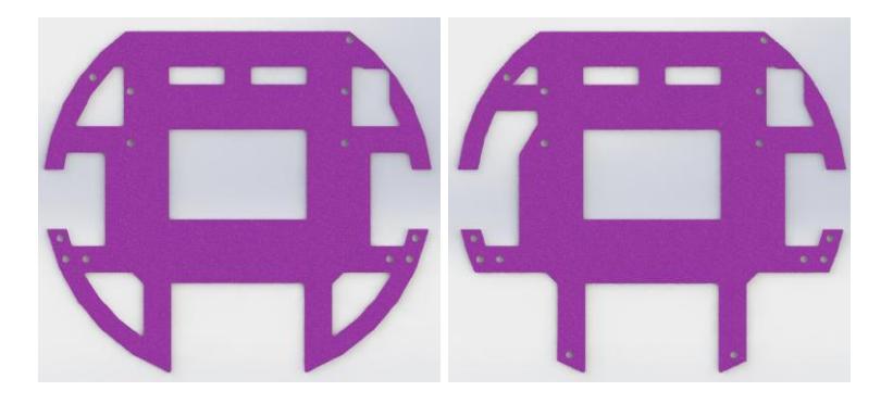
Two different parts of the top assembly were redesigned, the top plate and the PCB holders at the back of the assembly, which can be seen in Figures 7 and 8 respectively. For the top plate, some holes where changed and two additional screw holes were added to better fix it in place. The motor encoder cables as well as the kicker solenoid cable could not be removed without taking the bottomboard out since they had to go through the two holes at the bottom and the one at the top left respectively. Therefore, these holes were changed as shown in Figure 7. Moreover, the back of the top plate was not fixed, therefore the back of the bottomboard could move downward very easily. However, with the new design, the back of the top plate is connected to the middle plate with two metal supports so the bottomboard cannot move downward at all. This already reduces the vibrations a lot, but the PCBs are still able to move upward which is why the PCB holders were redesigned to prevent these upward vibrations.
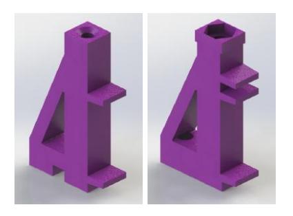
The PCB holders at the back were redesigned in order for the topboard to be slided in the top part, instead of just resting on it like in the previous design, as it can be seen in Figure 8. After putting these redesigned parts in the robots, the topboard cannot move up or down, and the bottomboard is stuck between a fixed topboard and a fixed top plate. Therefore, it can only move by a couple of millimeters which is enough to keep the PCBs in the backboard at all times.
Additionally, the PCB holders are used to fix the cap of the robot on the robot. However, the current PCB holders have 3D printed threaded holes and the caps are often put on and taken out of the robots so the threads wear off very quickly. Therefore, this connection was not reliable and the caps fell off easily. To prevent this, the connection at the top of the PCB holders has been redesigned such that a nut can be slided in it, as shown in Figure 8. This makes the connection with the cap of the robots much more reliable.
3.3 Design of Custom Solenoids
The prototype for the solenoids is designed and tested for the primary use of kicking the ball. Solenoids are chosen because they can provide exceptional force for a compact unit. Using other mechanisms like rack and pinion is possible but would require a large motor with huge power ratings. Another benefit of a solenoid is that it is a pulsed device with minimum components, that optimizes the digital control resulting in high reliability and faster cycling with very few interfaces.
Fundamentally, solenoids are actuators that:
- Generate a magnetic field i.e. acts as a permanent magnet that can have reverse polarity and can be turned on or off.
- Convert electric current (i) to mechanical work (Force)
Solenoids are constructed as a wire wounded in the form of a coil around a magnetic material. The coils are in general made in the shape of a helix because this shape generates a controlled magnetic field. The solenoids work on a principle of self inductance. When a current flows through the wire, a nearly uniform magnetic field is generated. The field strength depends on the current and varies when this changes. A change in the magnetic field varies the magnetic flux that induces an electromotive force (voltage) to oppose the change in current. When a conductor is placed between the coil, magnetic field lines are formed in and around the coil which moves the conductor.
Construction of the Solenoid In the current design, off-the-shelf solenoids are used to actuate the kicker and the chipper. These solenoids are rather big, which is a disadvantage since the available space is very limited. Therefore, new solenoids have been designed. These custom made solenoids have smaller dimensions and might replace the solenoids currently used if tests prove them reliable and of sufficient quality. The space that will become available can then be used by other systems of the robots in the future. Furthermore, the different placement of the solenoids might lower the center of mass of the robot which would in turn give us the possibility to increase the maximum acceleration.
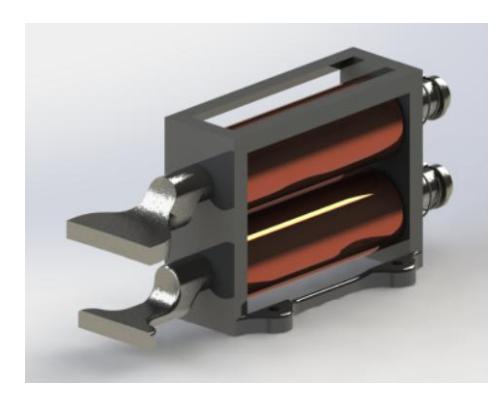
The new solenoid is constructed with copper wires wound around a 3D printed hollow cylinder. A conductor made of cast iron called the plunger is placed in the hollow cylinder and allowed to move under the effect of a magnetic field. The conductor is placed inside the coil because the magnetic field outside the solenoid is approximately zero [3]. To return the plunger back to its neutral position when the solenoid is deactivated after actuation, a compression spring is used. A render of the solenoid is shown in Figure 9.
The new design of the solenoids is implemented to lower the center of gravity of the robot in order to stabilize the robot in addition to compact design. A part of the old solenoids was on the middle plate which shifted the center of gravity of the robot upwards. The new solenoids are located between the middle plate and bottom plate, hence they brings the center of gravity downwards. Another advantage of the new solenoids is a better torque for the chipping mechanism. The old solenoids used a big arm that restricted the stroke length of the plunger and extra force was required to chip the ball. The new solenoids can chip the ball directly and in a more intuitive way of naturally kicking the ball similar to human kicking the ball. The current solenoids will also allow to control the speed of the plunger much better with a higher bandwidth than the previous solenoids.
Table 2 discusses the parameters of solenoid used to construct the solenoid.
| Parameter | Symbol | Value |
|---|---|---|
| Length of the coil | Lcoil | 45mm |
| Diameter of the coil | dcoil | 0.80 mm |
| Diameter of the plunger | dp | 10 mm |
| Mass of the plunger | mp | 46.63 g |
| Mass of the ball | mb | 45.60 g |
| Inertia of the ball | J | 0.331 ×10⁻⁶ kgm² |
| Angular velocity of the ball | ωb | 304.45 rad/s |
| Maximum extension of the spring xe | 300 mm |
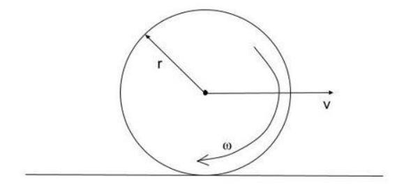
Design Requirements Figure 10 shows the ball while it is rolling. At this time the ball contains translational and rotational kinetic energy. The total energy in the ball is the sum of the translational and the rotational kinetic energies.
$$E_{ball} = \frac{1}{2}m_b v_b^2 + \frac{1}{2}J\omega_b^2$$
$$E_{ball} = 0.407J$$
Neglecting friction and using conservation of energy, the required velocity of the plunger is calculated as:
$$\begin{split} E_{plunger} &= E_{ball} \ E_{plunger} &= \frac{1}{2} m_{plunger} v_{plunger}^2 = 0.407 \ v_{plunger} &= \sqrt{\frac{0.407}{\frac{1}{2} m_{plunger}}} \ v_{plunger} &= 4.179 m/sec \end{split}$$
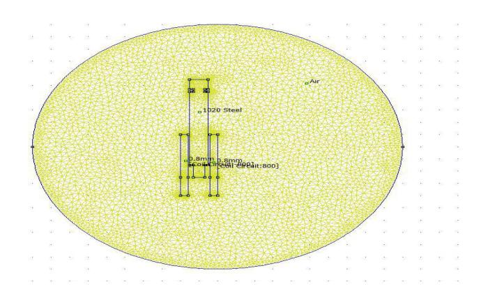
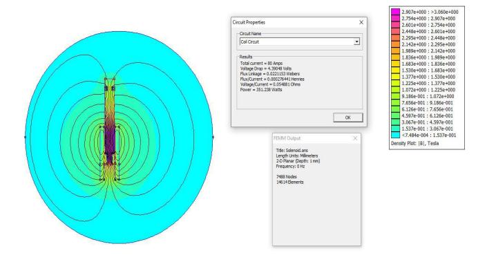
FEMM Simulations FEMM is a program for solving low frequency electromagnetic problems on two-dimensional planar and axisymmetric domains [4]. In Figures 11 and 12, the simulation of the solenoids and the magnetic field density are shown in FEMM software respectively.
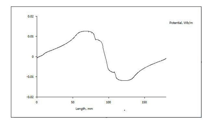
In Figure 13 the variation of the potential with respect to the length of plunger is shown. This shows that for a 0.80mm AMG wire, the magnetic flux is highest when the length of the plunger is equal to 80 mm. The force of the plunger is given by:
Force = magnetic flux × reluctance
Hence, when the magnetic flux is at a maximum, the force will be maximum. The number of turns are found by trial and error. It is observed that after 500 turns the force decreases due to increase in reluctance.
4 Modifications of Electronics
As mentioned before, the main goal of this year is to make the robot more reliable by avoiding hardware failures. Currently the robot contains two PCBs. One which contains most of the components needed for control and communication and one which is responsible for the control of the dribbler and the solenoids. The latter, also called the bottomboard because of its position within the robot, is being fully redesigned. It was noticed that when electronics fail the robot, most of the time it is because of the bottomboard.
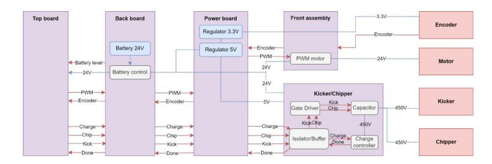
As the robot is mechanically being broken up into different modules, as seen in Figure 2, the electronics will also be following this same subdivision. For the bottomboard this will mean that it will be split into three modules, into electronics related to the dribbler, kicker and chipper, and power module.
The two PCBs mentioned above are interconnected using a third PCB called the backboard. In addition to the changes of the bottomboard, the back board will also be redesigned, with most noteworthy an addition the implementation of a digital voltage meter.
To achieve the goals regarding modularity, a design was envisioned that will operate on a plug-and-play style, utilize a new array of more efficient integrated circuits, and be built with simplicity in mind. Figure 14 shows the electronics' plan for the modular design.
4.1 Kicker and Chipper Module
When the bottomboard breaks, often it is because of the kicker and chipper part of the bottomboard. This is due to the influence on the electronics from the kicker and chipper solenoids. The main task of the kicker and chipper module is to control the charging of the capacitor of 680 µF to 450 V . This is done by a booster circuit consisting of a charger controller and flyback transformer.
The topboard is responsible for exciting one of the two solenoids, to kick or chip a ball. It does this by executing a kick or chip command, that goes to the kick or chip module through the back board. This activates one of the two MOSFETs that allow energy stored in a capacitor to discharge across the kick or chip solenoid. Before reaching the MOSFETs, these commands go through an additional gate driver and buffer/line drive. This is a component that most often breaks down resulting in the kicker or chipper not working.
Additionally, a magnetic field is generated by the discharged current from the capacitor, which can reach up to 80A. This generates voltage spikes on the kick and chip signal lines. In some cases, spikes are also observed on the power lines, which damages the low voltage regulators and the mentioned drivers, see also [5]. Additionally, the topboard suffers from noise that is generated by the high-frequency flyback converter that charges the capacitor.
To limit the influence of the kicker and chipper module, attention has been focused on the close decoupling of the components, and power and signal lines/areas. Additional safety components are added, such as diodes, and new components are selected that are better suited for the current circuit and its issues. The modular design will be a great asset to ensure the kicker and chipper work, because of the easy PCB exchange.
4.2 Dribbler Module
The main change for the dribbler module is the addition of the encoder for a Maxon DCX dribbler motor, allowing for more precise speed control. This control is done by using a MOSFET opening and closing to supply the needed voltage for the motor [6]. A pull-down resistor is added to have a steady state.
4.3 Power Module
A third PCB module is responsible for regulating voltages, other than the 24 V , required by the other PCBs. Compared to the old design, which used linear voltage regulators, the new design utilises buck converters.
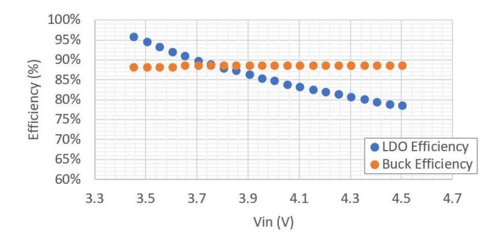
Low dropout regulators (LDO) regulate a voltage by controlling a linear component such as a resistor. This is inefficient because power is lost as heat. Contrary, power converters uses a switching element to transform the incoming power supply voltage into a pulsed voltage [7].
As Razavi [8] illustrates, power is supplied from the input to the output by turning on a MOSFET, until the desired voltage is reached. Then turn the switch off for the rest of the time period, generating a pulse voltage. The output voltage is then smoothed using capacitors and inductors. Once the output voltage reaches the predetermined value the switch element is turned OFF and no input power is consumed. As a result we have a much better efficiency next to the efficiency of a LDO.
Furthermore as we figured out while testing, LDO power modules often tend to break. This might be because there is no extra protection circuit or because the regulators have to dissipate a lot of power through heat. The new design will come with Cycle by Cycle current limit, Hiccup mode short-circuit protection and thermal shutdown in case of excessive power dissipation. All these extra features are implemented into the new integrated circuit (IC) which will be responsible for the conversion.
4.4 Other Improvements
Previously, an analog voltage meter was implemented on the back board. Its goal was to monitor the battery voltage, such that a battery change can be preformed in time. This year a digital battery management system will be implemented.
Also, new batteries are selected to anticipate on the current ones used being discontinued.
Until now, the ball sensor, as introduced in 2019 [9], works good. However, it is connection is not robust against shaking, hence, oftentimes disconnects making it unusable. To improve the stability of the connections, a new small PCB has been designed where proper connectors were added for solid connections.
References
- TIGERs Mannheim: Extended team description paper 2020 (2020)
- RoboTeam Twente: Extended team description paper 2020 (2020)
- http://www.etymonline.com/index.php?term=solenoid
- https://www.femm.info/wiki/Documentation/
- Tang, Y., Blaabjerg, F.: A component-minimized single-phase active power decoupling circuit with reduced current stress to semiconductor switches. IEEE Transactions on Power Electronics 30(6), 2905–2910 (2014)
- Scherz, P., Monk, S.: Practical electronics for inventors. McGraw-Hill Education (2013)
- Huang, C.H., Ma, Y.T., Liao, W.C.: Design of a low-voltage low-dropout regulator. IEEE Transactions on Very Large Scale Integration (VLSI) Systems 22(6), 1308–1313 (Jun 2014). https://doi.org/10.1109/TVLSI.2013.2265499
- Razavi, B.: The low dropout regulator [a circuit for all seasons]. IEEE Solid-State Circuits Magazine 11(2), 8–13 (2019)
- RoboTeam Twente: Extended team description paper 2019 (2019)