SRC Team Description Paper for RoboCup 2022
He Yan, Yuhao Li, Xingyao Han, Haobo Zhang, Siyuan Chen, Yangyang Feng, Zikang Shi, Yunlang Zhou, Yujia Zou, Rui Shi
Student Innovation Center, Shanghai Jiao Tong University, P.R.China
Abstract This paper introduces the improvement of our team in trajectory planning, speed estimation, dribbling mechanical structure, and kicking system. We hope to do well in RoboCup 2022 with these improvements.
Introduction
We are the SRC Team of Shanghai Jiaotong University. We had our first small-size league competition in 2015. Since then, we have been locating problems and discussing where we can improve. In the past year, on the hardware side, we have optimized dribbling and kickball gear for higher ball possession rates and larger fields. Besides, we have optimized Kalman filtering for speed estimation and used B-splines for trajectory planning. We'll describe the improvements we've made over the last year later.
Hardware
Hardware improvements and technical details follow in subsections.
2.1 Mechanics
Our hardware has undergone numerous changes since the 2020 competition. [2] After the practice in the games, we found that the mechanical structure used before was insufficient in many aspects. Our robot cannot achieve very stable ball suction and the horizontal distance of our chipping mentioned in last year's paper was unable to meet the demands of larger venues for competitions.
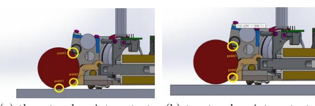
In response to these problems, we have improved the existing mechanical structure. The first is the ball-picking device. We refer to the three-touch-point ball contact model proposed by ZJUNlict [1] and modify the shape of the ball picking mechanism. Figure 1 shows that our vehicle can now achieve two modes: two-touch-point contact and three-touch-point contact.
When the ball touches the robot, the ball is in a three-touch-point contact state (Fig 1(a)). In this state, the ball is in contact with the ground, the roller, and the ball-picking device concurrently. After picking the ball for a while, the ball is lifted and reaches a two-touch-point contact state. It is then only in contact with the roller and the ball-picking device (Fig 1(b)). During the transition between the two contact states, the frictional force on the ball greatly decreases. However, when the ball is in two-point contact, friction is too small to lift the ball, so it will fall and return to the three-touch-point contact state. Such state transition occurs continuously, resulting in a relatively stable state. To satisfy the process, we had modified the surface roughness of the contact surface between the ball picking structure and the ball, using 7075 aluminum alloy instead of steel.
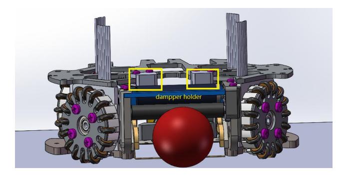
After changing the shape of the ball-picking structure, we have conducted many trials. Although the new device is more stable than the original one, the ball is still bouncing vigorously, resulting in ball escape in some circumstances. In order to buffer and absorb the bouncing, we added a 3D-printed component to the existing mechanism (Fig 2). This component helps to support the sponge damping mechanism with adequate elasticity and buffers the shock, thereby improving the stability of the whole device.
After the above mechanical modification, the overall stability of our robot has been greatly improved. However, some problems still exist. For example, the ball sometimes deviates from the center and cannot follow the planned shooting route. We are going to modify the mechanical structure and solve the newly exposed problems in 2022.
2.2 Circuits
The power board contains a BOOST converter circuit and its protection circuit, which handles the high-current components of our robot. A set of capacitors used for kicking are charged through the BOOST converter to a high voltage.
The UC3843 is used to control the BOOST converter to charge capacitors from 0V to the high output voltage in a few seconds. The output voltage is set through the voltage-feedback pin (VFB) on the UC3843.
In our last version, we increased the output voltage from 138V to 214V, and the improvement is significant: The chip distance of the new system can now reach 4m, 120% farther than the previous prototype [2].
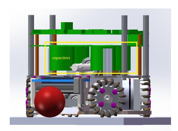
However, new design brings new difficulties. In our designs, the capacitors are placed beneath the power board laying upon the solenoid, as shown in Fig 3. As the voltage increases to 214V, the size and weight of capacitors increase, and our robots are much easier to roll over at a high speed. We realize that the high center of gravity of the current design has become an important factor limiting our performance. We are working on modifying the mechanical design to lower the center of gravity.
2.3 Electromagnets
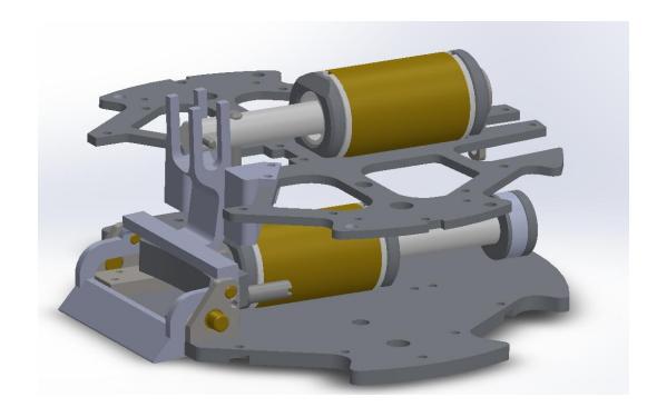
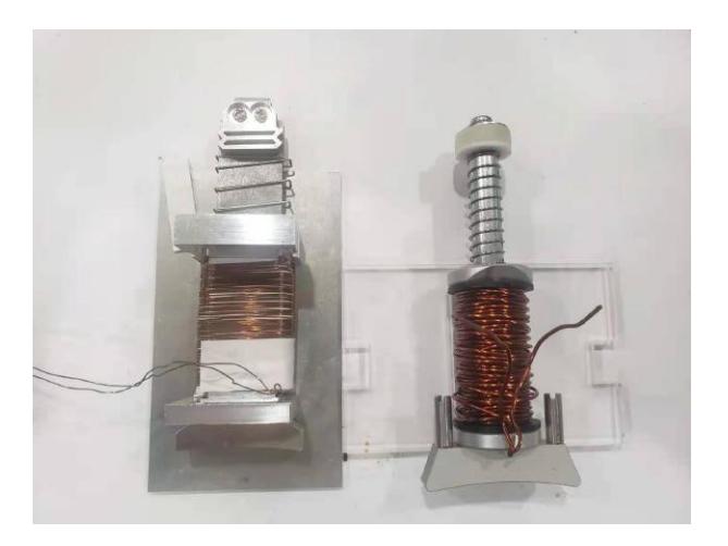
The current electromagnets on our vehicles are too clumsy: it consists of two cylindrical coils, vertically assembled with the upper one for chip-shooting and the bottom one for flat-shooting (Fig 4). It occupies too many space in the vehicles and lifts the center of gravity. Moreover, the coils for the chipping mechanism are too high, so we need an additional gearing system to drive the chipping. Therefore, we hope to redesign our coils into cuboid shapes. It requires us to look for new mechanical and circuit designs.
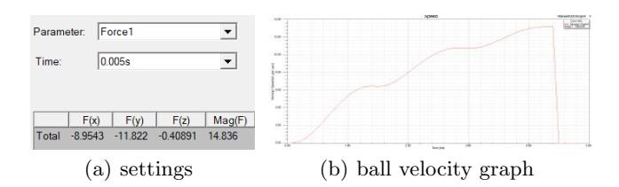
We have been taking references on the models open-sourced by TIGER[3] and ZJUNlict[1]. First, we designed the components and performed the simulation on Maxwell. In Maxwell, we have tested different parameters, i.e., coil materials and diameter of wires. As shown in Figure 5(b), in the period of 5ms, our structure made of copper coil wires and 1008 Steel soft magnets could strike a ball with a velocity equal to 13.2m/s, without considering gravitational potential and friction. It would be sufficient for our scenario, in which the ball speed limit in the game is 6.5 m/s.
After the simulation, we have manufactured a prototype (Fig 6). It achieved similar results to the original ones when the flat-shoot reached velocity at 8.15 m/s and the chip-shoot reached distance at 3.5 m. However, the power board cracked soon after a few shots. It is due to the inductance of the coils. The new inductance (81.21 uH) was 16 times smaller than the old one (1365.1 uH), so the current was 16 times larger. We are still handling the differences, so it is not implemented into our robots yet.
Software
Software improvements and technical details follow in subsections.
3.1 State Estimation Based on Kalman Filter
The state estimation algorithm we currently use mainly utilizes the visual information fed by SSL-Vision, and the influence of environmental noise is weakened by Kalman filtering to finally obtain the real-time position and velocity.
Since the robot motion has a strong linear and Markovian nature, we use a linear Kalman filtering algorithm with only the previous moment's position and velocity input. Subsequent experiments found that better results were obtained using a motion model with uniform acceleration where the acceleration is calculated using the velocity of two consecutive frames.
In order to test the performance of our Kalman filter in the actual state estimation, we select three typical test scenarios, namely Static Position Estimation, Dynamic Position Estimation and Fixed Velocity Estimation.
Our noise parameter settings are as follows:
$$P = \begin{bmatrix} 5.0 & 0 & 0 & 0 \ 0 & 5.0 & 0 & 0 \ 0 & 0 & 5.0 & 0 \ 0 & 0 & 0 & 5.0 \end{bmatrix} \qquad R = \begin{bmatrix} 10 & 0 \ 0 & 10 \end{bmatrix}$$
Our init Q, A and B is as below:
$$Q = \begin{bmatrix} 0.4 & 0 & 0 & 0 \ 0 & 0.4 & 0 & 0 \ 0 & 0 & 0.4 & 0 \ 0 & 0 & 0 & 0.4 \end{bmatrix} \qquad A = \begin{bmatrix} 1.0 & 0 & dt & 0 \ 0 & 1.0 & 0 & dt \ 0 & 0 & 1.0 & 0 \ 0 & 0 & 0 & 1.0 \end{bmatrix} \qquad B = \begin{bmatrix} 0.5dt^2 & 0 \ 0 & 0.5dt^2 \ dt & 0 \ 0 & dt \end{bmatrix}$$
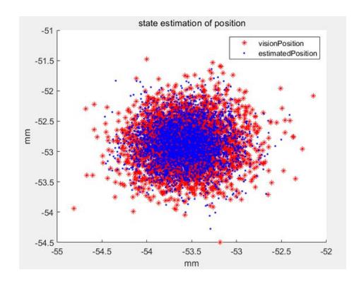
Static Position Estimation Our first test scenario is Static Position Estimation. Fig. 7 demonstrates the ability of the state estimation algorithm to filter out environmental noise. We place the robot stationary at a point with coordinates of approximately (−53, −53.5), after which the collected raw visual data and the filtered results are plotted for comparison, with the red dots representing the raw visual data and the blue dots representing the filtered results. It can be seen that both sets of data are roughly Gaussian distributed, and the center point is close to the real position. The filtered results are more concentrated, and the distance from the center point is generally no more than 0.5 mm, which reduces the effect of noise significantly.
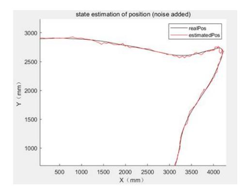
Dynamic Position Estimation Our second test scenario is Dynamic Position Estimation. This is the result of the position estimation during the motion of the robot. This experiment was conducted in a simulation environment, with the black line data taken from the physical simulator, representing the real motion trajectory, and the red line being the curve made from the filtering results. The ambient noise in the simulator is set to the maximum value, and the results are still very good, and the filtering results always match the real values.
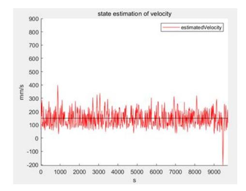
Fixed Velocity Estimation Our third test scenario is Fixed Velocity Estimation. The robot was controlled to move at a uniform speed of 1.6 m/s and the filter results were collected in real time to connect the curves. It can be seen that the estimated velocity keeps fluctuating around the true value due to environmental noise, but the magnitude is small and does not exceed 1 m/s most of the time, which can be used as a reference for subsequent motion planning.
3.2 Trajectory generation using B-splines
We realized that all plays can be dissembled to a motion task: move to a target state without collision. The faster robot can finish such motion task, the quicker the team builds up threat or solidify defense.
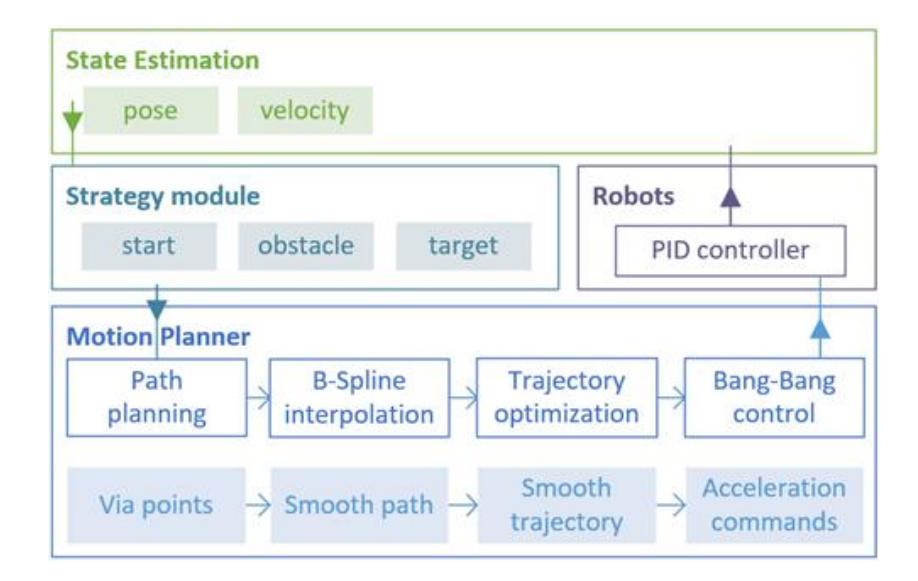
We use quasi-uniform B-spline to interpolate RRT(Rapidly-Exploring Random Tree) results. Poor continuity of RRT-generated path affects the feasibility of the trajectory, which slows down traversing between obstacles severely. To enhance path continuity, we introduce B-spline into our framework to interpolate a smooth path based on RRT results. Details of the framework are illustrated below:
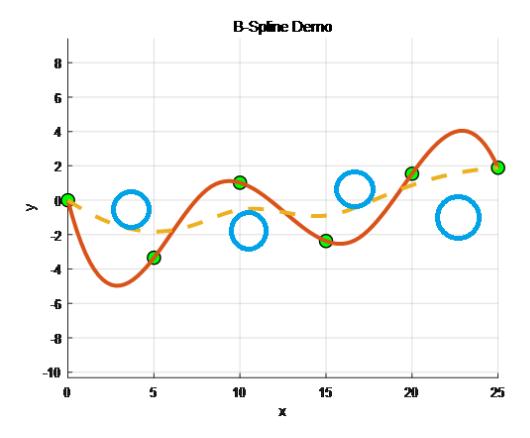
Fig.11 illustrates B-spline interpolation example. Blue circles are obstacles. Green dots are RRT-generated path points. If interpolate the B-spline with the path points as the control points, the result mostly collides with obstacles, shown with dotted line. However, with the control points inversed, the path swerve around the obstacles, maintaining a collision-free and smooth path, shown in full line[4].
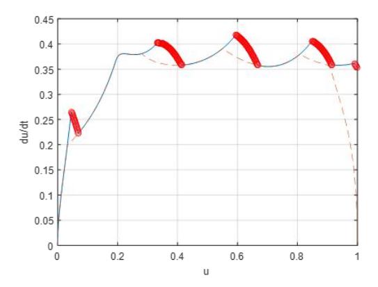
Furthermore, the bidirectional scan algorithm and bisection search are implemented to generate maximum speed under the kinematic constrains. This allows us to optimize our trajectory.
Fig.12 is the parametric velocity profile calculated by bidirectional scan algorithm. The blue graph is the result of forward scan. The red dashed graph is the result of backward scan. The red scattered points are discontinuities introduced in forward scan. It can be seen that the discontinuities are fixed with backward scan.
The result demonstrates that our approach outperforms existing trajectory planning methods:
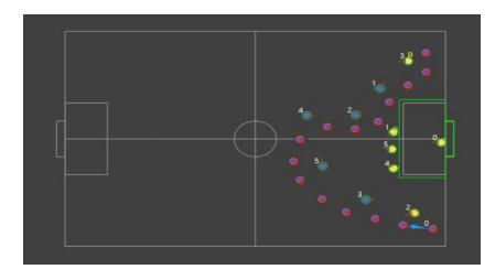
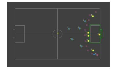
Fig.13 represents the-state-of-the-art, which accelerated too fast at the beginning and missed the cut-in chance. Fig.14 is our method, considering the turn constraint and slowed down in advance.
Conclusion
In the previous sections, we introduced our development efforts from the hardware and software sections respectively. In the hardware part, we mainly studied the new three-point ball contact mechanical structure, the new power plate and electromagnet. In the software part, we mainly studied using Kalman filter to improve the performance of state estimation, and generating Bessel curve to plan path. Through these changes, our soccer robot has better performance, and we expect our soccer robot to have better performance on the field.
References
- Zheyuan Huang, Lingyun Chen, Jiacheng Li, Yunkai Wang, Zexi Chen, Licheng Wen, Jiangyang Gu, Peng Hu and Rong Xiong, ZJUNlist Extended Team Description Paper for RoboCup 2019. In RoboCup 2019 (2019)
- Jiawei Lin, Jie Chen, Baiji Chen, Kaichong Lei, Zikang shi, Jiaping He, Zhengwei Qin, Jiaxuan Xie, Jingwei Xu, Zhaocong Liu, Ruiqing Ge and Li Hao, SRC Team Description Paper for RoboCup 2020. In RoboCup 2020 (2020)
- Andre Ryll, Sabolc Jut, TIGERs Mannheim Extended Team Description Paper for RoboCup 2020. In RoboCup 2020 (2020)
- M. M. Heng, "Smooth and time-optimal trajectory generation for high speed machine tools," Optimization, p. 136, 2008.