TIGERs Mannheim - Extended Team Description for RoboCup 2022
Nicolai Ommer, Andre Ryll, Mark Geiger
Department of Information Technology Baden-Württemberg Cooperative State University, Coblitzallee 1-9, 68163 Mannheim, Germany
Abstract This paper presents a brief overview of the main systems of TIGERs Mannheim, a Small Size League (SSL) team intending to participate in RoboCup 2022 in Bangkok, Thailand. This year, the ETDP will focus on debugging and testing of our AI. After over 10 years of developing our central software, we would like to share our experiences and the current strengths and weaknesses of our open sourced software framework. We also give a short update on our latest robot generation and last but not least we introduce how we utilized our dribblers to score goals, which played a crucial part in winning the 2021 RoboCup.
1 Robot Hardware Updates
This year, we made two minor improvements to our existing v2020 robots. Firstly, the dribbler damping structure has been updated for better dribbling performance. Secondly, our new pattern identification system has proven to work well and is explained in detail. All electronics have remained unchanged. The full mechanical and electrical specifications can be found at the end of this section in table 1. A detailed description of our v2020 hardware can be found in [1,2].
1.1 Dribbler Damping
Good ball control by dribbling is gaining more and more importance in the SSL. The initial v2020 robots used a hinged dribbler with a single rotational degree of freedom. It is based on ZJUNlict's design [3]. It uses a top damper to absorb ball impact energy and a bottom damper to reduce vibrations during dribbling. Although we tested different damping materials and strengths we were not able to achieve ZJUNlict's performance in dribbling. The ball handling during forward/backward motion is good enough for ball placement and uncontested straight moves (e.g. keeper ball handling in the defense area) but during lateral movement the ball is lost easily. The exact cause for the difference in dribbling performance is still under investigation.
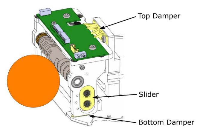
To improve our dribbler we decided to use a design with two degrees of freedom, as we did in our v2016 robots [4]. Figure 1 shows the updated structure. We combined the v2016 2-DoF dribbler with ZJUNlict's additional dampers. The top damper is mainly used to absorb impact energy of incoming passes. As soon as the ball is actively controlled the exerted backspin on the ball can push the whole dribbler upwards on the sideward sliders. If the dribbler drops during the dribbling process (either due to a skirmish or an uneven ground) it is damped via the small bottom dampers. All dampers are 3D printed from a flexible TPE material with a 70A shore hardness. The damping properties of the top damper can be adjusted by changing its shape (mainly by varying the branch thickness).
With the modifications we can now receive passes and control the ball very well. The control performance was mainly evaluated by using the dribbling parcours of the RoboCup 2021 Hardware Challenges¹. Ball reception was assessed visually by the amount of rebound during a reception. It is interesting to note that we dribble the ball very slowly, sometimes the ball even stops and enters a clamped state. The clamping only happens in one direction, lateral movement is still possible and thus we are not removing all degrees of freedom from the ball (which is forbidden by the rules). The material of the dribbling bar itself is very soft and abrasive. Hence, we actually cannot dribble the ball with high speed for a long period of time.
Although our dribbling has been improved and we also won the 2021 dribbling hardware challenge we are still looking to improve our dribbling performance further. Especially the soft and abrasive dribbling bar material is a drawback as it requires regular maintenance. Furthermore, we cannot make chip kicks with much backspin. We hope to address this issue by using a more robust material like silicone, which we have not tested yet with this updated 2DoF structure.
1.2 Pattern Identification System
The new pattern identification system can identify if the robot currently has a cover on it and which pattern ID this cover has. This greatly simplifies robot and cover handling and also allows to implement additional safety features.
In our architecture the cover pattern and the wireless ID of a robot are directly related. Our wireless base station addresses robots individualy and only forwards position data for this specific robot from SSL-Vision. This means it is essential for our robots to have a matching wireless ID and pattern or the internal robot position control will not work.
We already have a touch display on our robots to set the wireless ID. Nevertheless, in the rush of a match there is little time to do this. Looking for the specific cover matching the wireless ID also takes time. In the worst case the touch display is broken and there is no easy way to change the wireless ID or to find out the current one. Hence, we decided to implement a new system to automatically identify the cover pattern of a robot.
The new system is a PCB on the very top of the robot as shown in Fig. 2. It consists of five TCS34725 color sensors. Each one is paired with a bright neutral white LED. The sensors are attached via an I2C muxer to the primary microcontroller. The inside of our cover now also has small cutouts for each color blob. The cutouts match the positions of the color sensors. Once the cover is placed on the robot it turns on the white LEDs to illuminate the color blobs and reads out the reflected color from the sensors. The identification works very robustly as there are only four colors to separate.
To change the team color of a robot the paper for the central blob can be pulled out towards the cover's front. This paper is yellow on one side and blue on the other. It just needs to be flipped. The robot knows it sees the underside of this paper and will identify a yellow team color when it reads out blue and vice versa.
With this new system it does not matter any more which cover is at hand. Any cover can be placed on any robot and it will adapt. The color sensors can also sense ambient light conditions. Only when ambient light changes significantly a new identification process is started. Furthermore, this also allows us to detect if a robot currently has a cover or not. This can be used for additional safety features (i.e. only charge the kicker with a cover in place). Currently, we use it to enable our wireless interface on the robot. It is inactive as long as there is no cover. This allows us to switch on a robot and perform tests without interfering with our other robots actively participating in a match.
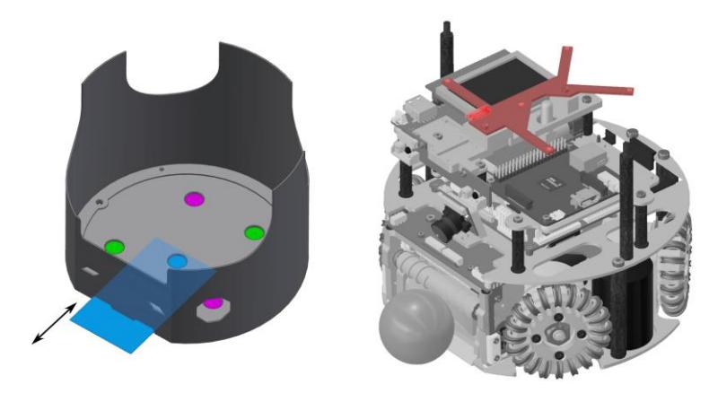
Table 1: Robot Specifications
| Robot version | v2020 |
|---|---|
| Dimension | Ø178 x 148 mm |
| Total weight | 2.62 kg |
| Max. ball coverage | 19.8 % |
| Locomotion | Nanotec DF45L024048-A2, 65W², Direct Drive |
| Wheel diameter | 62 mm |
| Encoder | iC-Haus iC-PX2604 + PX01S, 23040 ppr [5] |
| Dribbling motor | Moons' Industries ECU22048H18-S101, 55W |
| Dribbling gear | 1 : 1 : 1 |
| Dribbling bar diameter | 11.5 mm |
| Kicker charge | 3600 µF @ 240 V (103.68 J) |
| Chip kick distance | approx. 3.6 m |
| Straight kick speed | max. 8.5 m/s |
| Microcontroller | STM32H743 @400 MHz [6] |
| Sensors | Encoders, Gyroscope, Accelerometer, Compass, Camera |
| Communication link | Semtech SX1280 @1.3 MBit/s, 2.300 - 2.555 GHz [7] |
| Compute module | Raspberry Pi 3A+ with one forward oriented camera³ |
| Power Supply | Li-Po battery, 22.2 V nominal (6S1P), 1300 mAh |
2 Software Framework
Our software framework is called Sumatra and is written in Java. We use it since the first participation at RoboCup 2011 in Istanbul and published it after every RoboCup since then. It includes everything running on the computer next to the field, including the artificial intelligence and a UI for visualization. Furthermore, it includes numerous tools to make it easier to develop and test the robots and the AI. This section aims at giving an overview of what we added to the framework in order to analyze and improve the behavior of the AI and the robots over the last ten years and our experiences with it.
2.1 Built-In Simulator
We started with our own implementation of a dedicated simulator, backed by a physics engine. Later, we replaced it by grSim[8], which uses a physics engine as well. This is very useful for testing low level control, but it is by far not as realistic as testing with a real robot. In 2013, we moved all the low level control to the robots and started controlling the robots by sending target positions instead of velocities [9]. Since then the development and testing of the robot control was done outside of Sumatra. The focus in Sumatra moved solely to the AI.
AI developers want to focus on the high level decision making, so we decided to idealize the simulation of the robots and the ball. This makes it easier to verify if calculations are correct and to have a better reproducibility. The simulation is implemented natively in Sumatra. Simulated robots and the ball use the exact same trajectories the AI assumes, so the robots drive exactly as commanded and the ball behaves as expected. The collision model is in 2D (with some special cases for flying balls) to reduce complexity.
Having the simulation implemented natively in Sumatra has several advantages. It can easily be debugged and extended. When running into a breakpoint in the AI, the simulation can be paused as well. Furthermore, there is a small history buffer which allows to step backwards and rerun a situation as often as desired. This, in combination with the ability to hotswap code in Java into the running JVM makes it fast and easy to change and test code.
The simulation speed is coupled with the AI, so the AI can process every frame, even if the underlying hardware is too slow. In this case, the simulation speed will simply be slower. If simulation speed and AI speed are decoupled, the behavior would depend on the hardware, because on slower computers, the AI would compute on less frames and would thus loose input data. Additionally, the simulation can also be run as fast as possible. No need to simulate a game in real time.
Having an idealized simulation has its downsides as well. Things do not always work in practice, mainly because the precision is much worse in reality. We have to test and tune the code on the field as well. Nevertheless, we found this is a very good compromise considering the ease of developing which we currently have.
For RoboCup 2021, we integrated the new SSL simulation protocol⁴ which was required for the virtual tournament. It took a lot of effort to get the robot control right, which is normally done by our robots, but with some extra trajectory synchronization control code it worked quite well. So now we can also optionally run our software with grSim or the ER-Force simulator. A comparison of the three simulators is listed in table 2.
Table 2: Comparison of the Sumatra simulator vs. other open-source alternatives
| Sumatra Sim | – Robots move as expected
– Custom movement skills can be implemented
– Step-by-step simulation, pausible and adaptive speed
– Debuggable natively | – Cannot be used to test low-level robot control
– Robots may behave different in reality |
| grSim | – Stand-alone simulator with UI
– Uses a physics engine
– Implements ssl-simulation-protocol | – Only real-time simulation
– High CPU usage
– Velocity commands only
– Blackbox (from Sumatra perspective) |
| ER-Force Sim⁵ | – Uses a physics engine with focus on realistic modeling
– Implements ssl-simulation-protocol | – Velocity commands only
– No UI
– Blackbox (from Sumatra perspective) |
2.2 Visualization
Visualizing what is going on in the AI is really important for developers. We actually consider this functionality one of our key features for our success and fast adaptions between matches. When we write complex calculations and algorithms, it can be hard to write unit tests, especially while experimenting. Quickly verifying the results in the visualizer interactively helps a lot.
Shape Types To address the flexibility while keeping usage simple, we arrange visualizations in so called shapes. There are some standard shapes, like point, line, circle, rectangle, triangle, tube, ellipse, arc and quadrilateral. Additional custom shapes can also be added, like a trajectory path for path planning or a bot shape for oriented 2D robots. It is also possible to draw text, so called annotations anywhere, or border text for text that is attached to the window border instead of the field.
Animated shapes are addressed as well: They paint the shape based on the system time, so it is possible to create rotating and pulsing shapes. This also works when pausing the simulation or a replay. The most prominent usage example is the rotating crosshair around the ball. The ball is very small and very important. Hence, we wanted to have a way to quickly find it and this is a satisfying solution for many years now.
Shape Organization Shapes are grouped in categories and layers to reduce visual clutter in the UI and to ease selection. Figure 3 shows how categories are presented as a drop down menu and layers are individual entries in the visualizer UI. Each layer can contain an unlimited number of shapes to be drawn.
Shape layers come from different sources, for example from AI, vision filter, robot skill thread, and many others. To make it easier to focus on the shapes that are of actual interest for a specific task they can be disabled by source as well. Furthermore, a developer can also select if a layer should be persisted (see 2.3). A layer can always be persisted, never persisted, or only persisted when Sumatra is running in debug mode.

2.3 Recording Data
We found recording data during a match essential. Without having sufficient data about what was going on during a match, we could not learn from our mistakes and could not improve over time. Having a good recording and replay functionality in the software framework is also very helpful during development and when testing on the actual field, because situations and bugs are often hard to reproduce and most behavior is impossible to understand in real time.
There are some points to be considered when it comes to recording and replaying data:
- The amount of data (disk space)
- The processing overhead for capturing and saving data (RAM and CPU)
- Defining and extending the data schema
- Compatibility to older data
- Loading the data and quickly seeking through it
- Reproduce the world state at any given time
Implementation Sumatra uses an object database (Berkeley DB for Java⁶) for many years now. It requires a significant amount of disk space. A normal game requires a few gigabyte of data, but that data can be compressed to some hundred megabytes afterwards. We never had significant issues with the amount of data. With modern hardware, there is no reason to work on reducing the data.
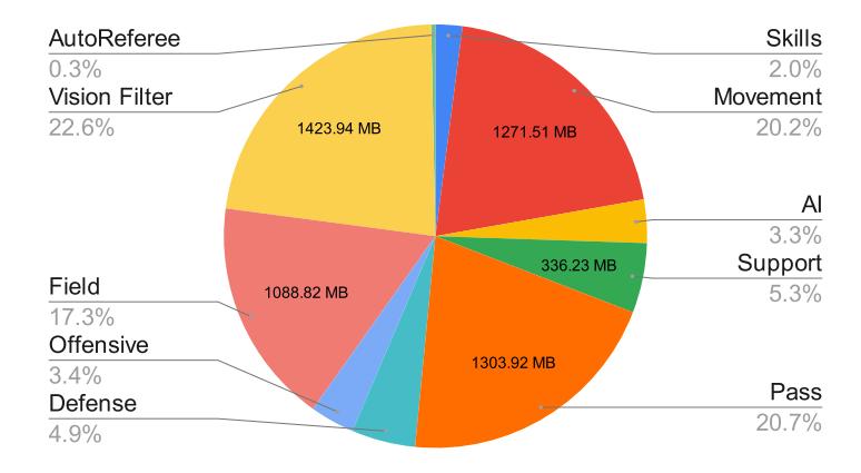
The memory footprint is similarly large, so the heap size should be set accordingly. The average heap usage is around 2 GB, but we set the maximum heap size to 12 GB during a competition to make sure the application does not run out of memory, which would be catastrophic. Figure 4 gives an exemplary overview of the sizes of the shapes in a replay that are stored for one half time.
The advantages of the object database come with the integration. It is as easy as adding an annotation to a data class and add the object to the current frame. Over the years, though, we decided to mainly persist the aforementioned shapes (see 2.2) and only add custom classes if reasonable. Previously, we persisted the whole AI state. While this usually worked fine there were several occurrences where someone accidentally added too much data into the AI state, which eventually caused the whole software to crash due to insufficient memory. This can still happen with the shapes, but developers are usually more conservative with adding shapes, than with creating internal states. Currently, shapes make up around 60% of a recording, AI data 25%, and the rest is world state information.
Another feature of the object database is, that changes to the classes are usually no problem. Some changes require no action, while others just need a mutation definition to transform older objects to the latest schema. In theory, one could support every past database, but we found that recordings are usually only interesting for a very short amount of time, because they get out-dated after changing the AI again. We usually delete them after a tournament. Nevertheless, it is still useful to have the compatibility feature for small changes to the data schema.
Usage Databases can be opened in a separate replay window which includes all the UI views that support replays, like the visualizer with the field, the log view, and robot information view. Shapes are displayed in the visualizer like described above in the normal view.
The data is stored frame by frame and with a timestamp as the primary key. This makes it efficient to seek through the database, because not all intermediate frames have to be loaded. Only those which are closest to the current timestamp. This is important when searching for certain situations by quickly seeking through the log. There are also some convenience search functions, like seeking forward to the next referee command or autoRef game event.
Sometimes it is useful to see if a certain situation is reproducible or how the AI behaves after recent changes. There are two ways build-in to achieve this. The AI can be run on the currently replayed frame. The AI will produce shapes that are added to the visualizer in addition to the original shapes. This makes it easier to compare the decisions. Nevertheless, it only works on behavior which has no complex state which is build up over multiple frames. Furthermore, robots obviously do not react to what the AI decides. For that, we have another tool: The current robot states and ball state can be copied as a snapshot to the clipboard. It is a simple JSON structure that can either be pasted into the simulation in the main window, or pasted into the issue tracker for other developers.
The recordings in the database do not include the raw SSL-Vision data. However, to analyze issues with the vision filter, we need the raw data. Therefore, we also have a recorder that saves standard SSL game logs.
2.4 Integration Tests
A lot of the low level math code can easily be unit tested, but the higher level AI code is much more complex and interconnected. Therefore, we developed a small integration test tool set that makes it easy to write tests that run the whole AI. There are two types of integration tests: One that includes the simulator and one that does not.
The simulation can easily be used in integration tests without having additional network connections in between. It can also be run at max speed, which reduces the overall duration of the tests significantly. Furthermore, every test is recorded during its execution (see section 2.3). If the test fails the recordings are published, otherwise the recorded data is removed. This is very useful to quickly figure out why the test failed.
Creating new integration test must be easy or otherwise developers tend to not implement as much tests. In our case creating a new integration test is very easy. The developer can launch Sumatra and move robots and the ball to the desired positions. After that a snapshot of the current game situation can be exported to the file system. The snapshot can then be used as initial situation for the integration test.
One implemented test case may look like in algorithm 1. To make sure that we can score on an empty goal from a kickoff, we first load a snapshot of a predefined constellation of robots and ball (where there are no opponents) and send a prepare kickoff command. The test then starts the simulation and waits with a certain timeout until the game state switches to running (i.e. the ball moved). If the game state is not running, the test failed. Otherwise, we simulate for another two seconds or until the ball left the field. If there is no possible goal game event, the test fails. Additionally, it checks if there were any warnings or errors logged and if there were other avoidable violations reported by the game-controller.
The tests are integrated in our CI system (Gitlab CI). In case a test fails the build pipeline fails and automatically uploads a recording of the failing test. The recording can be downloaded and viewed to figure out why the test failed very quickly.
Rule Tests
We implemented various tests to increase our stability and to ensure that our robots always comply with the rule book. Table 3 shows a list of some of the integration tests that are supposed to test the AI's behavior during various game states and game situations.
Table 3: Rule based test cases
| Test name | Test Criteria |
|---|---|
| testForceStartWithoutOpponents | Bots start moving and score a goal within 10s |
| testKickoff | GameState switches to RUNNING and bots move within 11s |
| testPenalty | Bots start moving and GameState switches to either HALT (GOAL) or BALL PLACEMENT (failed penalty) after 30s |
| testForceStart | Ball moves away from its starting position |
| testPathPlanning | Bot reaches destination in given time |
| testStopBall | Bot speed not exceeding max stop speed, bots move, not moving to close to forbidden areas during STOP |
| testBallPlacement | Bots move, GameState switches to PLACEMENT SUCCEEDED and then STOP |
| testKickoffWithoutOpponents | Bots start moving and score a goal within 11s |
| testFreeKickOpponentCorner | GameState switches to RUNNING and bots move within 6s |
Besides the actual test criteria all tests check that no errors or warnings are logged in the logging system. There is also a smoke test, which will simply run a simulated game between two of our own AI's (including AutoRef). The test checks if any exceptions, warnings or errors are thrown. Rigorous testing helps to increase the stability and correctness of our software framework and our AI.
Strategy Tests
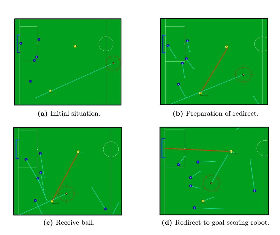
In addition to our rule based tests we also implemented tests that are testing specific strategy decisions that our AI makes during a game. Figure 5 shows an integration test of a typical game situation in front of the opponents goal with two attacking robots during RUNNING state.
Initially, the ball has been passed from our half to one of our attacking robots near the opponent goal (Fig. 5a). Afterwards, the attacking robot prepares to pass the ball to a second attacking robot (Fig. 5b). When the ball almost reached our first attacking robot, the second robot is preparing to receive the planned pass (Fig. 5c). After the ball has been redirected from the first to the second robot, the second robot is now planning to redirect the ball directly to the opponent goal (Fig. 5d). The test case tests if the first robot correctly receives the pass and redirects it to the other robot. Another criteria is that the second robot plans to score a goal after the first robot has redirect the ball.
We have implemented several test cases like the one shown in Figure 5 regarding passing and other offensive situations. Further test cases also test the interception of fast moving balls, correct role assignment of robots, robot one versus one behavior, goal shots in various scenarios and ball placement.
3 Offensive Dribbling
Our AI distinguishes between defensive and offensive dribbling. Defensive dribbling is concerned with getting the ball and protecting it from the opponent robots while always adhering to the dribbling rule constraints. Our attacking robot will remain in the defensive dribbling state until a good enough offensive strategy has been found (see section 2 in our 2018 TDP [4]). One of the strategies that the robot may choose is the so called FinisherMove, which is one of the offensive dribbling actions the robot can do.
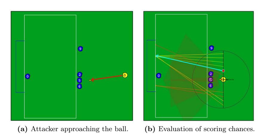
Figure 6 shows a typical scenario of a ball located in front of the opponent goal (Fig. 6a). In this case the robot chooses to do a FinisherMove. The robot checks if it is possible to score a goal from another position on a parallel line to the goal line near the dribbling starting position. Multiple points on the line will be sampled and evaluated for their chance to score a goal (green = high chance to score, red = low chance to score). The robot will choose the closest point that is good enough to score a goal (Fig. 6b).
The entire sample-line can move closer or further away from the opponent goal, depending on the behavior of the defending robots. This means that the sample-line is not always on the same location with the robot. In general the robot will try to avoid coming to close to opponent robots. The circle around the attacking robot indicates the maximum allowed dribbling distances and its center is the position where the robot started the dribbling process, no positions are sampled outside the circle to avoid dribbling rule violations.
The calculations are done on every AI frame. Meaning that there is no plan that the robot follows. Each frame the destination or the kick target can change. This is important, because we need to react fast to the opponents movement and re-evaluate our strategy constantly. If no more reasonably good chance to score is available anymore (or any other offensive action, e.g. passing), then the attacking robot will switch to the defensive dribbling mode. In this mode the robot will try to always stay between the closest opponent robot and the ball. The robot will stay in the defensive dribbling mode until a good offensive action is available again.
In all RoboCups prior to 2021 we mostly relied on pass and redirect plays to score goals. The addition of the FinisherMoves played a crucial role in winning the 2021 RoboCup. Not only do the FinisherMoves have the benefit of scoring goals directly, but they also make each robot in front of the opponents goal much more dangerous. Forcing the opponent team to use more defensive robots to cover the attacking robot handling the ball, making free the way for good passing and redirect opportunities.
4 Publication
Our team publishes all their resources, including software, electronics/schematics and mechanical drawings, after each RoboCup. They can be found on our website⁷. The website also contains several publications with reference to the RoboCup, though some are only available in German.
References
- A. Ryll and S. Jut. TIGERs Mannheim - Extended Team Description for RoboCup 2020, 2020.
- A. Ryll, N. Ommer, and M. Geiger. RoboCup 2021 SSL ChampionTIGERs Mannheim - A Decade of Open-SourceRobot Evolution. In R. Alami, J. Biswas, M. Cakmak, and O. Obst, editors, RoboCup 2021: Robot World Cup XXIV, 2022.
- Z. Huang, L. Chen, J. Li, Y. Wang, Z. Chen, L. Wen, J. Gu, P. Hu, and R. Xiong. ZJUNlict Extended Team Description Paper forRoboCup 2019, 2019.
- A. Ryll, M. Geiger, C. Carstensen, and N. Ommer. TIGERs Mannheim - Extended Team Description for RoboCup 2018, 2018.
- iC-Haus GmbH. iC-PX Series, 2016. https://www.ichaus.de/PX_datasheet_en.
- STmicroelectronics. STM32H743xI Datasheet, July 2018. https://www.st.com/resource/en/datasheet/stm32h743bi.pdf.
- Semtech Corporation. SX1280 Datasheet, May 2017. http://www.semtech.com/images/datasheet/sx1280_81.pdf.
- Monajjemi, Valiallah (Mani), Ali Koochakzadeh, and Saeed Shiry Ghidary. grSim - RoboCup Small Size Robot Soccer Simulator, 2011. Robot Soccer World Cup, pp. 450-460. Springer Berlin Heidelberg.
- A. Ryll, N. Ommer, D. Andres, D. Klostermann, S. Nickel, and F. Pistorius. TIGERS Mannheim - Team Description for RoboCup 2013, 2013.