Triton RCSC 2022 Team Description Paper
Hector Montenegro, Rafaella Gomes, Anika Bhattacharya, Chaowen Ma, Snir Kinog, Eric Wang, Victor Ku, Aditya Athota, Joaquin Caso, Yang-Jie Qin, Duy Pham
University of California, San Diego, Institute of Electrical and Electronics Engineers
Abstract This paper describes the design techniques and methodologies used to build autonomous robots meant to compete in the 2022 RoboCup Small Size League (SSL) tournament in Bangkok, Thailand. The robots have capabilities of path-finding, omni-directional movement, and high instantaneous power flow for kicking.
1 Introduction
The 2021-2022 season is the team's second attempt at the international competition. The COVID-19 pandemic led to several setbacks during the design and development stages including the loss of a project space and members returning to their home cities as the University of California implemented remote instruction. Current work focuses on design as per the lack of teammates in San Diego. Safety measures set in early 2022 will hopefully minimize new variant cases and reopen our work-spaces, equipment rooms, and increase our budget.
2 Mechanical Design
2.1 Drive Train
The robot uses four omni-directional wheels oriented at 100 degrees [6] for the front and rear wheels. This angle inclination provides more room for the dribbler mechanism of the robot. The layers and mechanisms of the prototype including the chassis, will be printed out of PLA. The finalized robot will use carbon fiber material for its sturdiness and light weight.
Table 1: Robot Specification Table
| Robot Component | Details |
|---|---|
| Embedded Computer | Broadcom BCM2711 Cortex-A72 (ARM v8) 64-bit SoC @ 1.5GHz (Embedded in Raspberry Pi 4B) |
| Embedded Microcontroller | STM32F427IIH6 Cortex-M4 (ARM) 32-bit C @ 180 MHz (Embedded in DJI RoboMaster Development Board Type A [abbrev. as RM]) |
| IMU System (9DOF) | MPU6500 6DOF IMU (Embedded in RM), IST8310 3DOF Magnetometer (Embedded in RM) |
| On-Robot Camera | 8 Megapixel Pi Camera |
| Proximity Sensor | ST VL53L1X ToF (Not included in the current prototype, but will appear in a future upgrade to detect ball-holding status) |
| Communication | WiFi between standard home router and our PC |
| Main Motors | DJI M2006 Motor with built-in encoders, Max 500 rpm, Max 44W, 416rpm at 1 Nm, @24V |
| Gear Ratio | 3.33, wheel speed up to 1385.28 rpm |
| ESCs | DJI C610 32-bit FOC ESC (interfaced with CAN BUS), @24V, @Max 10A |
| Wheels | GTF 50mm Omni Wheel |
| Dribbler Motor & ESC | T-MOTOR MT2212-13 980KV Brushless Motor (current prototype), XING-E 2207 1800KV Brushless Motor (future upgrade), ICQUANZX ESC BLHeli S 6s 35A |
| Kicker Circuit | LT3751 Capacitor Charger Controller IC, GA3459-BL Flyback Transformer (turn ratio 1:10), FDS2582 NMOS, ES3J, IKB40N65ES5, SMBJ13CA, 2700 Capacitor, LTC4231, LTC2955, @22.2v operating voltage, boost to 130V in 272 ms |
| Power Supply | Ovonic 1300mAh 22.2V 6S 100C |
2.2 Kicker
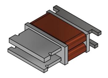
The team's previous traditional cylinder-shaped solenoid took up too much space (Figure 1). Therefore the TIGERs Mannheim's stadium-shaped solenoid design is used to maximize space efficiency [1]. The solenoid kicker contains five different components: the chassis, the solenoids, the plunger bar, the chip kicker and the front kicker (Figure 2).
The chassis is made of aluminum to ensure that the two solenoids are robust enough to endure the force from the plunger bar. The solenoid is wired with 22 AWG magnetic copper wire; it has about six to seven layers and more than 300 total turns of coils. High current passing through the solenoid attracts the plunger bar to the center and creates a force for the kicking mechanism. The plunger bar is made of ferromagnetic carbon steel to ensure the solenoid reacts to the medium. Its extended edge is attached to a spring to enable a retract mechanism for return to the original position.
2.3 Future Improvements
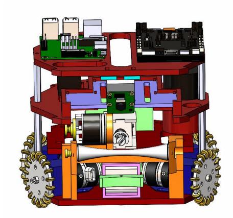
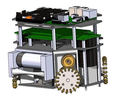
The team has taken the task of redesigning the robot's fundamentals in order to produce a more competitive robot looking into the 2022 competition. Though last season's design was operational, the team saw room for improvement (Figure 1). First, a gear ratio is to be included in order to match some of the SSL's more competitive teams (Figure 3). Second, an extra layer was added to provide ample space for the kicker PCBs. Third, the team is trying to follow its previously set goal of transitioning from pre-made components to manufactured. Though the design is a work in progress, the team anticipates its readiness for the competition.
3 Electronics
3.1 Kicker Board
The kicker board operates in two stages. The first stage of the power board is the battery protection circuit which shuts down power in case of reverse polarity, over-voltage, or under-voltage operation. The integrated circuit (IC) used to accomplish that task is the LTC4231 Micropower Hot Swap Controller. This chip is essential for safe insertion and removal of the battery in high power electronics. Additionally, the over-voltage/under-voltage protection circuits are built into this chip. The chip LTC2955 provides safe push-button operation and features a power kill input. In the second stage, the LT3751 High Voltage Capacitor Charger Controller allows for safe charging of the high capacity capacitor. The flyback topology connected to the chip charges the capacitor to a maximum of 500V. Once charged, the kicker circuit is driven by a FET connected to the capacitor branch [1].
3.2 Future Improvements Electronics
For the future, the team would like to aim towards designing our own motor controllers and micro-controller to replace the current DJI RoboMaster. With designing custom parts for our robots, we would be able to optimize the performance and efficiency of the overall system.
4 Embedded Systems
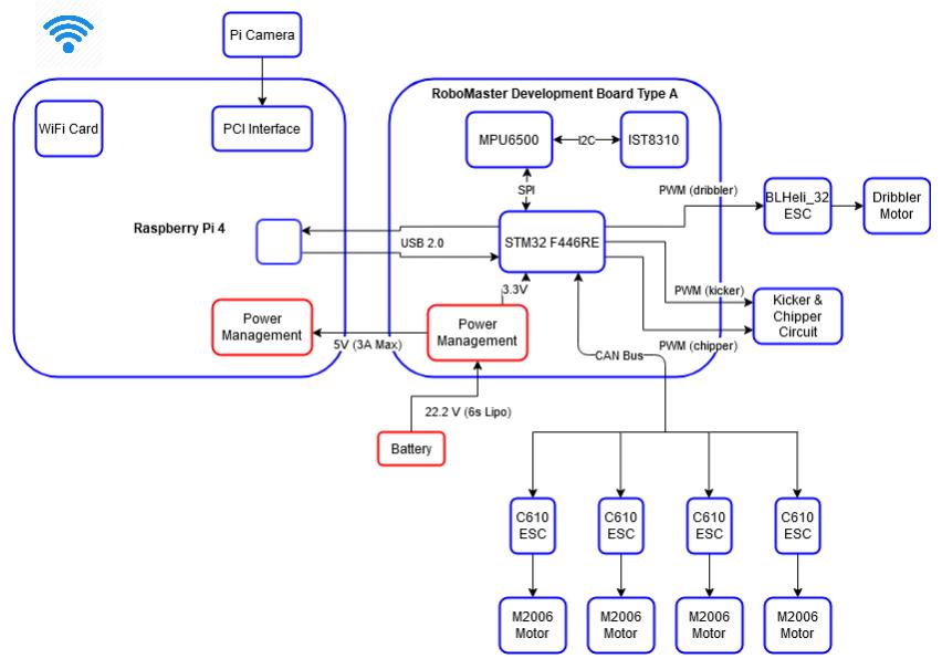
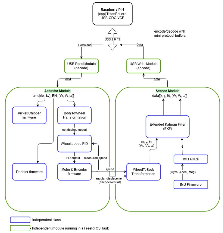
Embedded systems are responsible for the integration of hardware and software on the robots. Our goal is to establish a robust network of communication between the physical movers of the system, or actuators, and the software-coupled sensors to exchange data efficiently. Actuators perform specific tasks given a set of commands such as chipping, dribbling and kicking a ball. Each operation is predetermined by the algorithms' use of the sensor data. Universal Serial Bus (USB) is the preferred communication protocol because of its reliability and speed. FreeRTOS served the multitasking needs with its priority assignments to threads [2]. FreeRTOS in our application provides heap management, message queues, and multitasking on a STM32 microcontroller, which is programmed with the STM32 Hardware Abstraction Library (HAL). A Raspberry Pi 4 serves as the team's main source of computational power and will process the robot's vision via a camera.
4.1 Actuator Control System
The control system manipulates variables such as velocity, acceleration, and rotation to operate in a stable manner. The body-to-wheel transformation described by RoboTeam Twente is used to calculate the rpm of each wheel given the desired translational and rotational velocities [3]. The Proportional–Integral–Derivative (PID) algorithm controls wheel speeds.
The kicker and chipper circuits use constants representing the intensity of the kicks, kx and ky, to characterize the horizontal kick and the vertical chip, respectively. Kick intensities are functions of the voltage applied i.e., they are modified with a change of the PWM duty cycle sent to the Boost Converters. The dribbler works similarly, but instead of intensity parameters, it simply receives an enable signal to turn it on or off.
4.2 Synthesis of Data Using Sensors
The Inertial Measurement Unit (IMU) embedded inside the RoboMaster board has nine degrees-of-freedom (DOF); it integrates a gyroscope, accelerometer, and magnetometer. The AHRS (Attitude and Heading Reference System) Algorithm will fuse data collected from the three sensors to give the measurement of the current heading angle and acceleration state of our robot [5]. Although the ssl-vision data can also be used to infer the heading and acceleration, having an embedded IMU system supplies data with little latency and more accuracy.
The wheel-to-body transformation converts the angular velocity of each wheel into translational velocity of the entire robot [3]. In addition, we plan to implement an Extended Kalman Filter (EKF) algorithm to fuse the motion information from the encoders with the information inferred from the IMU system to give a more robust real-time motion estimation.
4.3 USB Integration of Actuators and Sensors
USB communication between the Raspberry Pi 4 and the RoboMaster board ensures high reliability due to differential signaling and fast speed that addresses the performance bottleneck of our distributed computing model. The team was particularly interested in the virtual COM port (VCP) application of the USB because of simplicity.
4.4 Future Goals
We would like to create a set of system specifications for the robot that translate to requirements for PID control. Percent overshoot, settling time, rising time, and maximum response to a unit disturbance all serve as effective design parameters that will improve performance if considered carefully. The PID control system needs better algorithms to deliver angular and translational velocities.
To more efficiently drive the EC45 motors, we are considering designing our own circuit using DC-to-DC power converters. A properly designed motor drive will allow for instantaneous changes in voltage, forward motoring, regenerative breaking, and higher efficiency.
The team is looking to replace Wi-Fi with radio communication to increase the speed of information transfer.
5 Software
5.1 General Setup
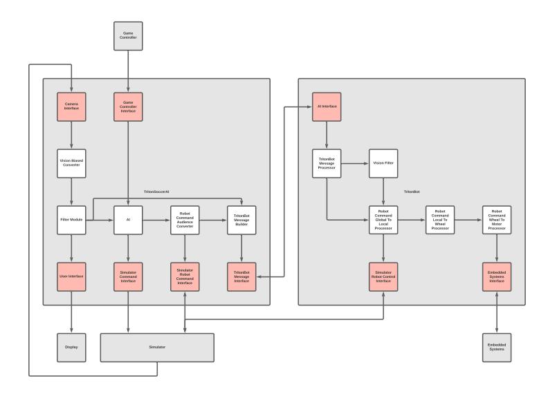
The general software setup is illustrated in Figure 6. Two programs were created: TritonSoccerAI and TritonBot. TritonSoccerAI is a Java application that is to be run on the central field computer. TritonBot is written in Python and is to be run on individual Raspberry Pis on each robot.
TritonSoccerAI is responsible for receiving and processing messages sent from SSL-Vision and SSL-Game-Controller. In the experimental setup, TritonSoccerAI receives vision information from the ER-Force Simulator. TritonSoccerAI coordinates each robot by sending robot-specific vision and robot-specific commands to TritonBot. These commands are from a global perspective. TritonBot receives these global commands, converts them into local, then wheel, then individual motor commands. In the competition setup, these motor commands will be sent to embedded systems through USB. In the experimental setup, local commands are sent to the simulator.
5.2 Shared Modular Architecture
Inspired by the inter-process Publisher-Subscriber system in ROS (Robot Operating System), both programs use a simplified Publisher-Subscriber system for convenient inter-thread communications [7]. Each module consumes and publishes to exchanges facilitated via RabbitMQ.
Both programs are modular. Each module operates on a separate thread. Each module communicates with other modules by sending messages sent through labeled exchanges and facilitated by RabbitMQ. Protocol Buffers are used for data serialization. Modules are decoupled, with each module only being aware of their own incoming and outgoing exchanges. Modules are organized into two categories: interface modules and processing modules. Interface modules receive and send information outside of the application. Messages received from outside or sent outside do not use a publisher subscriber system. Processing modules operate completely within the application and all communication of processing modules uses the publisher-subscriber system.
While the majority of modules shown in Figure 6 are already roughly implemented, modules for interfacing with SSL-Game-Controller and modules that further process local commands are not yet implemented.
5.3 TritonSoccerAI Software (Java)
TritonSoccerAI runs on the central field computer. It is responsible for receiving vision and game state information and sending messages to update and command individual TritonBots.
Vision information is processed into messages sent to TritonBots via the following process. First, the Camera Interface receives vision information either from SSL-Vision in a tournament setup or from the ER-Force Simulator in our experimental setup. The wrapper packet is sent to the Vision Biased Converter to be converted into a biased perspective (vertical field with the team goal placed below and the opposing team's goal placed above). This biased wrapper packet is sent to the Filter Module where it is converted into a filtered wrapper packet that processes the biased wrapper packet and adds additional metadata about objects such as velocity, acceleration, and dribble ball contact state. The AI Module receives the filtered data and converts it to individual robot commands to be sent to each robot. The command is still from the biased perspective of a team and must be further processed into an unbiased "audience" perspective by the Robot Command Audience Converter. The TritonBot Message Builder receives both the processed robot command and the unprocessed wrapper packet to create a single TritonBotMessage to be sent to each TritonBot via the TritonBot Message Interface.
TritonBot Software (Python) TritonBot is a python program that runs on the Raspberry Pi 4 SBC (Single Board Computer) of every robot. It functions as an intermediary between TritonSoccerAI and the low-level embedded systems by recieving robot commands and vision data sent from TritonSoccerAI and performing the necessary format conversions and control algorithms. First, the AI interface recieves a wrapper packet containing the commands sent by TritonSoccerAI as well as vision data for the respective robot via UDP. The AI interface then relays the wrapper packet to the TritonBot Message Processor which splits the packet into vision data that is sent through a filter module first to reduce noise and the commands which is given from the global reference frame of the field. The vision data and commands are then relayed to a module which processes them and converts the global command to a local command from the reference frame of the robot. These local commands either be sent to the simulator via the simulator interface modules or to the motor controllers through a series of transformations from local commands, to individual wheel commands, to the motor control algorithms. Feedback received from any sensors on the robot in competition or from the simulator in an experimental setting will be routed through the embedded systems interface or the simulator interface respectively and relayed back to the AI Interface, where it will be sent back to TritonSoccerAI.
5.4 Algorithms
Path Finding Algorithm
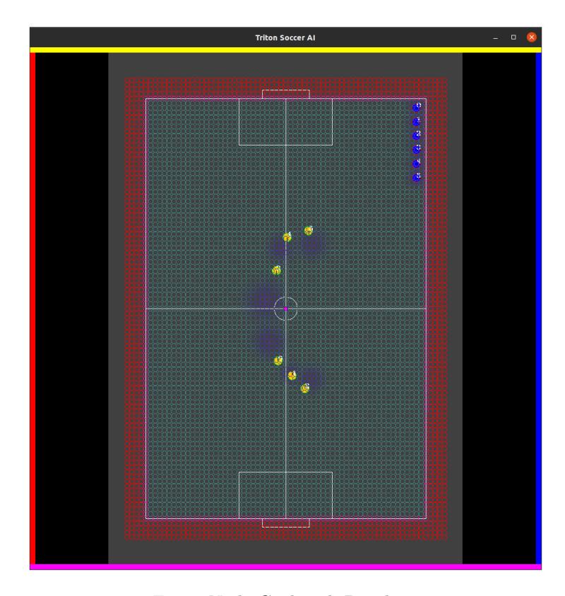
This subsection explains the design of a path finding algorithm. The pathfinding framework is currently built based on the A* search algorithm, which is a fast way to find the shortest path given the nodes of the field and its list of neighbor nodes. The field, as shown in Figure 7, is represented by a grid of nodes so the A* algorithm returns the list of nodes connecting two points which serves as the fastest path through the nodes.
A* search can be described as an extension to Dijkstra's algorithm. The key to this algorithm is the heuristic computed for each node. The heuristic is a quick way to estimate how good the path towards each node is expected to be. This allows it to always make the least-costly decision and dramatically reduce the amount of neighboring nodes it checks.
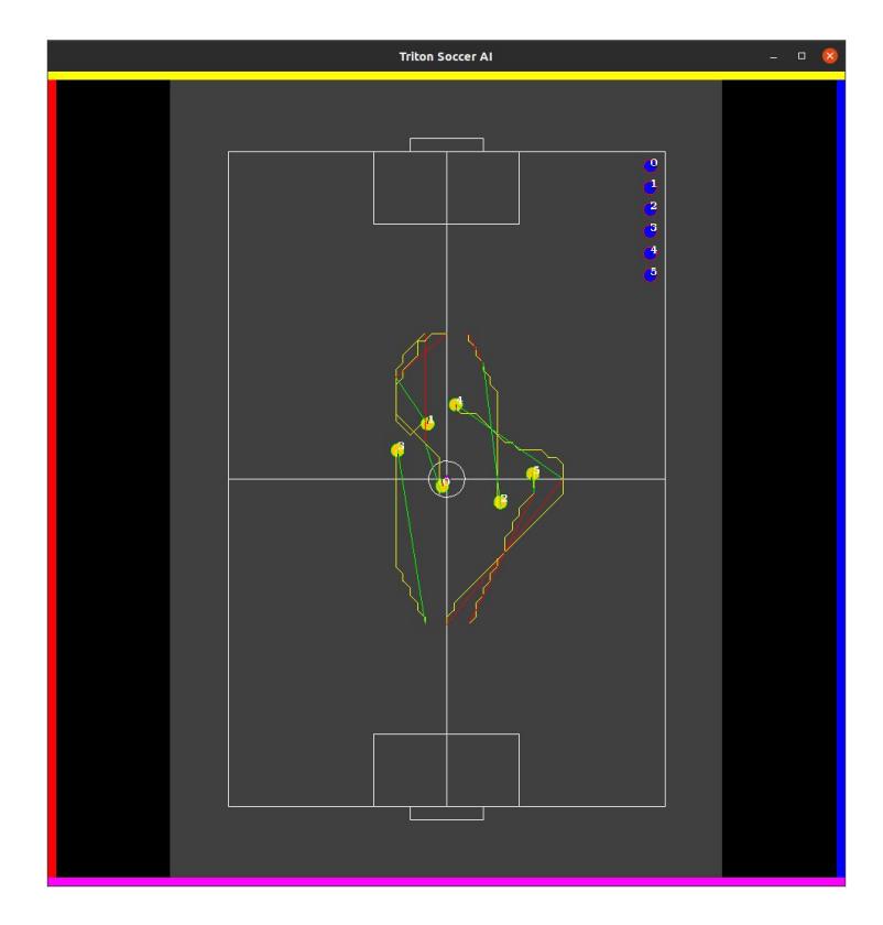
One limitation with the pure A* algorithm is that it can only move to different grid nodes at 45 degree intervals, thus limiting it to 8 directions (4 cardinals and diagonals). We further optimized the discrete grid paths produced by A* with any-angle path planning, which is demonstrated in Figure 8. This checks the furthest returned path vertices in its line-of-sight to the target to see if directly moving to another vertex would have a lower score, which is calculated using our heuristic. The heuristic involves a penalty that's found from the obstacle value of the node nearest to a point. You start from the farthest node and work back in the path towards your current location until you can find a clear-line-of-sight to ensure you can move as far down the path as possible and as quick as possible. This allows for the robot to move at any angle and maximizes the efficiency in the path it takes. The precision is not as imperative because things will constantly be moving; The goal is simply to find a general direction to move towards until the route is recomputed a short time later.
Endpoint-In-Obstacle Handling
We set the dynamic obstacles(other robots)' radius to be much larger than the actual robot radius to maintain a safe distance to other robots. It means when a robot accidentally gets too close to another robot, the beginning of the path may be in the obstacle. This is handled in our post-pathfinding optimization where we try to find the most efficient next travel node. This is done by trying to find the farthest node (in the path we found with A*) that has a clear line of sight (i.e. a straight path with a lower penalty than the start position). If the target is inside of an obstacle, the robot will move towards the target but won't travel into a node with a higher penalty than it's current position.
Robot and Ball Predictions
We have a rather simple implementation to predict the location of the robot and ball. We take the current position of the objects and scale them by their velocity components and the time difference to produce a space where the robot and ball could be predicted to end up.
5.5 Skill System
Currently, the AI runs what we call a 'Skill System.' Each skill is composed of other skills, which may also be composed of other skills, etc. There are team skills (Attack and Defend), individual skills (e.g. ChaseBall, GoalShoot, etc.), coordinated skills (e.g. Pass), and basic skills (Dribble, Kick, and MatchVelocity). The sub-skills of a given skill must finish execution in order to for the higher level skill to finish execution. Multiple skills can run concurrently.
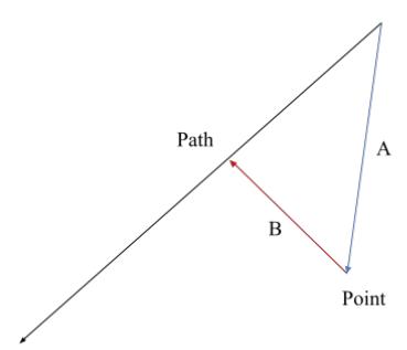
General Algorithm: Smallest Distance From Path to Point
The AI uses vector rejection to determine the smallest distance from path to point. As shown in the figure above, the vector from the start of the path to the point (vector A) is rejected onto the Path, resulting in vector B. Vector B is equal to vector A times the cosine of the angle between the Path and vector A.
Skill: CatchBall
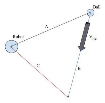
When a robot is in position to catch a ball, the CatchBall skill determines the shortest possible distance the robot has to travel to catch the ball, based on the velocity vector of the ball, position of the ball, and the position of the robot. As shown in the figure above, CatchBall subtracts the position of the robot from the position of the ball to determine the vector from the ball to the robot (A). CatchBall then projects that vector onto the velocity vector of the ball (B). Finally, CatchBall subtracts vector A from vector B to get vector C, the path the robot should take.
Skill: GoalShoot
When a robot is in position to attempt a goal, the GoalShoot skill determines the best possible shot based on the position of the robot in relation to the goal and the positions of nearby obstacles (other robots, friend or foe). GoalShoot sets up a grid of possible locations the robot can shoot from, sets up a line of possible shots on the goal, and calculates the vectors from each point on the grid to each point on the line. These are the potential shots the robot can make. GoalShoot then calculates the distance from nearby obstacles to each possible shot using Smallest Distance From Path to Point. Based on how far the robot will have to move to get into position and how close the possible shot is to obstacles, GoalShoot determines the optimal shot.
Skill: Pass
When a robot is in position to make a pass, the Pass skill determines the best possible pass based on the position of the robot making the pass, the position of the robot receiving the pass, and the positions of nearby obstacles. Like GoalShoot, Pass sets up a grid of possible locations from which the sending robot can make the pass. It then calculates the vectors from each point on the grid to the robot that will be receiving the pass (possible passes). Pass then calculates the distance from nearby obstacles to each possible pass. Based on how far the robot will have to move to get in position and how close the possible pass is to obstacles, Pass determines the optimal Pass.
Pass only takes into account obstacles in front of the robot making the pass, those for whom the dot product of the unit vector from robot to obstacle and the vector from robot passing to robot receiving are positive.
5.6 Future Goals
Future Modules Before actual competition, both TritonSoccerAI and TritonBot need additional modules. TritonSoccerAI requires a module to receive SSL-Game-Controller messages. TritonBot needs modules to process local commands to wheel commands, wheel commands to motor commands, and a module to send these motor commands to the embedded system. The future AI will also require additional modules to generate probability maps.
Future Pathfinding Improvements The current pathfinding algorithm functions well for simpler situation but needs improvement in finding the most optimal path. In the Robocup competition, there will often be scenarios where the path to the target location is completely free from obstacles. This knowledge can be used to design a more efficient pathfinding algorithm. In the past, we have integrated Jump Point Search (JPS) in our pathfinding, which has yielded very optimal results, and we hope to do so again this year.
JPS is an optimal algorithm for finding a path when there are few obstacles [4]. This algorithm aims to jump-ahead in a particular direction as far as possible, thereby skipping many nodes. The goal is to expand until you reach a node of interest, which could be a things such as a "forced neighbor" (e.g. an obstacle nearby that breaks the assumption that heading further in that direction is most optimal), an edge, or the target node. That node is then added to the open set and then the scenario is re-evaluated. Just like with A*, the paths generated from JPS can be post-smoothed by checking line-of-sight with the other nodes further down in the path.
Additionally, the prediction of the field is rather simple at the moment. The obstacles are currently approximated with circle, which a more precise and accurate representation would be elliptical objects since they likely would be moving. The shape of the ellipse can be determined by its velocity. In addition, the accelerations of the objects have not been accounted for yet due to all the noise. The accuracy of both the velocity and acceleration can be increased by implementing noise filtering. This will be especially important when integrating the Triton Bots in real life since there will certainly be a great deal of noise.
Future AI Improvements The current skill-based system of the AI is too slow. Though some skills terminate quickly, others may take take longer to run, which can hold back the AI from making decisions with regards to skills that have already terminated. We are considering developing a Finite-State Machine (FSM), Behavior Tree, or implementing Goal Oriented Action Planning (GOAP).
In a FSM, the AI is composed of one or more states, and only one state can be active at any given time. Our AI could have preset tactics as states and transition between them depending on the progress of the game.
A Behavior Tree uses a tree data structure, whose nodes are simple tasks. The AI determines which tasks to perform based on the progress of the game.
A GOAP is made up of multiple modular actions. The AI determines which sequence of actions at what frequencies will achieve its goal most efficiently. Given a situation, our AI would determine the best course of action.
Currently, our design relies heavily on the ssl-vision data provided by the field central camera. The ssl-vision data are susceptible to wireless communication latency and intrinsic noise. To deal with the latency, we plan to integrate a Pi Camera as both a ball detector and visual odometry. Furthermore, we plan to include an EKF algorithm mentioned in our system design to handle the noise.
6 Acknowledgements
We would not have been able to make so much progress without the RoboCup community for the extensive information put online in terms of EDTP, TDPs and GitHub repositories. We would also like to thank TIGERS Mannheim, for their extensive contributions to the RoboCup community and being advocates of open source development. Finally, a big thanks to Nicolai Ommer for his responsiveness and lending of the field camera.
We would also like to thank the UC San Diego IEEE Chapter for their support, guidance, and funding.
A special thanks is due to Professor Amy Eguchi with helping us establish contact with the RoboCup organization and helping the team grow its connections.
References
- Andre Ryll, S.J.: Tigers mannheim (2020)
- Barry, R., et al.: Freertos. Internet, Oct (2008)
- Bos, L., Citgez, Y., Dorenbos, H., Eichler, A., et al.: Roboteam twente extended team description paper 2020. RoboCup Wiki as Extended Team Description of RoboTeam Twente Team (2020)
- Harabor, D., Grastien, A.: Online graph pruning for pathfinding on grid maps. In: Proceedings of the AAAI Conference on Artificial Intelligence. vol. 25 (2011)
- Mahony, R., Hamel, T., Pflimlin, J.M.: Nonlinear complementary filters on the special orthogonal group. IEEE Transactions on automatic control 53(5), 1203–1218 (2008)
- Ryll, A., Ommer, N., Geiger, M., Jauer, M., Theis, J.: Tigers mannheim (2019)
- Stanford Artificial Intelligence Laboratory et al.: Robotic operating system, https://www.ros.org