2022 Team Description Paper: UBC Thunderbots
Amr Almoallim, Chantal Sousa, Dannon Sturn, David Antoniuk, Francesca Crema, Henry Bryant, Jonathan Lew, Jordan Liu, Kenny Wakaba, Liam Bontkes, Yichen Zhou
Department of Computer Science, The University of British Columbia; Department of Electrical and Computer Engineering, The University of British Columbia; Department of Engineering Physics, The University of British Columbia; Department of Integrated Engineering, The University of British Columbia; Department of Mechanical Engineering, The University of British Columbia
www.ubcthunderbots.ca · https://github.com/UBC-Thunderbots/Software
Abstract This paper details the design improvements the UBC Thunderbots have made in preparation for Robocup 2022 in Bangkok, Thailand. The primary focus was to physically build a new fleet of robots based on the design proposed in the 2020 TDP with a revised electrical system from 2021-22. The secondary goal was to improve the software AI architecture and game-play testing.
1 Introduction
UBC Thunderbots is an interdisciplinary team of undergraduate students at the University of British Columbia. Established in 2006, it pursued its first competitive initiative within the Small Size League at RoboCup 2009. The team has consecutively competed in RoboCup from 2009 to 2021 and is currently seeking qualification for RoboCup 2022. Over the years, the team has made significant developments of its team of autonomous soccer-playing robots. This paper will outline the progress made in continuing the development of the 2020 robot design, as well as a new electrical design and subsequent modifications in order for the team to compete with a new fleet of robots for Robocup 2022.
2 Mechanical
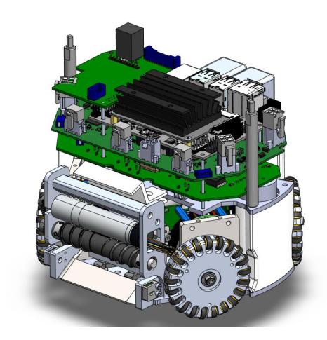
The subsequent section outlines mechanical changes made to our dribbler and chipper systems over the past year. The remainder of our robot remains unchanged mechanically since we are satisfied with their performance compared to our 2019 models.
2.1 Dribbler
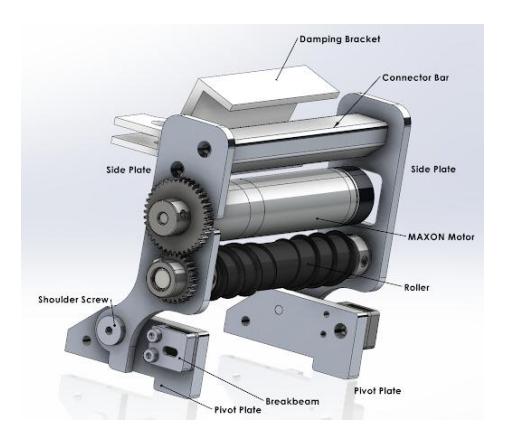
We have improved our dribbler's design by including several cutouts for ease of assembly and maintenance. Figure 2.2 outlines the dribbler components. The side plates received additional cutouts to accommodate the ECXSP16L BL KL A HP 24V Maxon dribbler motors we now use, which are longer than its predecessor and require additional space for its wires. A cutout was added near the pivot plate to accommodate the breakbeam's new position which was higher than previous designs. Extra material was removed from the pivot plates near the breakbeam to create more space for wire management. Lastly, a cutout on the left side plate was added so that the motor axle could easily be slid in and out during assembly and maintenance.
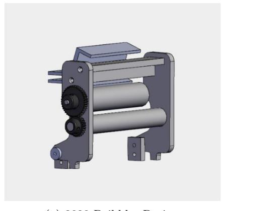
Figure 2.3 shows that our dribbler shares a pivot plate with the chipper for the sake of spatial efficiency.
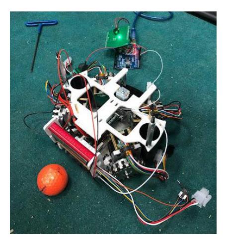
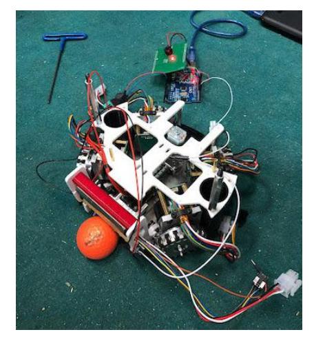
The position of the breakbeam has been changed; an Arduino infrared sensor was used to test the function and reliability of the breakbeam. Figure 2.4 shows the breakbeam being successfully triggered, as the LED changes colour from green to red.
2.2 Chipper
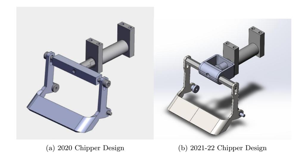
Through hardware testing, the team has discovered that the proposed chipper from the 2020 design was too weak to be effective. We hypothesize that it was due to the fact that the solenoid's acceleration was damped by needing to fully pull the chipper arm from its starting to actuated position.
As shown in Figure 2.5 above, we replaced the straight square bar with standoffs and a U-bracket. In the new design, the ferromagnetic rod is tied to an end stop which would only actuate the chipper arm after a period of acceleration by the solenoid. The hope is that by accelerating to a higher speed first, the chipper arm would receive more momentum from the solenoid and thus generate a stronger chip than our original design.
3 Electrical
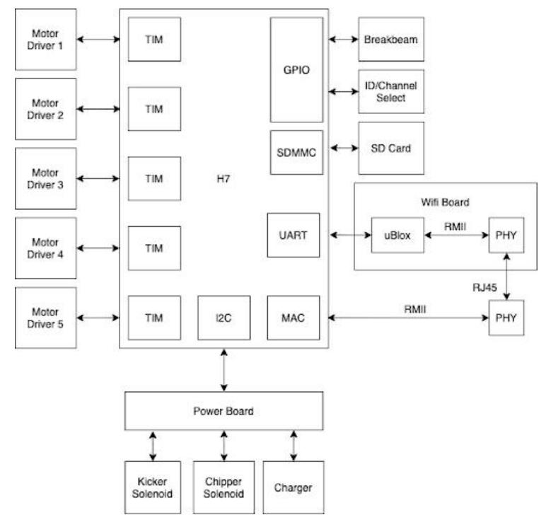
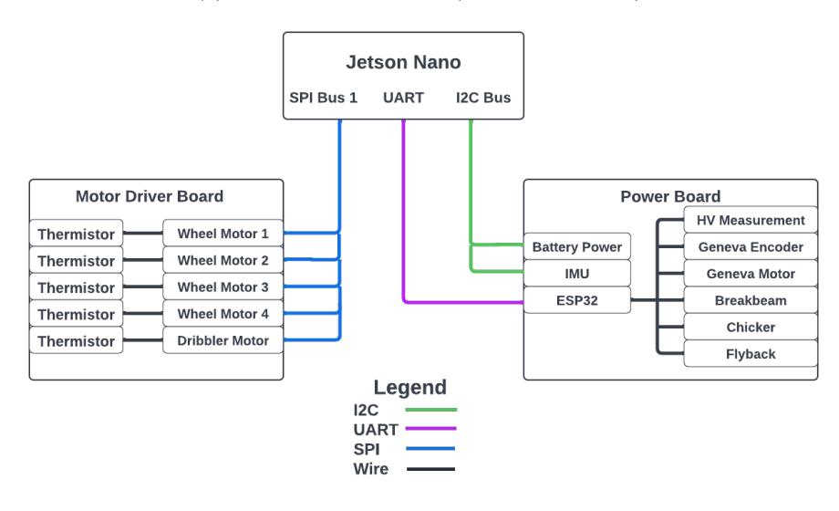
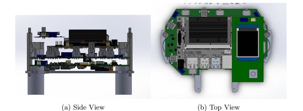
This year marks the second revision of our proposed electrical system from our 2020 TDP. Many of the changes we have implemented have been driven by needs from the software and mechanical subteams, including some quality of life improvements. In addition, we have also made improvements to our electrical system that can be modified and scaled up to future proof our robots. The most notable change from the 2020-2021 electrical system, which is shown in Figure 3.1a, is the removal of the STM32H7 microcontroller. At a high level, the issues with STM32H7 are due to overly complicated firmware and drivers, making continuous support very difficult. To resolve this, the electrical system has transitioned to using a Jetson Nano as the MCU. Additionally, we have made improvements and added new components to our Power, Motor Driver, and Encoder Boards, and created our first User Interface Board to allow easier access to robot parameters and diagnostics on the field. This is shown in Figure 3.1b.
3.1 Electrical System Overview
A key motivation for choosing the Jetson Nano is ease of development and deployment. First, the Jetson Nano supports Linux, which supports communication interfaces, e.g. SPI, UART, with semantics that many students are already familiar with. Second, the Jetson Nano supports plug-and-play Wi-Fi, which means that we can debug and deploy new software wirelessly (even remotely!), i.e. without a debugger cable. Finally, the Jetson Nano obviates the need for a Mainboard (the board we included in 2020-21 for the STM32H7). While additional information about the software architecture will be published in a future TDP, the design implications for the electrical systems are described in each of the sections below.
Electrical PCBs Overview
| Project Name | Functionality |
|---|---|
| Power Board v3.3 | Power generation and distribution for the robot, low-level |
| peripheral interfacing. | |
| Motor Driver Board v5 | Wheel and dribbler motor field-oriented control and feed |
| back. | |
| Encoder Boards v2.0 (x4) | Wheel motor position feedback. |
| UI Board v1.0 | Improved user interface functionality for robot variables |
| and parameters. |
3.2 Power Board
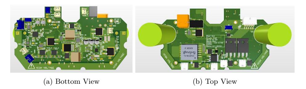
Our Power Board in 2020-21 was solely focused on power monitoring and generation for the robot. This year, the Power Board still delivers power to the robot, but as a result of replacing the STM32H7 with the Jetson Nano Development Board, we have had to move some of the robot functionality to the Power Board, such as kicker and chipper control as well as Geneva motor control.
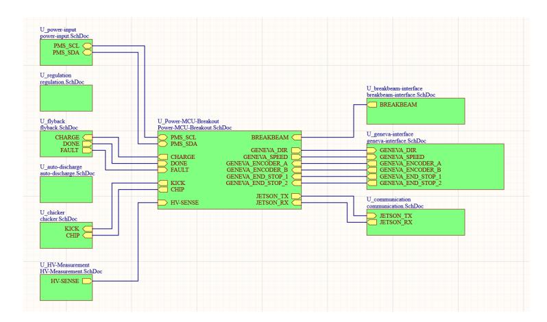
At a high level, the latest Power Board (V3.3) consists of the functional blocks as shown in Figure 3.3. There is an ESP32-PICO-D4 MCU at the center, which monitors power and controls high voltage charging, kicking, chipping, and the Geneva motor. It also monitors the breakbeam, performs high voltage sensing, and communicates with the Jetson Nano.
Power MCU: The Power Board MCU is an ESP32-PICO-D4. It is used to control high voltage charging, kicking/chipping, and the Geneva motor. It reads the breakbeam, high voltage measurement, and Geneva encoder outputs. It communicates with the Jetson Nano over UART.
Geneva Control: The Geneva motor is a new feature being added to the robot this year, which gives the robot the ability to make angled passes and kicks. With no dedicated mainboard this year, the control of the Geneva motor has been added to the Power Board.
PGND and GND Split: To isolate GND noise from the kicking/chipping solenoid actuation, we split our ground plane into a quiet GND and a noisy PGND, where the two planes are connected at a single point through a zero Ohm resistor.
3.3 Motor Driver Board
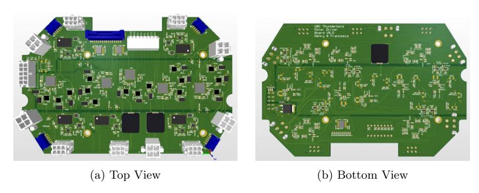
Our previous motor driver solution, the Allegro A3931, worked for basic control of our BLDC motors, however, due to stock issues and the fact that we want to implement FOC for more efficient and precise control of our motors, a new solution was required. Therefore, our new Motor Driver Board revision is designed around using the Trinamic Motion Controls TMC4671 controller and TMC6100 driver combination. Additionally, due to the inclusion of Jetson Nano computers in our robots, we wanted to take advantage of the SPI communication lines to reduce the amount of traces and pinouts needed. Finally, instead of 5 separate Motor Driver Boards per robot, which is what our 2020 design included, only 1 of these boards is needed per robot. This simplification is due to SPI signal integrity concerns from additional connectors and to reduce the complexity of the mechanical design.
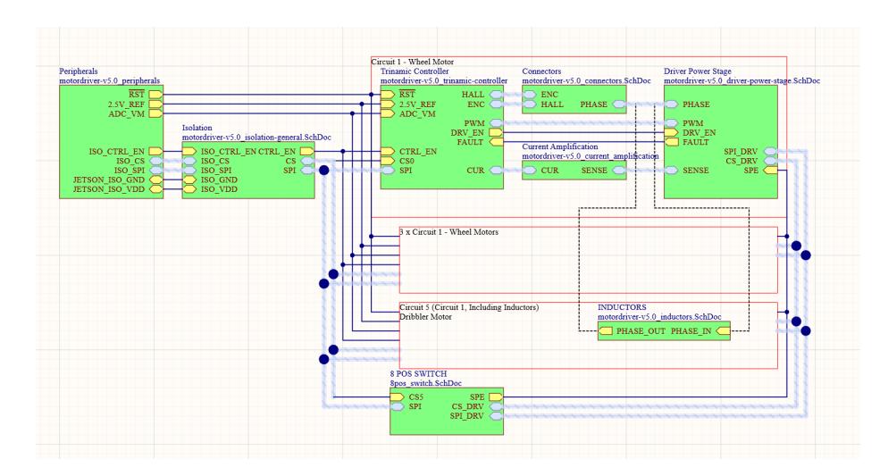
Figure 3.5 is a simplified visual description of the Motor Driver Board on a top level connection. We have simplified the connections using text boxes to show the additional motor circuits not pictured due to them being functionally the same as Circuit 1.
The controllers and drivers communicate via SPI to and from the Jetson Nano. The dribbler motor circuit includes inductors in series with its phases to reduce current spikes since it operates at a higher PWM frequency. These inductors also contribute to the longevity of the dribbler motors by preventing overheating during operation due to current spikes. The Motor Driver Board's design was heavily based on the schematics for the TMC4671+TMC6100 Breakout Board by Trinamic.
SPI/Hardware Configuration Select: Due to early testing challenges, we added physical switches to switch between hardware and SPI-set configurations on our first board revision. SPI configuration will be used for the final design.
Controller and Driver Circuit Considerations: In order to protect the drivers from voltage spikes from the BLDC motors, we included snubber filters and protection diodes. In our previous Motor Driver Board design, the Allegro A3931 contained internal current sense amplifiers to allow motor current readings. Since the TMC6100 does not include these, we used two TSC214ICT external bidirectional current sense amplifiers per motor circuit.
3.4 Encoder Board
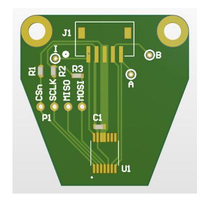
An Encoder Board is placed over each wheel BLDC motor to determine the wheel position. The previously designed Encoder Boards used differential analog signals using the TLE5009 magnetoresistive sensor. Unfortunately, the analog signals experienced a lot of interference which made the analog to digital conversion unreliable. To eliminate this issue, this year's Encoder Board converts the wheel position into a digital signal using the AS5047U sensor.
3.5 User Interface Board
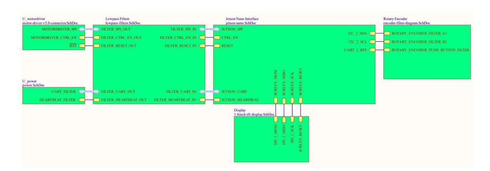
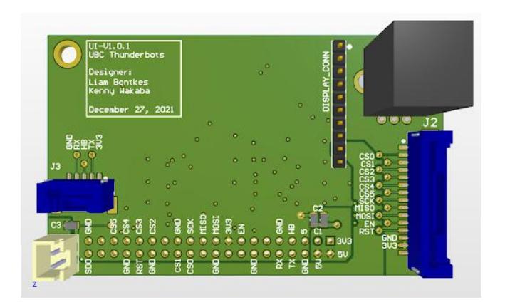
In previous years, our robots had piano switches for us to set Robot IDs, which was a tedious process when working with multiple robots. There was also was no convenient way to interact with robot variables. The User Interface Board (UI Board) simplifies access to and visualization of the robot parameters through a screen and a rotary switch. It also functions as a breakout board to filter signals coming in to and out of the Jetson Nano.
The UI Board consists of the functional blocks shown in Figure 3.8: the Motor Driver Board interface, the Jetson Nano interface, the TFT LCD display, the rotary encoder, and the Power Board interface.
4 Software
All software & firmware is open-source, and is available from our git repository: https://github.com/UBC-Thunderbots/Software.
4.1 Data Logging and Replay
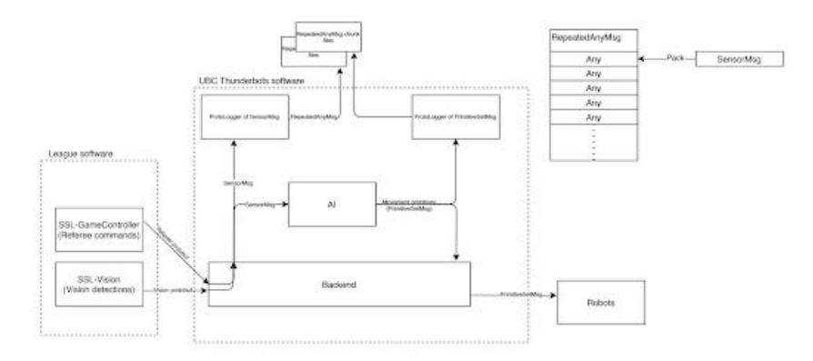
After RoboCup 2019, we removed ROS from our system. With this refactor, we lost the "rosbag" utility that previously gave us the ability to replay the input we received from SSL-Vision and examine the various outputs of our AI stack to debug difficult-to-reproduce issues. Taking advantage of the fact that our communications with Small Size League software and with our robots all use Google's Protocol Buffers (Protobuf) library for communication, we implemented a system that would log a series of Protobuf messages to files. The ProtoLogger component is capable of logging a series of Protobuf messages to chunk files containing multiple messages of the same type, which go into a directory containing other chunks with file names ordered by time. Because we log data in chunks instead of as a single, large file, we are capable of recovering most of the data leading up to a software crash.
In order to integrate this system, the sensor fusion component of our software had to be reworked to consume the "SensorMsg" message type, which is a oneof type of either SSL Vision, SSL Game Controller, or status messages from robots. This way, we can replay data of different types in the exact order that they initially arrived at our software.
4.2 Implementation of Hierarchical Finite State Machines in Tactics
As outlined in our 2016 TDP gameplay system, we implemented CMDragon's Skills, Tactics and Plays (STP) schema through Boost Coroutines. This allowed us to easily design procedural code for individual robot behaviour, but had limitations in its flexibility for managing conditional state transitions. Another limitation of the old architecture is that it explicitly used two layers of coroutines to represent an individual robot behaviour that did not work for all types of robot behaviour. This year, we introduced a hierarchical state machine framework called SML to manage the state machine logic. This framework allows us to easily write complex state transitions and at the same time inherit logic from other state machines to reduce duplication. A Tactic can have as many and as few layers of hierarchy as it requires. For example, a Move to Position Tactic can be implemented with a simple state machine, while an Intercept Ball Tactic's complexity necessitates more stages and sub FSMs.
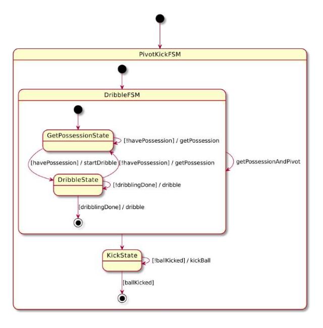
In Figure 4.2, we show a hierarchical FSM to represent pivoting and kicking the ball. The PivotKickFSM uses the DribbleFSM to get possession of the ball and then bring ball to kick origin. Only once the DribbleFSM is done bringing the ball to the correct location does the PivotKickFSM transition to the KickState and kick the ball. In the diagram, actions, shown following a slash ("/"), are performed on the transition between or within states to decide what low-level behaviour to perform on the robot. Guards, shown in square brackets ("[]") are the conditions that decide what transitions to make and are determined through evaluation functions on the state of the world. Notice the startDribble action when the DribbleFSM transitions to the DribbleState. This action triggers tracking of the total dribble distance to respect the 1 meter dribble limit that is part of the SSL rules. Once we lose possession of the ball and then gain possession of the ball to dribble again, we call startDribble to reset the tracking.
4.3 Simulated Testing
A major goal of the software team has been integrating simulated testing in our continuous integration system as well as playing games in simulation between two versions of our AI. To adapt a simulator for continuous integration, we need to ensure determinism. We do this by running a tick of our AI, a tick of our simulator, and validation functions in a loop. This ensures that the AI sees the same information every time the test is run and the simulator sees the same commands every time it is run. The validation functions check that the gameplay is working as intended. We have two types of validation functions: terminating and non-terminating. For a terminating validation function, there's a "failing until condition is true" semantic, so if the condition is always false, then the test will timeout and then fail, and if the condition becomes true, then the test immediately passes. For a non-terminating validation function, there's a "passing until condition is true" semantic, so if the condition is always false, then the test will timeout and then pass, and if the condition becomes true, then the test immediately fails. These two types of validation functions cover the semantic space we need for our simulated tests. The simulator is configured to invoke the same firmware that we use on our robots to send movement, kick, chip, and dribble commands to the simulator. We have two types of Simulated Tests: Simulated Tactic Tests and Simulated Play Tests. For Simulated Tactic Tests, we run a Tactic on an individual robot and check that the individual robot behaviour is as expected. For Simulated Play Tests, we run coordinated full team gameplay, and so we can check for high-level behaviour such as following rules and proper positioning to take shots or block enemy shots. Following the generous open-source contribution of a realistic simulator by Er-Force, we adapted the simulator into our simulated tests to allow us to test with more realistic simulated vision data and physics.
4.4 E-Stop
Emergency Stop (E-Stop) is a system responsible for bringing robots to an immediate stop in cases where the robots pose danger to themselves or their surroundings. The stop is initiated by a human user through a switch. Previously, E-stop was communicated through a dongle via radio. Since moving to WiFi, the handling of the E-stop switch had to be transferred to another component. This year, we use an Arduino Uno that interfaces with the switch to periodically receive the state of E-Stop. At the start of the program, we establish a UART connection between the backend and the Arduino. Whenever the switch is in the E-stop state, the backend blocks any primitives from being sent to the robot, replacing them with the special E-stop primitive. On the robot, the E-stop primitive prompts the robot to immediately stop and stabilize. We used Bazel Skylark rules to incorporate Arduino code building and flashing into our software environment.
5 Conclusion
We believe that the design changes detailed above will lead to significant improvements in performance. We look forward to putting the changes into action at RoboCup 2022.
6 Acknowledgements
We would like to thank our sponsors, as well as the University of British Columbia, specifically, the Faculty of Applied Science and departments of Mechanical Engineering, Engineering Physics, and Electrical and Computer Engineering. Without their continued support, developing our robots and competing at RoboCup would not be possible.
References
- P. Dumitru, G. Ellis, J. Fink, B. Hers, J. Lew, M. MacDougall, E. Morcom, S. H, C. Sousa, W. Van Dam, G. Whyte, L. Zhang, S. Zheng, and Y. Zhou, "2020 Team Description Paper: UBC Thunderbots," 2020.
- NVIDIA, "Jetson nano developer kit for ai and robotics," 2022.
- J. H. Bickford, "Geneva mechanisms," 1972.
- Trinamic Motion Control, "TMC4671+TMC6100 BOB Description Data Sheet," 2020.
- ROS, "Ros," 2022.
- R. De Iaco, S. Johnson, F. Kalla, L. Lu, M. MacDougall, K. Muthukuda, J. Petrie, M. Ragoonath, W. Su, V. Tang, T. Tsu, B. Wang, B. Whyte, C. Xie, K. Yu, E. Zhang, and K. Zhang, "2016 Team Description Paper: UBC Thunderbots," 2016.
- B. Browning, J. Bruce, and M. Veloso, "Stp: Skills, tactics, and plays for multi-robot control in adversarial environments," Proceedings of the Institution of Mechanical Engineers, Part I: Journal of Systems and Control Engineering, vol. 219, no. 1, p. 33–52, 2006.
- O. Kowalke, "Chapter 1. coroutine," 2021.
- K. Jusiak, "boost-ext/sml," 2021.
- A. W. Michael Eischer, Philipp Nordhus, "robotics-erlangen/framework," 2020.