ER-Force 2023 Extended Team Description Paper
Paul Bergmann, Theresa Engelhardt, Elisabeth Gareis, Undine Hahn, Tobias Heineken, Valentin Hopf, Ronja Möser, Felix Mutter, Michel Schmid, Mike Schmidt, Michael Stadler, Andreas Wendler, Marco Wiedmann
Friedrich-Alexander-Universität Erlangen-Nürnberg (FAU), Faculty of Engineering, Department of Computer Science, Distributed Systems and Operating Systems Robotics Erlangen e.V., Martensstr. 1, 91058 Erlangen, Germany
https://www.robotics-erlangen.de/
Abstract This paper presents proceedings of ER-Force, the RoboCup Small Size League team from Erlangen located at Friedrich-Alexander-University Erlangen-Nürnberg, Germany. It explains both the mechanical and electronical improvements to the shooting mechanism. Moreover, it shows advances in our tracking software.
1 Introduction
Building on our work of the past years[1], this ETDP displays improvements to our shooting mechanism. In section 2, we explore the effect of various plungers on the chip kick distance. Section 3 first presents shielding measures we employ to isolate the kicking circuitry and then continues to explain the kicking circuitry in depth. Furthermore, we improved our tracking to better handle robot-ball-occlusions which commonly occur while shooting and during dribbling. Our approach is presented in section 4.
2 Mechanics: Chip Kick Plunger
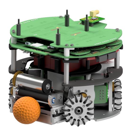
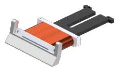
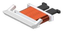
For Robocup 2022 we replaced our chip kicking unit (see in figure 2), substituting the coil and the iron plunger. We introduced changes regarding form and size of the plunger as well as the number of coil windings. This was neccessary due to space constraints.
The core part of the shooting mechanism is a so-called coil gun: When current flows through the coil a magnetic field is generated within it, attracting the ferromagnetic plunger. This accelerates the plunger towards the center of the coil and, more importantly, towards the front of the robot, where it hits the chip kick plate. The entire setup is shown in figure 2.
2 Mechanics: Chip Kick Plunger (continued)
Early testing revealed our design to be limited at about 1.5 m chip distance. This is insufficient for our robots, as it is less than half of the theoretical bound of 4.31 m implicitly given by the rules and the trajectory of a thrown object. This bound was derived under the assumption of a maximum allowed ball speed of 6.5 m s^−1 at an initial angle of 45°. This angle is provided by the design of our chip kick plate [1] to reach the maximum distance.
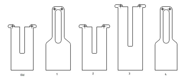
Since the magnetic field of a solenoid with a moving iron core is hard to model, we decided against calculating the problem in favour of testing various plungers. The different plungers are illustrated in figure 3.
2 Mechanics: Chip Kick Plunger (continued)
Two different theories on how to increase the range of the chip kick by changing the plunger were developed and tested. According to the first theory the cross-section of the plunger needs to be increased in order to accelerate the plunger faster. Due to a bigger cross-section, the magnetic field has a larger force application area on the plunger which should accelerate the plunger faster.
The height of the coil is limited by the linear kick and the dribbler, these are mounted on top of the chip kick. Therefore the only way to increase the cross-section of the plunger is to increase its width.
The second theory assumes, that a heavier plunger produces a greater momentum. However, we are not sure whether a heavier plunger leads to a lower speed of the plunger due to Newton's first theorem or whether the larger/heavier plunger accelerates faster because more material can be attracted.
The design of plunger number 2 and 3 is based on our old one (see figure 3). Plunger number 3 is longer to achieve more weight.
It is 45 % heavier than plunger number 2. The front part of plungers number 1 and 4 are longer to increase the material which is inside the coil. The additionally slim part at the back allows an easy kick by hand for test purposes without increasing the weight of the plunger significantly. The different designs including details and the corresponding shoot distances of all plungers are shown in table 1.
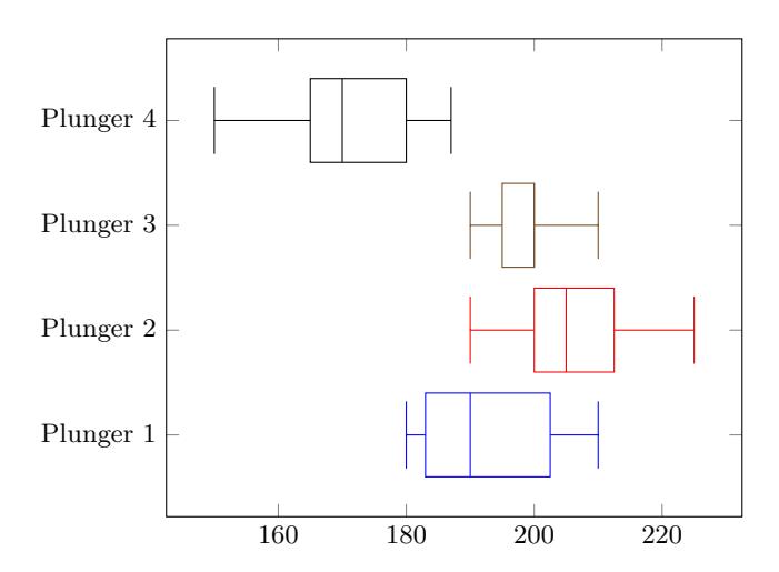
By comparing the wider plungers with the slimmer ones we can see that increasing the width of the plunger does have a positive effect on the distance of the chip kick. The result of plunger number 3 shows that increasing the length and thus the weight neither increases nor decreases the range of the chip kick (see figure 4). The speed of the plunger must therefore have decreased in order to achieve approximately the same momentum with increased weight.
The distances written in table 1 are still below our expectations. The next step will be to investigate the effect of the number of coil windings.
Table 1: Details of tested plungers and shooting test results with 20 chip kicks each.
| plunger | old | 1 | 2 | 3 | 4 |
|---|---|---|---|---|---|
| width | 36.8 mm | 41.0 mm | 41.0 mm | 41.0 mm | 36.8 mm |
| weight | 68 g | 75 g | 77 g | 112 g | 68 g |
| average shoot distance | 150 cm | 186.6 cm | 204.7 cm | 197.4 cm | 172.5 cm |
3 Electronics
(see subsections below)
3.1 Kicker Shielding
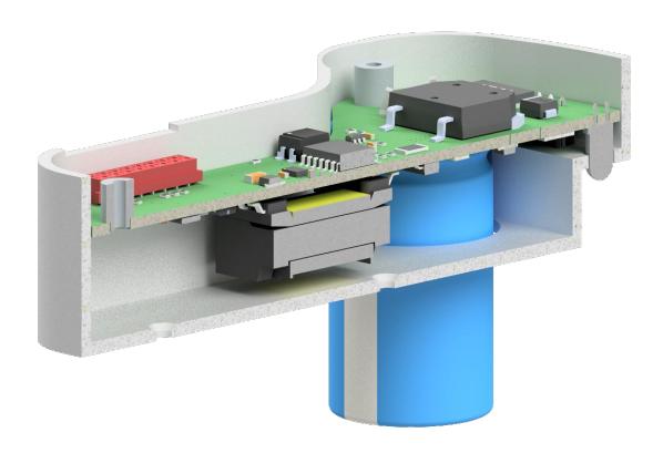
Flashover and Short Circuit Our experience in the last few years showed the need to encase the kicker PCB as it can be seen in figure 5. One of the main reasons is the prevention of short circuits to adjacent electrical components caused by loose metal parts, e. g. screws. Aside from the safety of the electrical components the safety of our team is of the utmost importance. The lack of insulation can be the cause of an electric shock to one of our team members while a maintenance check is performed. Hence the insulation provided by the casing proved to be a necessary safety measure. In all those cases the shielding acts as a contact safety device.
Additionally this protective barrier is a valuable safety measure in terms of electrical flashover. Electric current can cause a short circuit by striking across an air gap between conductors. Such a shortage generates an electric arc as well as intensive heat which can destroy important electrical components.
3.1 Kicker Shielding (continued)
Moreover the electrical components can be easily removed during maintenance because they are fixed to the lid. This not only prevents the technician from touching any electrical components but also makes removing the printed circuit board (PCB) easier. Therefore working on other components of the robot - like the motors of the wheels - is simplified.
For our previous robots, we used coil cables directly soldered to the PCB. In contrast, we now use plugs instead. Those new connectors can simply be plugged into the correct receptable, with the casing preventing the accidental wrong insertion.
Mechanical Stability Besides all the purely electrical and electromechanical reasons for the kicker shell, we also expect additional stabilisation of the capacitors. One of the major flaws of our former design is, that the pads for the capacitors are tearing or peeling off over time, which destroys the kicker PCB. Those large capacitors for shooting have been placed lying on the edge of the PCB. One pin of each capacitor is soldered to its top layer and one to its bottom layer. These two solder joints are the only fixed connections between the PCB and the capacitors and are stressed during driving and dismounting.
To prevent this, the capacitors in the new design are through hole connected, so that any bending loads do not cause the pads to tear off. Furthermore, the kicker board is no longer glued into the robot at the capacitors. This not only improves maintainability, but also reduces the stress that occurs during dismounting. The capacitors are in addition stabilised by suitable recesses in the kicker shell, which should reduce the fatigue caused by vibrations in particular.
Electronic Shielding The encoder measures the magnetic field of the magnets fixed to the motors of the wheels (see [1]). The kicker can interfere with the fields. A prospect for the future can be the shielding of such interference. The basic idea is to add a metal coating on the outer surface of the hull and a clear coating as a outermost layer. The first ensures that interfering signals will not reach the encoder the second layer prevents electrical shortages.
3.2 The Kicker Board in Depth
Introduction In last year's ETDP [2], our team described the redesign of our kicker circuit, i.e., instead of separating the charging and discharging circuit into two different boards, we combined both functions into a single PCB.
Over the past year, we improved this design even further. In fact, our current approach reached a level at which we believe that it would be beneficial to the league and especially new teams to publish the design files. However, as we are convinced that just releasing the files without further documentation would be of little use to the community, this section will give an overview over the schematics and layout of the board.
You can find the design files for our kicker board on our GitHub account[2] The design files are available in the EAGLE format, as PDF, and Gerber. Since it would not be suitable to include the discussed parts of the files within this document, it is highly advised to keep the files open while reading the following sections.
Principle of Operation Before going into the detailed design considerations for the schematics, a rough overview of the general shooting mechanism used by our team will be given. As most of the other teams in the SSL league, ER-Force uses a flyback topology to generate a high voltage of approximately 230 V from our board supply voltage of around 30 V (i.e., 8 lithium polymer cells). With this high voltage, two electrolytic capacitors of 1000 µF each are charged. After being charged, i.e., after about 1.5 s, a shot can be initiated. To do so, the energy stored in the capacitors is discharged abruptly via a solenoid. For details about the mechanical structure of our kicker module see section 2.
Design of the Flyback Converter As stated in the last paragraph, the capacitors are charged to a high voltage by means of a flyback converter. The design of that converter can be found in the upper half of page 1 of our schematics. Compared to other converter topologies, a flyback converter has one major advantage: Its output voltage, in our case 230 V, is galvanically isolated from the input circuit, thus protecting that circuit and the entire robot from potential faults, ringing, and other problems that might arise from a malfunctioning high voltage circuit.
The main design of our flyback converter was created ten years ago as a collaboration with a chair of electrical engineering at our university. As the design of flyback converters might present some problems, we suggest that new teams use existing schematics like that of SSL team TIGERs Mannheim[3] or ours as initial guidance and only start altering the components and values as soon as they have a working prototype. Nonetheless, here are some important thoughts regarding the flyback converter:
- For board voltages below 20 V, INTVCC may be directly connected to the board voltage.
- As the main function of the primary snubber, i.e., of the components D102, C109, and R111 is to convert the parasitic inductive energy stored within the transformer T101 into heat to prevent the drain node of the main-switch Q102 from ringing, the snubber has to be adjusted if the transformer T101 or the main-switch Q102 are replaced by different models.
- The secondary diode D103 has to be of a fast-recovery type. To support the discharge of the diode, a secondary snubber (components R112 and C111) might be used.
- To give parasitic coupling currents between the low and high-voltage paths of the transformer a return path, a coupling capacitor C110 can be used.
- The documentation for the used flyback controller U101 as given in the data sheet is quite comprehensive and it is highly suggested to read it, if any trouble occurs.
Design of the Safety Circuit As already mentioned in section 3.1, the safety of our team members is of utmost importance to us. Therefore, reliable ways to ensure safety in all circumstances are implemented in our current design.
One of these safety measures is the use of a self-discharge circuit, which can be found in the bottom half of page 1. As long as the primary 3.3 V is available, the secondary bipolar transistor Q101's base is shorted to its emitter via an optocoupler, thus preventing any current from flowing through the transistor and across the discharge resistor R103. However, when the 3.3 V break down, e.g., due to disconnection of the PCB, the high voltage capacitors are discharged.
The discharge rate will be determined by the capacitance to be discharged and the discharge resistor R103. It must be fast enough for any human to be unable to reach the PCB during disassembly while the voltage level is still dangerous.
However, as transistors may fail eventually, another safety measure was installed, which is as fail-safe as possible: An LED D101 and a resistor R104 in parallel to the main capacitors. Now, the presence of high voltages is not only indicated visually but a permanent discharge path is also provided.
The Kicker Circuit With the electric circuits outlined so far, the main capacitors can be charged and safely discharged. The only missing part is the kicker circuit, which can be found at page 2. Since the circuits for the linear and chip kick are identical, only the linear kick will be described.
As explained in the theory section, when shooting, the capacitors are discharged abruptly via solenoid coils. To do so, we use an IGBT Q202, i.e., a power transistor. The gate of that transistor has to be driven with strong currents, as the inductive load connected to it via connector J303 (page 3), i.e., the solenoid coil, will otherwise damage or even destroy the IGBT the moment the transistor turns off, as the current through the coil cannot cease instantly.
Therefore, we use a gate driver U301 to control the IGBT. However, as this component needs an external gate supply voltage of around 15 V, an LDO U204 is installed. Due the losses of an LDO being proportional to the difference between its input and output voltages, using it for converting 230 V to 15 V may sound like a very bad idea. However, thanks to an optional protection resistor R213 and the fact that shots happen only scarcely, the LDO proofs to be a compact and lasting solution for the task. To furthermore protect the transistor from damage, a freewheeling circuit consisting of resistor R212 and diode D202 is installed, as well as diode D204 which protects the IGBT from recuperating currents.
Finally, the gate driver is controlled via an optocoupler OP202, so that the galvanic isolation provided by the flyback converter is maintained. In between the optocoupler and the gate driver lies a low pass filter. Without this filter, noise created from the flyback converter might couple into the signal lines, leading to high-frequency shoot signals, which overload the LDO, letting the gate voltage collapse, stopping the gate driver from fully turning on the IGBT and hence ultimately destroying the transistor. Therefore, the low pass filter should dampen the noise to a negligible level. Yet, the cutoff frequency has to be chosen wisely, as lower frequencies cause a greater delay in the shot. During this delay, the ball can travel distances of several 0.1 mm, which might be undesirable.
Miscellaneous The previous paragraphs described the most important part of the kicker board. However, there do remain some minor parts of the circuit that were not yet discussed. These parts are as follows:
- The pinout of the input connector is designed to be symmetrical for the board to not pose a threat when the input connector is plugged in the wrong way.
- The three signals KICK_LINEAR, KICK_CHIP and CHARGE are all powered by 3.3 V buffers SN74LVC2G34. In contrast, DISCHARGE is only powered by an open-collector, hence, in case the input connector is plugged in the wrong way, the board will be rendered incapable of charging.
- For power line decoupling, a compromise regarding the ESR[4] has been taken: While ceramic capacitors do have great ESR and hence great Q values, this might lead to oscillations along the power line due to wire inductance. On the other hand, aluminum capacitors do have very bad ESR thus not providing enough compensation for high frequency surges. Therefore, a polymer capacitor C101 has been chosen, providing a great DC bias characteristic and high capacitance while having a decent ESR.
- The high voltage is measured via a delta-sigma ADC. While this is utmost overkill, the chip has the great advantage of outputting its measurements directly as a digital LVDS signal, making it very robust against noise. The clock signal of the ADC is generated locally via a differential clock to reduce the high-frequency signals transmitted via the main connector.
- For the high voltage part of the board, except for the main capacitors, only SMT components have been chosen. This greatly simplifies the board layout when it comes to clearance requirements and improves unwanted couplings.
Layout Considerations Now that the schematics have been fully discussed, important notices about the layout of the kicker board can be given:
- Introduce a clear board separation between the high voltage and low voltage parts. Note that there is a pin at the low voltage side of the transformer that is connected to its high voltage winding.
- Use separate net classes for different voltage levels. For our design, we used five net classes: low voltage, mid voltage (only for node connecting R107, D102, T101, and Q102), high voltage minus, high voltage swing, and high voltage plus. The three high voltage classes do have clearances of 1.25 mm to other classes.
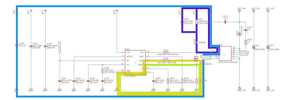
- Optimize the flyback converter layout for short paths. The most important paths to be minimized are shown in figure 6. If possible, you may additionally minimize the pin-to-ground-to-pin paths of the RREF and RFB pins.
- Keep as much copper area as possible to prevent breaks in return paths.
- Use via fencing and stitching and avoid using vias anywhere else
- Place the low-pass filters for the shoot signals as close as possible to the gate driver
- Minimize the high voltage "shoot" paths, i.e. from the main capacitors to the coil connector to the IGBT back to the capacitors, as well as from the coil connectors to the freewheeling path back to the connector.
- Make the shoot paths as thick as possible.
- Place the LED at a spot where it can be easily seen, especially during disassembly.
4 AI: Tracking Robot-Ball Interactions
(see subsections below)
4.1 Motivation
Tracking is the task of estimating a realistic world state from the noisy data obtained from the SSL-vision[3]. It has four main objectives:
- Reducing noise on the position data
- Estimating the velocities for all objects
- Removing artifacts created by the SSL-vision such as the ball position being projected to a different ground position while flying
- Extrapolating the world state into the future
Objectives 1-3 are fairly self-explanatory, but objective 4 might require a short explanation: The vision data at time t is - necessarily - going to be outdated by time t1 once it arrives at our machine. The robots themselves are also going to have a delay t2 until they can receive and start acting on our commands. Therefore our tracking has to estimate the situation at time t + t1 + t2, to avoid acting on outdated information.
Our general approach for the tracking has already been published in our previous TDPs [4,5], and our approach for estimating the 3D ball positions and eliminating the corresponding artifacts from a flying ball has been presented in our 2017 ETDP [6]. As already stated in our earlier TDPs, we use a variant of a Kalman [7] filter to process ball and robot detections. Kalman filters are commonly used in the SSL [8,9,10] and are a good fit for objectives 1, 2 and - for a small duration and assuming an undisturbed ball - 4. However, it is not well suited for objective 3. Therefore, we detect flying balls using a separate algorithm and ignore the output of the regular Kalman filter during the flight.
4.2 Problems of Kalman filters
As other teams have previously observed, using a Kalman filter comes with additional secondary challenges. These originate from robot-ball interactions, as the traditional Kalman filter for the ball is unaware of the robots. We are aware of two teams sharing these issues and their solutions to some of these interactions [11,12].UBC Thunderbots [11] note that their Kalman filter had a latency of up to 1 second for a recently shot ball, so they abolished their Kalman filter and use a particle based filter instead. NEUIslanders [12] noted that in order to fix issues with the direction of the ball velocities after a volley, they had to 'consider ball velocity dynamics as practically undetermined if the ball gets too close to any robot'.
Additionally, we observed the following issues with our Kalman filter:
- A robot can occlude the ball if both are in close proximity to each other. In many of these cases, our Kalman filter is unable to correct these occlusions.
- When predicting the ball position into the future (see objective 4), the prediction does not take into account the possibility of the ball being stopped by a robot.
As an example for the second point, consider Figure 7. In this example, the ball is shot at a stationary robot and then stopped by that robot. The purple circle indicates the ball detection sent by the SSL-vision while the orange circle is the future ball predicted by our Kalman filter. It can be seen that the predicted ball is inside the robot for some time until the raw ball detections arrive at the robot and the ball is stopped. This behavior is undesirable since it may cause problems with AI code that uses the predicted world state. Note that in extreme cases, the predicted ball position can even be behind the robot.

4.3 Expanding Kalman filters with additional heuristics
Since these problems highlight the relevance of solving robot-ball interactions in the tracking, we dedicate the remainder of this section to explain our heuristic tracking filter for these kinds of interactions. The ball-robot interactions were implemented as a series of heuristics that operate on the predicted world state created by the regular ball Kalman filter. The Kalman filter tracking the ball is therefore left unchanged, with the heuristics being implemented as a wrapper around it.
We decided against replacing the Kalman filter with a completely new approach, since it is an established concept that is already proven to work extremely well in most cases, except for the select situations described above. Therefore building on the already existing Kalman filter was deemed more efficient than testing experimental ideas, which might or might not be able to adress these issues.
The heuristics are built on non-trivial assumptions. Consequently, the predicted world state can be incorrect when one of the inbuilt assumptions does not hold for a given situation. While in our experience these cases are either exceedingly rare or easy to handle in our AI, this has to be taken into consideration as a potential problem of our approach.
The primary goal of this filter is to ensure that the tracked ball is never inside a tracked robot. Note that in some cases it is impossible to guarantee that the ball is never inside a robot since two tracked robots may overlap with the ball between them. In this case, it is acceptable for one robot to intersect the ball. As a second goal, the tracked ball velocity has to be corrected such that it is more realistic during dribbling or volley shots.
To achieve these two goals, the heuristic filter has multiple modes. Each mode represents a way for a robot to interact with the ball. If no robot-ball interaction is detected, the results of the regular ball Kalman filter are returned.
4.3 Expanding Kalman filters with additional heuristics (continued)
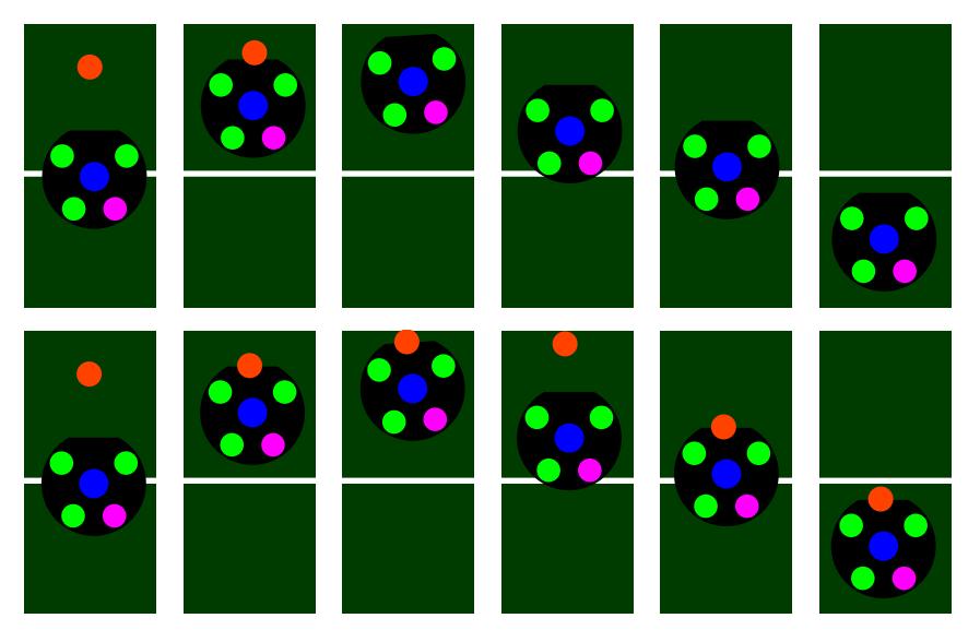
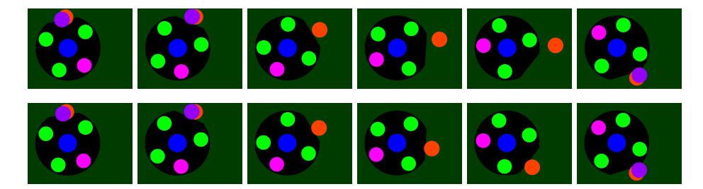
Mode one: dribbling The first mode is for dribbling while the ball is invisible. It activates when a robot intersects with the predicted ball position and ends when the ball becomes visible again. If the robot is driving in the direction of the ball, the assumed ball position is pushed along with the robot. During this time, a position is updated that keeps track of where the ball would be pushed to in case the robot does not have the dribbler active. If the robot then drives away from the ball (or its updated push position), it is first assumed to stay at the position it was pushed to. This only changes once the calculated push position leaves the shadow of the robot and the ball is still not visible. The shadow size of the robot can be calculated by intersecting the ray from the ball position to the relevant camera with the robot hull. This can be easily done without 3D geometry calculations. If the pushing position is visible from the camera but the ball is not visible yet, the robot must be dribbling the ball. Therefore, the predicted ball position is snapped back to the dribbler of the pushing robot, staying there until the real ball becomes visible. During dribbling, the predicted ball velocity is set to the velocity of the robot. To get the correct result, the angular velocity of the robot has to be factored in for this calculation. An example of this filter mode in action can be seen in Figure 8. The robot pushes the ball up to the field border and then pulls it back into the field. In the upper row, the original behavior with the Kalman filter is shown. The ball is invisible during the whole duration of pulling the ball. In contrast, the lower row shows the described heuristic filter in action. The ball position is estimated mostly correctly, except for the 4th frame, where the ball is not yet snapped back to the robot.
Note that this behavior is intended. When the robot drives back from pushing the ball, there are two options. Either the robot is dribbling the ball back or not. Both scenarios happen frequently enough to not be irrelevant. We decided on the assumption that the ball is not initially dribbled because it works better with the remainder of our strategy.
Mode 2: collisions A different mode is used when the predicted ball intersects with a robot but the ball is currently still visible. This often occurs when a fast ball reaches a robot, during dribbling, or during dueling when the ball is still visible. Figure 7 shows an example for when this filter would activate. This mode is detected by checking the line segment between the last ball detection and the predicted ball for any intersections with a robot. If it intersects a robot, the predicted ball position is set to the first intersection. It is not sufficient to check if the predicted ball is in a robot since the predicted ball can already be behind the robot while the last ball detection is still in front of it for fast moving balls. If both the last ball detection and the predicted ball are in a robot, the predicted position is projected out of the robot along the relative velocity between the ball and robot. This case often happens during dribbling or duels with other robots. Note that in this mode, the predicted ball velocity is not set to the robot velocity. Since the ball is still arriving at the robot, setting the velocity to potentially zero causes problems with our AI.
Some edge-cases For volley shots, a separate check was created to ensure that the outgoing ball has no sideways velocity originating from slow updates by the Kalman filter. Such shots are detected by the predicted ball having intersected a robot, activating the second mode, and then having a ball detection go further away from the robot. In this case, the filter is reset to the velocity equivalent to the shot velocity in this one frame.
Another defect originating from the velocity of the Kalman filter is when a standing ball is partially occluded by a robot shadow. If the robot then slowly drives towards the ball, less of the ball is visible each frame. This results in the ball detections shifting slightly away from the robot, even if the robot has not yet reached the ball. As a result, the Kalman filter estimates a low velocity away from the robot. When the ball then becomes invisible, this velocity is maintained, moving the predicted ball further away from the robot. This effect often occurs during ball placements since the robot shadow is the largest at the field borders. The result is that the dribbling filter can not activate, since the predicted ball never intersects the robot. This problem is fixed by resetting the filter to the last observed ball position when the situation is detected.
A last special case occurs when a robot dribbles the ball and rotates on the spot. During this rotation, the ball can become invisible and is predicted to travel away from the robot by the Kalman filter. The upper row of Figure 9 shows the output of our Kalman filter in this situation. Since the predicted ball strongly deviates from the true ball position, an additional heuristic check is required to handle this situation. The desired behavior is that the ball continues rotating together with the robot until it becomes visible again. However, the previously described heuristic filters can not activate in this situation since the robot is not pushing the ball and the line segment between the detections and predicted ball also does not intersect the robot. Therefore, this new heuristic is activated by the ball being in a similar spot in the dribbler of a robot for multiple frames and then becoming invisible. If this happens, the last observed relative position between the robot dribbler and the ball are used to estimate the current predicted ball position. The predicted ball velocity is set to the robot velocity like in the dribbling ball mode. The results of this filter can be seen in the lower row of Figure 9. In the frames where the ball is invisible, the predicted ball position is correctly kept in the robot dribbler.
5 Conclusion
In this ETDP, we presented improvements to our shooting ability, both in hardware and in software. On the mechanical side the form and size of the plunger was optimized for chip distance. The electronics part describes our new kicker shielding and gives an in depth guide to our kicker circuit, which is openly available from now on. The strategy section explains improvements in our tracking abilities from filters that are especially designed to handle edge cases where the standard Kalman filter fails. We hope the information is understandable and useful to you and we are looking forward to hearing your feedback.
References
- Engelhardt, T., Heineken, T., Kühn, T., Lindner, J., Schmidt, M., Schofer, F., Seifert, C., Stadler, M., Wegmann, L., Wendler, A.: ER-Force 2019 Extended Team Description Paper. (2019)
- Bergmann, P., Engelhardt, T., Heineken, T., Hopf, V., Schmid, M., Schmidt, M., Schofer, F., Schuh, K., Stadler, M.: ER-Force 2022 Extended Team Description Paper. (2022)
- Zickler, S., Laue, T., Birbach, O., Wongphati, M., Veloso, M.: Ssl-vision: The shared vision system for the robocup small size league. In: Robot Soccer World Cup, Springer (2010) 425–436
- Bauer, F., Blank, P., Bleier, M., Dohrn, H., Eischer, M., Friedrich, S., Hauck, A., Kallwies, J., Kugler, P., Lahmann, D., Nordhus, P., Reck, B., Riess, C.: ER-Force Team Description Paper for RoboCup 2011. (2011)
- Kallwies, J., Dirauf, S., Nordhus, P., Kerschbaum, S., Friedrich, S., Bleier, M.: ER-Force Team Description Paper for RoboCup 2012. (2012)
- Lobmeier, C., Blank, P., Bühlmeyer, J., Burk, D., Danzer, A., Kronberger, S., Niebisch, M., Eskofier, B.M.: ER-Force Extended Team Description Paper RoboCup 2017 (2017)
- Kalman, R.E.: A new approach to linear filtering and prediction problems. Transactions of the ASME – Journal of Basic Engineering 82 (Series D) (1960) 35–45
- Rodríguez, S., Rojas, E., Pérez, K., López, J., Quintero, C., Calderón, J.M.: STOx's 2014 Extended Team Description Paper. (2014)
- Pour1, S.M., Mehrabi, V., Saeidi, A., Sheikhi, E., Kazemi, M., Pahlavani, A., Behbooei, M., Ghanbari, P.: Parsian Extended Team Description for Robocup 2013. (2013)
- Yasui, K., Nunome, Y., Sasai, H., Matsuoka, S., Adachi, Y., Ito, M., Kobayashi, K., Murakami, K., Naruse, T.: RoboDragons 2013 Extended Team Description. (2013)
- MacDougall, M., Ellis, G., Hashemi, A., Jackson, E., Lip, O.C., Ivanov, N., Petrie, J., Tonks-Turcotte, K., Sousa, C., Lai, K., Xu, B., Li, Q., Goto, E., Deutsch, D., Buonassisi, A., Lee, M.: 2018 Team Description Paper: UBC Thunderbots. (2018)
- Abiyev, P.D.R.H., Makarov, D.P., Cagman, A., Aytac, E., Burge, G., Turk, A., Akkaya, N., Yirtici, T., Say, G., Yilmaz, B.: NEUIslanders Team Description Paper RoboCup 2019. (2019)