GreenTea 2023 Team Description Paper
Hirotaka Sato, Naoyuki Okamoto, Akito Ito, Shun Kayaki, Naoya Sugishita, Shoma Nakaaki, Tomoki Nakao, Yuki Nishimura, Yuto Hara, Kohei Fujita, Rintaro Yuri
The Open University of Japan; Graduate School of Informatics, Kyoto University; Graduate School of Electrical and Electronic Systems Engineering, Nagaoka University of Technology; Faculty of Computer Science and Systems Engineering, Kyushu Institute of Technology; Faculty of Engineering, Aichi Institute of Technology; Graduate School of Engineering, Osaka Institute of Technology; Undergraduate course program of applied mathematics and physics, Kyoto University; Graduate School of Science and Technology, University of Tsukuba; Faculty of Information Science and Technology, Osaka Institute of Technology
Abstract GreenTea is a student organization founded in 2019. Since this is our first TDP submission, we will give an overview of the robot. In particular, We will elaborate on the unique machine and the motor drive unit. Many of the mechanical parts of our robot are manufactured with a 3D printer, which helps to reduce weight and increase space efficiency. BLDC motors mounted inside the Omni wheel directly drive the robot's movements. We also briefly introduced the entire circuitry and AI system. We look forward to seeing the robot in competition.
Keywords: RoboCup, small size league
1 Introduction
GreenTea is a group of students founded in 2019. Members are dispersed throughout Japan and meet online once a week. Since we do not have a permanent field set up, we usually develop the assigned tasks at home, and we have occasional "practice sessions" where we rent a local meeting room for a few days to set up the field, integrate the elements, and check the operation on a real machine. As this is the first TDP contribution, we will overview the robot's structure and technology from a machine, embedded system, and software aspects. Our robot has a unique design for miniaturization. We are focusing on developing a game AI system that has yet to reach its full potential. This paper will detail a particularly unique machine and motor drive unit. Other elements will only be introduced, but stay tuned for the next TDP.
2 Mechanical
2.1 Overview
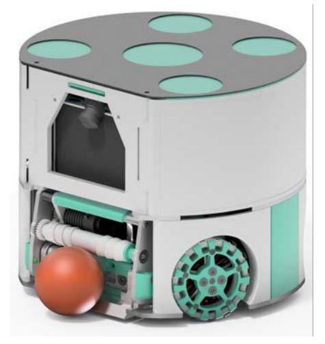
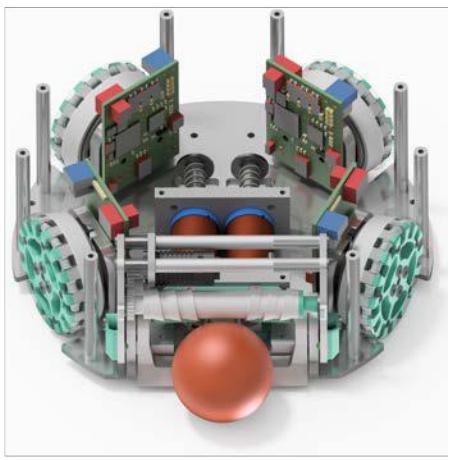
Fig. 1 shows the outline drawing of our 5th generation robot called "Sanran". The main specifications are shown in Table 1. Three features of our robot exist, 1: In-wheel drive unit, 2: Parallel kicker unit, and 3: Structure with full use of a 3D printer. The structure of the dribbler is based on ZJUNlict. Our robot is shown in Fig. 1. Table 1 shows the equipment used.
Robot specifications.
| Robot version | Ver. 5 Sanran(燦爛) |
|---|---|
| Dimension | ϕ178 × 148 mm |
| Wheel motor | SunnySky V2806 KV400, Direct drive |
| Wheel diameter | 55 mm |
| Sub wheel pcs | 15 pcs × 2 layers † |
| Encoder | AS5048A 14 bits absolute encoder |
| Dribbler Motor | Rocket Mini Z, 15:24:24 |
| Dribbler bar diameter | 12 mm |
| Kicker | Straight / Chip |
| Coli turns | turns × 6 layers |
| Power Supply | Lipo 4 cells 1800 mAh |
† at V2806 motor (Alternative option: 15 pcs × 1 layer at V4006 motor)
2.2 In-wheel Motor Unit
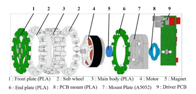
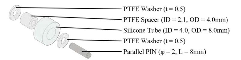
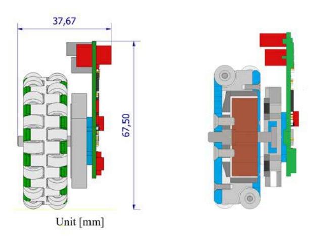
In-wheel Motor Unit is characterized by its ultra-compactness, lightweight and strength. The component parts of this unit are shown in Fig. 2 and Fig. 3. Some teams use industrial brushless motors such as Maxon EC Flat motor or Nanotec motor. These motors are expensive and heavy. On the other hand, we used Sunnysky's V4006 or V2806, which are brushless motors for drone. They are lower cost, lighter weight, and smaller size. We took advantage of these features to make an ultra-compact Motor unit without sacrificing mobility. The unit size is shown in Fig. 4.
Front-plate, Sub-wheel-mount, and End-plate are made from Polylite PLA using 3D-printer, because Components of the unit have complex shapes. The strength of the 3D printed parts is weaker than that of the machined parts. To increase shock resistance, the rotor being outside of the motor is press-fitted into Sub-wheel-mount. In this way, the shock is absorbed not by the 3D printed parts but by the metal outer rotor. This unit did not break at RoboCup JapanOpen 2022.
2.3 Motor Selection
This section compares the motors used in the In-wheel Motor Unit with those commonly used in RoboCup-SSL. Industrial motors from maxon and Nanotec are often used in SSL. On the other hand, our team uses SunnySky drone motors. Drone motors are lighter and cheaper than other motors (see Table 2). Table 3 shows a comparison of the maximum torque calculated from the torque constant and maximum current of these motors. Since SunnySky motors are only given a KV value and not a torque constant $K_M$, Eq. (1) is used to convert the KV value to a torque constant.
$$K_M [\text{mN} \cdot \text{m/A}] = \frac{30000}{K_N [\text{rpm/V}] \times \pi}$$ (1)
Table 3 confirms that drone motors can generate greater torque than other motors. SunnySky's maximum current is limited to 60 seconds, but SSL does not accelerate continuously for more than 60 seconds, so it is treated the same as the normal maximum current. Continuous rapid acceleration and deceleration may cause heat generation problems.
Motor Specifications.
| Name | Nanotec | maxon | SunnySky | SunnySky |
|---|---|---|---|---|
| DF45L024048-A2 | EC45flat 200189 | V4006 KV320 | V2806 KV400 | |
| KV [rpm/V] | 201.67 | 375.00 | 320.00 | 400.00 |
| Winding resistance [Ω] | 0.64 | 1.40 | 0.23 | 0.61 |
| Size [mm] | ϕ42.9 × 37 | ϕ42.8 × 47.6 | ϕ43.6 × 23.4 | ϕ35 × 23.4 |
| Weight [g] | 150 | 75 | 66 | 47 |
| Price [$] | 115.7 [6] | 109 [5] | 52.99 [9] | 28.99 [8] |
Comparison of maximum torque of motors
| Name | Nanotec | maxon | SunnySky | SunnySky |
|---|---|---|---|---|
| ${\rm DF45L024048\text{-}A2}$ | EC45flat $200189$ | $\rm V4006~KV320$ | $V2806 \ KV400$ | |
| Rated voltage [V] | 24 | 12 | 24 | 15 |
| Peak current [A] | 9.5 | 2.16 | 15 | 10 |
| Torque constant $[mN\cdot m/A]$ | 36.90 | 25.46 | 29.84 | 23.87 |
| Max torque $[mN \cdot m]$ | 350.55 | 55.00 | 447.62 | 238.73 |
2.4 Parallel Kicker Unit
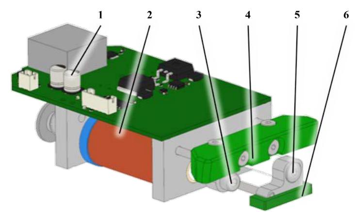
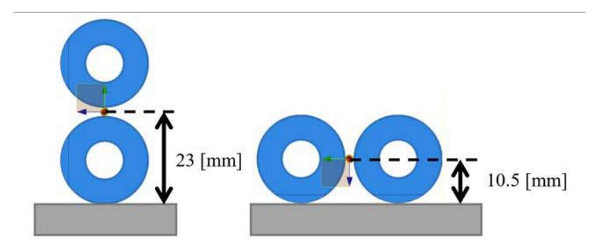
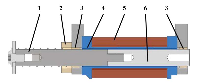
This unit structure has been developed for our robot 2nd generation and is characterized by the placement of the chip kicker and straight kicker "parallel" to the ground in shows Fig. 5. This structure contributes to the robot's low center of gravity. As shown in the Fig. 6, this mechanism can lower the center of gravity by more than 50 %. Furthermore, Boost-Board and mechanical-parts-assy are integrated into a single unit, making them easy to maintain. As shown in Fig. 7, Our solenoid structure is an arrangement of TIGERS Mannheim's one. We made the plunger using Misumi's iron spacers and Hirosugi's aluminum spacers to reduce costs. The plunger diameter is smaller than the original and the solenoid thrust is lower. Therefore, the number of coil turns was increased. (73 turns × 6 layers of ϕ 0.5mm UEW)
3 Embedded
3.1 Overview
The robot needs to reflect the commands it receives from the AI system in its movements. For this purpose, our robot is equipped with six different boards: a main board, a boost kick board, an image processing unit, a wireless communication unit, a motor drive board for traveling, and a motor drive board for dribblers. Chapter 3 describes the function of Main board , wireless communication unit and Motor Driver.
3.2 Main Board
The main board is responsible for sending commands to each board based on signals received from the AI system and for power management. It receives commands received by the wireless communication unit via UART (Universal Asynchronous Receiver/Transmitter). Based on the received data, the microcontroller sends commands to the motor drive board for driving, the motor drive board for the drivetrain, and the voltage booster kick board. The main board has two microcontrollers: STM32H7 for control and communication and STM32F0 for power management. The main board has a CNA (Controller Area Network) interface for communication with the running motor driver, a PWM output for ESC used as the motor driver for the drivetrain, and a parallel communication function for the voltage booster kick board. The main board consists of two boards: an upper board that handles control signals and a lower board that handles high current.
3.3 Communication
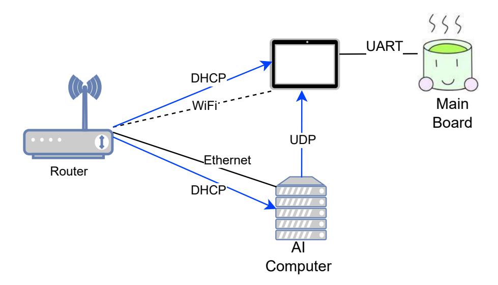
Overview An overview of the network for receiving commands from the AI system is shown in Fig. 8, where WioTerminal is used as a wireless communication unit, connecting the computer running AI and each robot's wireless communication unit, WioTerminal, to a network of WiFi routers.
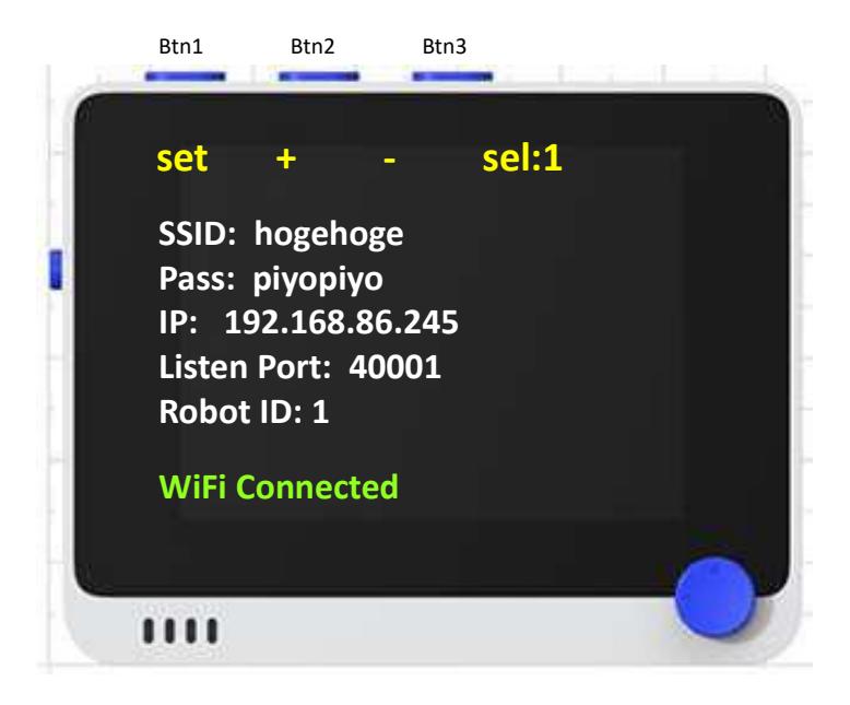
WioTerminal WioTerminal is a microcontroller board from SeeedStudio with a 2.4GHz/5GHz WiFi module, a 2.4-inch LCD, and three user buttons.
Fig. 9 shows the contents displayed on the screen of WioTerminal, which is used as a wireless communication unit. The robot ID can be selected by Btn2 and Btn3, and the selected ID can be set by Btn1 to reduce the time and effort required to change the ID during operation. The ID is written to the internal flash memory, and the ID information is retained even when the robot is rebooted. Other information necessary for connection confirmation is displayed on the screen.
Network The computer on which AI is running and WioTerminal are assigned IP addresses using the DHCP function of the WiFi router. Instruction packets from the AI system are broadcasted to the port number of 40000+robot ID assigned according to the ID of the robot to which the instructions are sent. The robot ID is set in WioTerminal, which listens to the port corresponding to the robot ID to receive commands.
3.4 Motor Driver
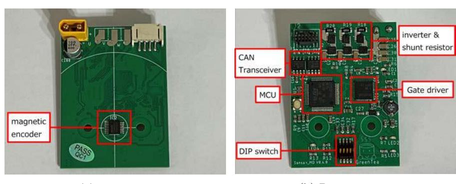
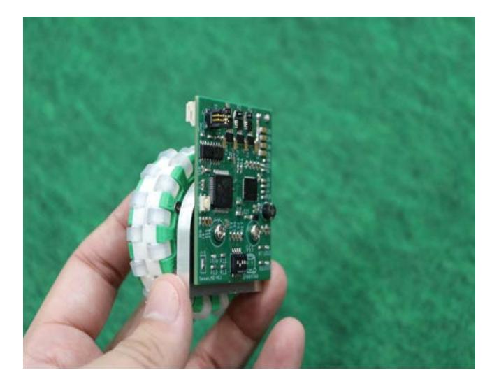
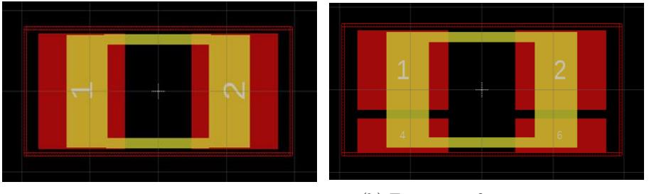
Circuit The appearance of the motor driver is shown in Fig. 10. The motor driver circuit is wired on a two-layer board and has an external dimension of 40 × 55 mm. The structure directly fixed to the back of the motor contributes to the miniaturization of the Omni-Wheel Unit (see Fig. 11). It has CAN-bus as an interface to the main board. The STM32F446RE from ST is installed as the MCU for control. A 3-phase inverter consisting of six MOSFETs (PSMN011-60MLX) is used to output voltage to the motor. For current control, current detection is performed by placing shunt resistors on the low side of each phase leg. The prototype board had poor current control performance due to noisy current detection values. Therefore, the footprint of the shunt resistor was changed as shown in Fig. 12 and the wiring was adjusted. As a result, noise was reduced and current control performance was improved. The magnetic encoder is mounted on the motor driver board, eliminating the need for wiring with noise-sensitive cables. DIP switches mounted on the board are used to set the ID for CAN communication. No need to rewrite the program when changing IDs, making it easy to replace the board. Even if a circuit or motor fails during a game, the entire omni-wheel unit can be replaced immediately without reprogramming.
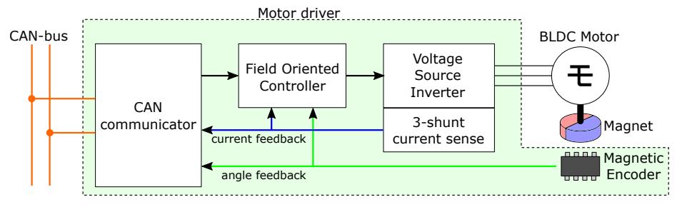
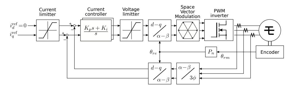
Control Software An overview of the motor drive system is shown in Fig. 13. The current command is sent from the main controller to the motor driver via the CAN bus. The motor driver sends back the current, angle, and speed status to the host controller. Transmission frequency of CAN communication is 1000 times per second. In the case of this paper, The motor speed is controlled by the host controller, and only the current is controlled by the motor driver. This eliminates the need for tuning dependent on machine parameters (Mass, Inertia, etc.) at the motor driver and improves maintainability. FOC(Field Oriented Control) enables highly efficient motor drive and reduces heat generation of the motor. The control algorithm operates at 10 kHz, synchronized with the PWM frequency. The current is detected by a 3-shunt method. The structure of the FOC is shown in Fig. 14. The detected values of the 3-phase currents are converted to the rotating rectangular coordinate system (d-q coordinates) using the magnetic pole position obtained by the magnetic rotary encoder. Current control by the PI controller is performed on the d-q coordinates, and the d-qaxis voltage command value is again converted to 3-phase voltage and output to the PWM inverter. The relationship between the current $i_d$, $i_q$ and output torque $\tau_m$ in d-q coordinates is expressed as Eq.(2), where $P_n$ is the number of pole pairs, $\Psi$ is the flux linkage, and $L_d$, $L_q$ are the inductance in the d, q axes.
$$\tau_m = P_n \Psi i_q + P_n \left( L_d - L_q \right) i_d i_q$$ (2)
Since the effect of the second term is small for our motor, the d-axis current zero control was selected because of its simplicity.
The motor specifications used are shown in Table 4. The controller specifications are shown in Table 5.
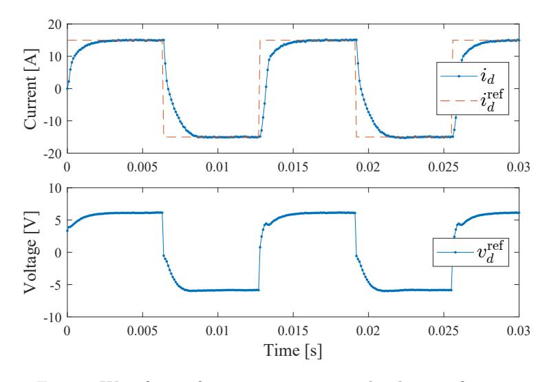
Experiment of Current Control To confirm the performance of current control, an experiment was conducted in which a square-wave current command value of ±15 A was given to the d-axis. When current is applied only to the d-axis, no torque is generated, so there is no need to constrain the motor. A plot of the current response vs. the voltage command value is shown in Fig. 15. In the steady state, the current follows the command value without steady-state deviation. It can be confirmed that the current transient response converges sufficiently in about 2 ms.
Motor specifications.
| SunnySky | SunnySky | |
|---|---|---|
| V4006-320KV | V2806-KV400 | |
| Resistance(R) | 0.27 [Ω] | 0.35 [Ω] |
| d-axis inductance(Ld) | 49 [µH] | 65 [µH] |
| q-axis inductance(Lq) | 62 [µH] | 95 [µH] |
| Flux linkage(Ψ) | 0.030 [Wb] | 0.024 [Wb] |
| Pole pairs(Pn) | 12 | 7 |
Controller specifications.
| PWM carrier freq. $(f_c)$ | 10 [kHz] |
|---|---|
| Sampling period $(T_s)$ | 100 [$\mu$ s] |
| Current control bandwidth $(\omega_c)$ | 2000 [rad/s] |
| Current limit(V4006-320KV) | 15 [A] |
| Current limit(V2806-400KV) | 10 [A] |
4 Software
4.1 MATCHA
This chapter describes the software "MATCHA", which is responsible for everything from data received from SSL-Vision and Referee to commands to the robot.
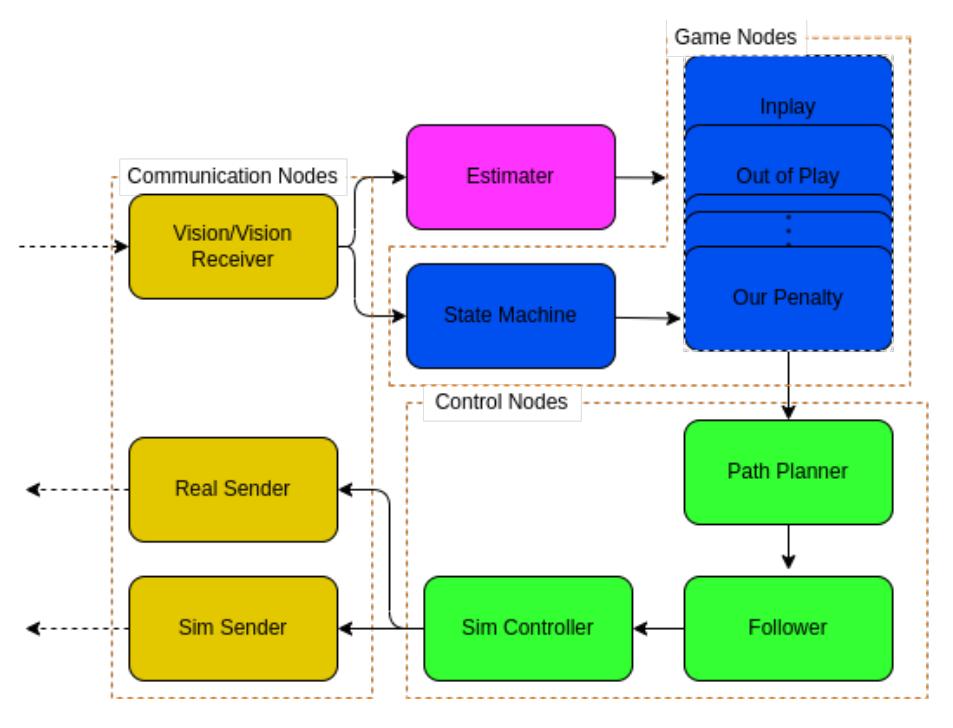
Structure MATCHA is our software components running on ROS (Fig. 16). First, there is the estimator, which receives data from Vision, filters the position and posture of the robots, and converts them into a data format that can be handled within MATCHA. The "Path Planner" generates a path from the target position and posture of each robot generated by the game node, and the follower generates the target speed and position and posture for the robot from the path. In the case of a simulation using GrSim, "Sim Controller", which performs feedback control using the current speed and position-posture and target speed and position-posture as inputs, and "Sim Sender", which sends the results to GrSim, are activated. When operating the actual robot, a "Real Sender" that directly sends the target position and posture to the robot is activated instead of them. tf is used to manage the coordinates of the robot and ball.
Role MATCHA enables each robot to play a game in the in-play condition by assigning one of the following five Roles to each robot. Specifically, the number of robot in each role depends on the position of the ball in the field, and each robot is associated with the role so that the sum of the squares of the moving distance of robots is minimized.
GK Goalkeeper robot to stop the opponent from scoring in our penalty area.
DF Defense robots interfere with their scoring outside of our penalty area.
MF Midfielder robots pass the ball forth to increase opportunities for scoring.
AK Attacker robots try to score.
IN Interceptor robots prevent their robot from passing ball each other.
Development Environment Since the entire program is composed of ROS, and since development is performed by multiple menbers using git and GitHub, the development environment is built according to the preferences of each developer so that these functions can be used. The program consists of approximately five people, and each node is assigned to a different person in charge of development.
4.2 Local Camera System
The robot has a camera in front of itself to detect the ball and estimate its position. The ball detection system was implemented based on Deel and Jut, and the coordinate transformation system was additionally implemented.
Configuration A Raspberry pi camera (g) was used as the camera. The image sensor used is the OV5647. The camera processing was done using the Raspberry Pi 4B. The camera was installed so as to look down at the ground from the upper front part of the robot.
The camera resolution was set to 640 × 480 and the frame rate was 90fps. The YUYV codec was used.
Generating a Grayscale Image The YUYV format is composed of a luminance component and two chrominance components(Cb, Cr). By calculating the difference between these chrominance components, a grayscale image of "orangeness" can be obtained. Since the ball is orange and the field color is green, these contrasts are emphasized by this process. It is also less susceptible to the influence of the environment because it does not depend on brightness.
Ball Detection Several scanning lines along the X-axis were prepared and the differential image on the scanning line was calculated. Then, those exceeding the threshold were detected as contours. The center positions in the X-axis were calculated from the contour positions detected on each scanning line. Next, Yaxis scanning lines were drawn at each center position and contour positions were detected in the same way, and the center positions in the Y-axis were calculated. As a result, multiple estimates of the ball center are calculated which are then averaged to obtain a single estimate point.
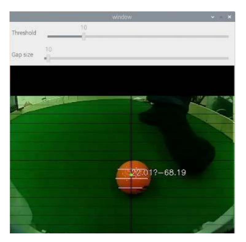
Coordinate Transformation The estimated point obtained is in screen coordinates. Therefore, coordinate transformation is performed to convert it to world coordinates. However, converting from screen coordinates to world coordinates is an ill-posed problem. Therefore, the constraint that the ball's z coordinate (height) is always 0 was introduced. The OpenCV's calibrateCamera function was used to estimate the camera parameters. Figure 17 is one of the results of this process.
The integration of this ball detection mechanism and the Vision or the robot control is currently being researched.
References
- Camera calibration and 3d reconstruction. https://docs.opencv.org/2.4/modules/calib3d/doc/camera_calibration_and_3d_reconstruction.html
- Fabio Seel, Sabolc Jut: On-board computer vision for autonomous ball interception. https://download.tigers-mannheim.de/papers/2019-BallIntercept_TC-Seel_Jut.pdf (2019)
- Hirohashi, T., Hotta, R., Tasaka, T., Matsumoto, Y., Tomioka, D., Naito, Y., Wakao, K., Takagi, T., Murase, S., Wakabayashi, K.: Robocup 2022 team description paper ri-one ssl (2022)
- J. Almagro, C. Avidano, C. Lindbeck, J. Neiger, Z. Olkin, E. Peterson, K. Stachowicz, W. Stuckey, M. White, M. Woodward, G. P. Burdell: Robojackets 2019 team description paper (2019)
- maxon: EC 45 flat Ø42.9 mm, brushless, 30 Watt, sensorless. https://www.maxongroup.us/maxon/view/product/motor/ecmotor/ecflat/ecflat45/200189 (Date accessed: 17.03.2023)
- Nanotec: DF45L024048-A2 – BRUSHLESS DC MOTOR. https://en.nanotec.com/products/1787-df45l024048-a2 (Date accessed: 17.03.2023)
- Ommer, N., Ryll, A., Geiger, M.: Tigers mannheim extended team description paper (2019)
- SunnySky: SunnySky V2806 High Efficiency Brushless Motors. https://sunnyskyusa.com/collections/v-motors/products/sunnysky-v2806-motor (Date accessed: 17.03.2023)
- SunnySky: SunnySky V4006 High Efficiency Brushless Motors. https://sunnyskyusa.com/collections/v-motors/products/sunnysky-v4006-motors (Date accessed: 17.03.2023)
- Texas Instruments Inc.: Current Sensing With <1-µs Settling for 1-, 2-, and 3-Shunt FOC Inverter Reference Design. https://www.tij.co.jp/jp/lit/ug/tiducy7/tiducy7.pdf