KIKS Extended Team Description for RoboCup 2023
Daichi Miyajima, Kosei Naito, Hayato Mitsuda, Kazuaki Harada, Mizuki Nonoyama, Ryo Shirai, Futa Sato, Ryuto Tanaka, Yota Dori, Toko Sugiura
National Institute of Technology, Toyota College, 2-1 Eisei-cho, Toyota, Aichi 471-8525, Japan
www.ee.toyota-ct.ac.jp/~sugi/RoboCup.html
Abstract This paper presents the robot and software system of SSL team KIKS, which is planned to participate in the RoboCup 2023 Bordeaux. In this ETDP, we mainly present our study on the improvement of the dribbling bar, dribbling mechanism and kicker circuit, and prediction of the opponent robot's behavior using machine learning. We describe the weaknesses of the previous generation robot and the improvements to overcome them, including software upgrades. In addition, we overview the study of improving robot position control with on-board cameras and encoders to correspond to Vision-Blackout.
Keywords: RoboCup, small size league, autonomous robot, global vision, engineering education
1 Introduction
Team KIKS has continued to work toward developing higher performance hardware and smarter AI systems. This year, we studied the improvement and extension of ball control performance on hardware, especially on the improvement of the dribbling system. We also experimented with motion control based on the robot's own judgment, using a local vision system and encoders corresponding to Vision Blackout, based on the Jetson Nano introduced last year. In the software, we tried to predict the opponent robot's behavior using machine learning. The results of the experiments are described below.
2 Mechanical system
In RoboCup Small Size League, the dribbling system is very important to realize the strategy of AI, recently. This is because enhanced ball possession and the realization of curved shots lead to an expansion of the strategy. In 2022, we improved the traditional dribbling bar to increase ball keeping ability by simply splitting in the center of the bar[1]. The improvement was very simple and could be done in a very short time. As a result, the ball keeping ability of the robot was improved, but its performance is still not sufficient and several problems remain to be solved. In this section, we describe the trial experiments we performed to solve those problems and the results of the verification.
2.1 Dribbling bar
The dribble bar [1] proposed in the ETDP 2022 is made by cutting a rubber pipe of uniform thickness. Due to the relatively hard material, when the ball was caught at the end of the bar, it bounced and could not hold the ball. In addition, the ball could not be moved to the center of the bar, and sufficient rotational and holding force could not be given to the ball. If the ball could be moved to the center of the dribbling bar in a short time by improving the shape and material of the dribbling mechanism and bar, it would be effective in enhancing the ball holding force and expanding the variety of strategies. A typical dribbler that moves the ball to the center is a spiral structure [2], [3]. We introduced it in 2020, but its effectiveness was not sufficient due to the individual robot differences and spiral accuracy of the robots, and it was not applied to all robots because of its high fabrication difficulty. Therefore, we aim to develop a dribble bar that is easier to fabricate than the spiral structure and more effective in moving the dribble to the center. In this section, we focus on the material and shape of the dribble bar, and make prototypes of different types of dribble bars. The purpose of this section is to experimentally evaluate the lateral movement performance and ball possession of the ball in contact with the dribble bar, and to provide guidelines for the development of more effective dribble bars.
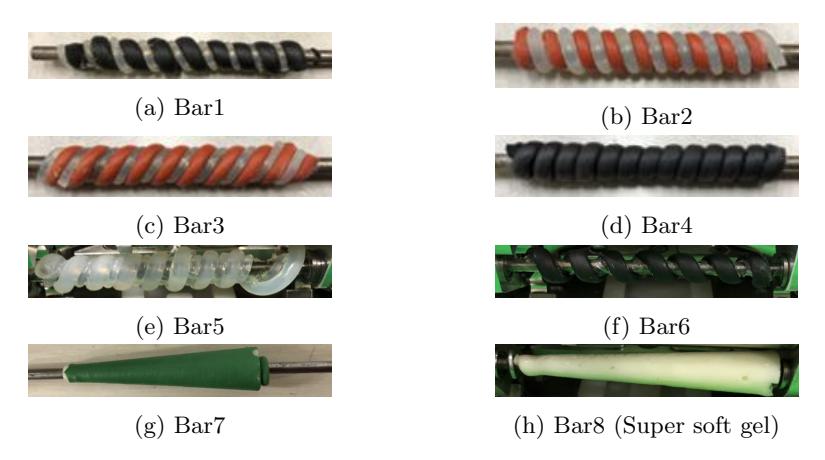
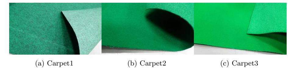
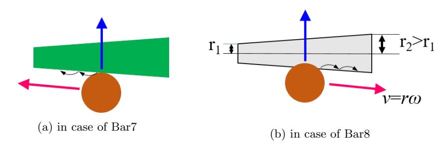
Table 1. Ball speed moving horizontally along dribble bar[m/s]
| Dribble bar\Materials | Carpet1 | Carpet2 | Carpet3 |
|---|---|---|---|
| Bar6 | 0.1 | 0.09 | 0.11 |
| Bar7 | 0.09 | 0.11 | 0.12 |
| Bar8 | 0.1 | 0.1 | 0.11 |
2.2 Tentative dribbling device
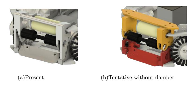
One of the problems with our dribblers is their low maintenance. Current dribblers consist of a ball sensor, dribbling mechanism, and tip kick bar in a single component, and improving any of them would require redesigning all parts. In this section, we evaluate the performance of a tentative dribbling device with improved maintainability by dividing the dribbling peripheral mechanism into a dribbling mechanism and a ball sensor & tip kick mechanism.
Verification of Shock Absorption Performance of Tentative dribbler
Conventionally, it is quite common to mount a damper on a dribbler. It is interesting to note that the ETDP2022 from Tigers Mannheim introduces a dribbler equipped with a 2 degree of freedom damper[6]. On the other hand, our recent damper unit has a problem that the dribbling bar bounces the ball during dribbling, so we removed the damper unit for trial and compared its behavior with two types of dribbling bars. One is made of conventional polyurethane rubber and the other is made of newly fabricated super soft gel. By comparing these two types, the possibility of simplifying the dribbling unit is investigated.
The following experiment was carried out to compare the shock-absorbing performance of two dribblers. A ball moving at a constant speed (about 2.3 ms$^{-1}$) was impacted head-on with a dribbler that was not rotating. The distance r between the robot and the bouncing ball was measured 50 times, the average was calculated, and compared for each dribbler. The ball was ejected using the slope shown in Fig.5(a), and the robot was fixed on the field. The measured distances are shown in Table 2.
Table 2 shows that the bounce distance of SUPER SOFT GEL is longer than that of the current dribble bar, with or without damper. This result indicates that the shock-absorbing ability of the super soft gel only is insufficient. As a result, it was shown that the tentative dribbling device has a lower shock absorption ability than the present device due to its structure without a damper. Namely, it was again confirmed that dampers are important to improve the performance of shock absorption.
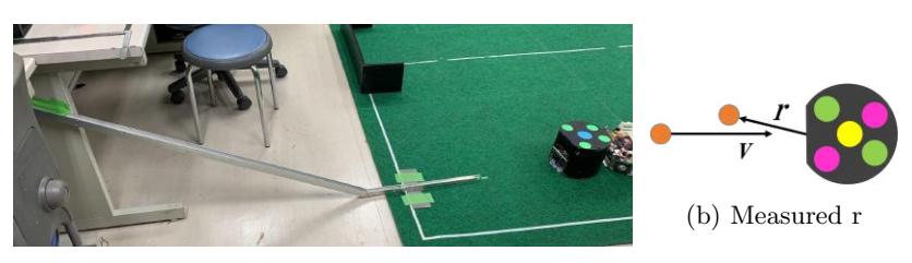
Table 2. Evaluation of shock absorption performance for dribbler
| Dribbling bar | Distance between robot and stopped ball [mm] |
|---|---|
| Current rubber with Damper | 379 |
| Current rubber without Damper | 600 |
| Super soft gel with Damper | 463 |
| Super soft gel without Damper | 819 |
Verification of ball keeping performance
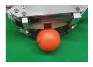
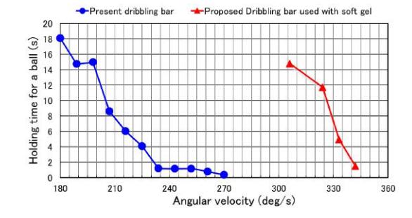
In real games, performance in possession of the ball (e.g., ball placement, preliminary movements before shooting, etc.) is critical. If fast and stable movement could be achieved while keeping possession of the ball, AI's tactics would be greatly expanded. The following experiment was carried out to compare the ball keeping performance of the dribbler described in the previous section. While the robot was keeping the ball, the robot was allowed to rotate until it released the ball at a constant angular velocity. The ball keeping time against the angular velocity of rotation was measured and compared between the present dribbler and the proposed bar used with super soft gel shown in Fig.6. The speed of the dribbling motor was about 100$^{-1}$ (6300rpm).
3 Electrical system
The main circuit was modified significantly last year. This year, we are continuing to use that circuit. In this section, especially, we describe a new circuit board for kicker device.
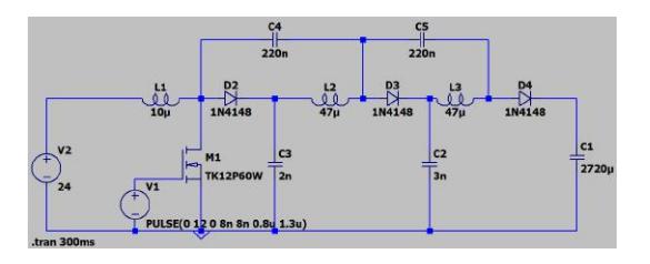
3.1 Introducing a New Kicker Circuit Using the Two-Step Booster Method
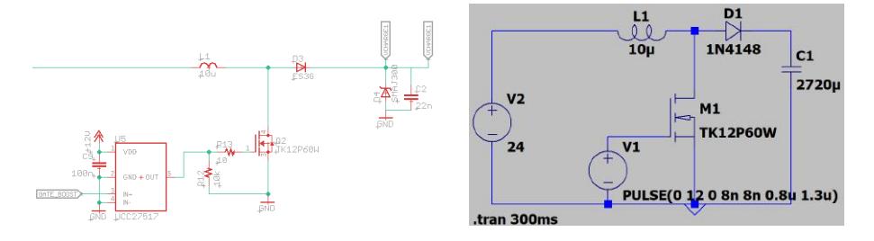
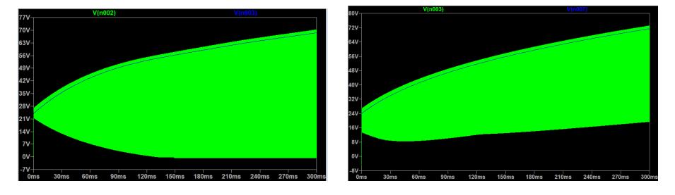
KIKS has conventionally used a one-stage voltage booster circuit as shown in Fig.8 as a kicker circuit to operate the solenoid. In this circuit, a reverse voltage equal to the voltage of the capacitor for the solenoid operation is instantially applied to the rectifier diode during the operation.
Recently, in SSL, the power of the kick and continuous operation have been required, and it has been necessary to increase the capacitor voltage when charging the device. Since our previous charging method applied a large load to the device, there were concerns about malfunctions during a game and a decrease in the circuit life. Therefore, we designed and introduced a new kicker circuit using a two-step boost method. It can be applied to the new main board introduced in ETDP[1] in 2022. The effectiveness of the circuit is described below.
4 Software system
(Section containing subsections)
4.1 Prediction of actions using machine learning
Predicting the actions of the opposing robot is one of the major factors that dominate soccer tactics, as it is useful in getting the ball and determining effective positioning. Our team, in particular, has the problem of low ball control during the game. To solve this problem, we tried to predict which robot the opponent robot will pass to next based on information from the field. In this section, we consider this problem as a classification problem of the opponent's behavior and analyze it using machine learning. We defined a total of 12 classes: 10 candidate classes for passing, and 2 classes for not passing (dribbling) and shooting.
Models and Data Structures In order to effectively learn information on a field, image classification methods are considered suitable. Therefore, we used one of them, ResNet (Residual Neural Networks)[7].
The input to ResNet requires a matrix representation of the field information. Since in the field of image classification, convolution is performed by superimposing two-dimensional images of each RGB and convolving them as threedimensional, we divided the field information into multiple dimensions and performed convolution. Here, the ball and each team's robot are represented as another 120$\times$120 matrix, each corresponding to a position on the field. For the team being trained, the value of the robot's angle and speed were similarly placed in the corresponding elements of the matrix, resulting in five matrices of field information.
ResNet is one of the CNNs (Convolutional Neural Networks), but it is generally considered unable to learn the positional relationships in an image. Therefore, to solve this problem, we added matrices representing $x$-$axis$ and $y$-$axis$ as field information in addition to the five matrices mentioned above, as proposed by Rosanne Liu et al.[8]. That is, a 7$\times$120$\times$120 matrix was used as input information to the model. The IDs used as output were assigned in $x$-$axis$ in ascending order to ensure uniqueness of IDs across data. The above dataset was used as the input to the model when the robot of the team being trained kept the ball. Then, the ID of the robot with the ball at the end of one play was used as the output of the model to create the teacher data. We played our AIs against each other on the GRSim simulator and generated data for 149 pass plays. Using those data as training data, training and inference were performed on the training and evaluation data, respectively.
The results are shown in Table 3. The results show that inference was not sufficient for the evaluation data. On the other hand, for the training data, it shows an accuracy of 80%, suggesting that the task is classifiable. Table 4 also shows the results of inference on the same training data under different conditions. From the table, it can be seen that the amplitude of velocity has a significant effect on the accuracy of inference, while the angle parameter contributes very little to inference. This means that it is almost meaningless in the data due to the fact that most robots are facing the ball direction. On the other hand, it can be seen that it works effectively with regard to the location matrix. However, when we experimented with increasing the number of data, we observed a decrease in accuracy. As a proposal for improvement to increase accuracy, we will consider using images or time-series data as input data. Md Amirul Islam et al.[9] demonstrate that the parameters of the Convolution layer can also be used to store location information, and we would like to try this out. In addition, in this section, we used inputs that represent coordinates with reference to CoordConv, but $xy$-$axis$ should originally be incorporated into the Convolution layer, and we will consider its implementation. After the completion of this model, we will apply it to actual matches and consider applications such as countermeasures for each opponent, or diversion of the opponent's passing algorithm to our team like imitation learning.
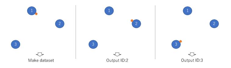
Table 3. Probability predicted by ResNet(149 samples)
| Data \ | Accuracy | Avg.Precision | Avg.Recall | Avg.F-measure |
|---|---|---|---|---|
| Learned data | 0.8055 | 0.7404 | 0.6251 | 0.6527 |
| Untrained data | 0.2564 | 0.0751 | 0.1138 | 0.0895 |
Table 4. Probability predicted by ResNet under the other condition
| Data \ | default | no speed, | no angle | no speed, | no position matrix |
|---|---|---|---|---|---|
| norm | norm, angle | ||||
| Accuracy | 0.8055 | 0.2592 | 0.8148 | 0.3611 | 0.6944 |
4.2 Verification of the effectiveness of position control performed by the robot itself
In this section, we try to improve the motion performance of the robot by controlling the position of the robot itself.
Problems with Global Vision Only Control At present, we are using global vision for position control based only on information from the server side. However, this method has the following problems.
– If the communication delay from the server to the robot is large, the robot oscillates back and forth due to the difference in the control cycles between the server and the robot.
– The robot cannot be controlled if there is a vision problem (e.g., the ball is in the robot's shadow and precise position information is not obtained) or if the communication is interrupted.
We tried to mount local vision on a robot in 2022 and reported on the utility of tracking the ball with local vision(Fig. 14) only and the control to support global vision[1]. In this section, we investigate the effectiveness of using an encoder attached to the motor in addition to local vision. In the following experiments, we try to control the robot's position using only an encoder.
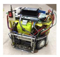
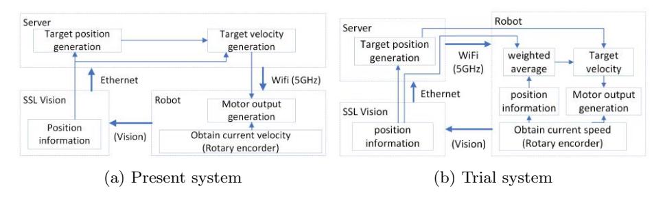
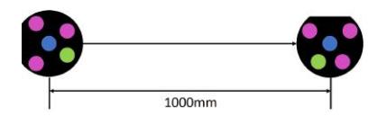
Table 5. Verification results (10 times average)
| Process time for \ Connection | Ethernet [ms] | Wifi [ms] |
|---|---|---|
| Ping between server and robot | 6.7 | 11.5 |
| Ping between server and vision | 2.2 | 6.1 |
| Present system | 2159 | >10000 |
| Trial system | 2060 | 1987 |
4.3 Trial experimetal in path planning based on Informed RRT*
At present, KIKS uses the Human-Like algorithm as the robot's path planning method. While the Human-Like algorithm is simple and fast, it sometimes fails to generate an optimal path when the path is blocked by obstacles or under some conditions. Therefore, in this section, we aim to introduce path planning based on Informed RRT*[10] and verify its effectiveness.
Experimental method In this experiment, the random place to place a point to generate the first path is somewhere in the range 14000 mm$\times$11000 mm with a margin of 1000 mm around a field of 12000 mm$\times$9000 mm, as shown in Fig. 17a.
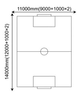
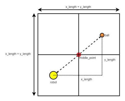
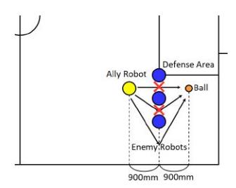
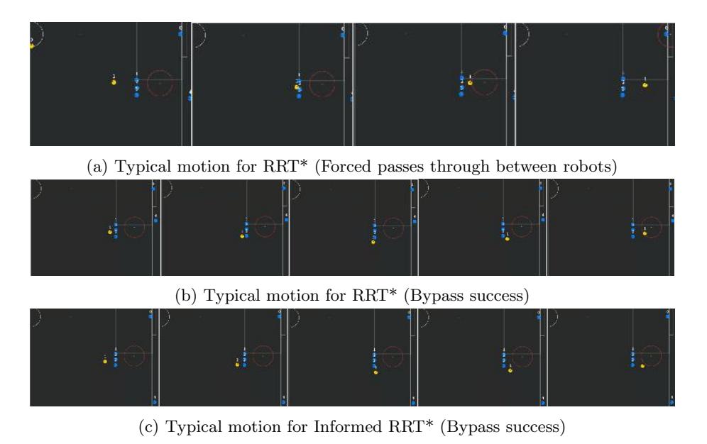
Table 6. Experimental results
| Path generation method \ Success rate | Rate of forced passes | Rate of | |
|---|---|---|---|
| for bypass(%) through between robots(%) Stoppage(%) | |||
| Human-like (10times) | 0 | 0 | 100 |
| RRT* (50times) | 38 | 12 | 50 |
| Informed RRT* (50times) | 92 | 0 | 8 |
Acknowledgments
This work was supported in part by JSPS KAKENHI Grant Number 20K03263, Grant-in-Aid from the Chuden Foundation for Education and The Nitto Foundation in Japan, respectively.
References
- Ryoma Mitsuoka, Yusei Naito, Yasutaka Tsuruta, Daichi Miyajima, Kosei Naito, Hironobu Suzuki, Ryuto Tanaka, Hayato Mitsuda, Yota Dori, and Toko Sugiura, KIKS Extended Team Description for RoboCup 2022; https://ssl.robocup.org/wp-content/uploads/2022/04/2022 ETDP KIKS.pdf
- Zheyuan Huang, Lingyun Chen, Jiacheng Li, Yunkai Wang, Zexi Chen, Licheng Wen, Jianyang Gu, Peng Hu, and Rong Xiong: ZJUNlict Extended Team Description Paper for RoboCup 2019, https://ssl.robocup.org/wp-content/uploads/2019/03/2019ETDPZJUNlict.pdf(2019).
- Nicolai Ommer Andre Ryll and Mark Geiger: TIGERs Mannheim Extended Team Description for RoboCup 2019, https://ssl.robocup.org/wp-content/uploads/2019/03/2019ETDPTIGERsMannheim.pdf
- Yusei Naito, Shin Ohno, Yuta Imaeda, Akihito Odanaka, Yasutaka Tsuruta, Ryoma Mitsuoka, Taisuke Tane, Masato Watanabe, and Toko Sugiura , KIKS Extended Team Description for RoboCup 2020; https://ssl.robocup.org/wp-content/uploads/2020/03/2020 ETDP KIKS.pdf
- HITOHADA Gel, https://www.exseal.co.jp/en/products/
- Nicolai Ommer, Andre Ryll, Mark Geiger, TIGERs Mannheim Extended Team Description for RoboCup 2022, https://ssl.robocup.org/wp-content/uploads/2022/04/2022 ETDP TIGERs-Mannheim.pdf
- Zifeng Wu, Chunhua Shen, and Anton van den Hengel, Wider or Deeper: Revisiting the ResNet Model for Visual Recognition, https://arxiv.org/pdf/1611.10080.pdf
- Rosanne Liu, Joel Lehman, Piero Molino, Felipe Petroski Such, Eric Frank, Alex Sergeev, Jason Yosinski, An intriguing failing of convolutional neural networks and the CoordConv solution, 32nd Conference on Neural Information Processing Systems (NeurIPS 2018), Montr´eal, Canada, https://proceedings.neurips.cc/paper/2018/file/60106888f8977b71e1f15db7bc9a88d1-Paper.pdf.
- Md Amirul Islam, Sen Jia, Neil D. B. Bruce, How Much Position Information Do Convolutional Neural Networks Encode? ,https://doi.org/10.48550/arXiv.2001.08248
- Jonathan D. Gammell, Siddhartha S. Srinivasa, and Timothy D. Barfoot, Informed RRT*: Optimal Sampling-based Path Planning Focused via Direct Sampling of an Admissible Ellipsoidal Heuristic, https://arxiv.org/pdf/1404.2334.pdf