OrcaBOT Team Description Paper 2023
Chayud Srisumarnk, Nattapol Chiewnawintawat, Tanabun Khumsapy, Yanisa Wunvisut, Sivakorn Seinglek, Tongthai Thongsupan, Thapanee Pandang, Nutchanon Siripool, Natsongwat Yorsangrat, Angkoon Angkoonsawaengsuk, Leon Wirz, Phatham Loahavilai
Sirindhorn International Institute of Technology, Thammasat University, Rangsit, Thailand
https://siit-robocup.netlify.app/
Abstract This paper describes the detail of the proceeding Small Sized League robots from the newly established OrcaBOT team under Academy club at Sirindhorn International Institute of Technology, Thammasat University, Thailand. The paper shows the detail of our first robot design and its contributions in term of mechanical design, electrical design and software design as well as to explain how we have integrated the existing open-source material to construct the soccer robot team in our first and limited time. The system results and further discussion are also included in this paper. Those will express and illustrate our plan for the development goal which we aim to be achieve in this year in RoboCup 2023.
1 Introduction
OrcaBOT is a newly established team from Sirindhorn International Institute of Technology (SIIT), Thammasat University, Thailand. The team consists of twelve members which include students from Computer, Digital, Mechanical, and Electrical Engineering fields of study. Our team was extensively inspired by the RoboCup Competition that was hosted in Bangkok during the year 2022. The event motivates us to build a team with varieties of members with the goal and aim to participate in RoboCup 2023 and make a fundamental robotic competition pipeline for the newer generation SIIT students the future. As a newly created team, we have been working towards the creation of our first soccer robot as efficient as possible to satisfy the requirement in the upcoming RoboCup registration. This paper will explain the development, the details, and our expectation by this 2023 competition which cover both the hardware and the software aspects as well as how we conduct our strategy and working pipeline in order for us to achieve our goals and the competition requirement within a limited amount of time and resources. We would like to also dedicate this paper to the newly established teams in both Thailand and foreign countries as this could be a potential guideline for them to follow and further improve and expand our progress and the robotic communities as a whole. Moreover, OrcaBOT is also a team under the Academy club at SIIT that is solely dedicated for robotic enthusiasts to participate and expand their knowledge as well as to enjoy in the path or journey in the robotics world. We would like this team, OrcaBOT, and the paper to be a role model for those who are interested in the path of the robotics domain.
2 Mechanical Design
This section of the paper will illustrate about the modification of mechanical structure with respect to any citations. This is a prototype of our robot to suit the competition requirement. However, we have planed to perform some changes in our design before submitting the final team description paper and to be ready by the start of the competition in this year. The core design concept of our work will remain the same and explained in the following subsections.
2.1 Core Structure
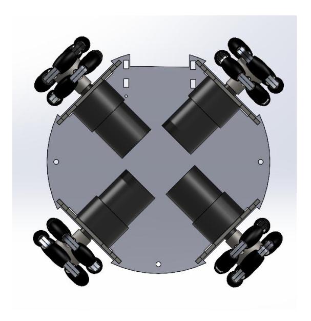
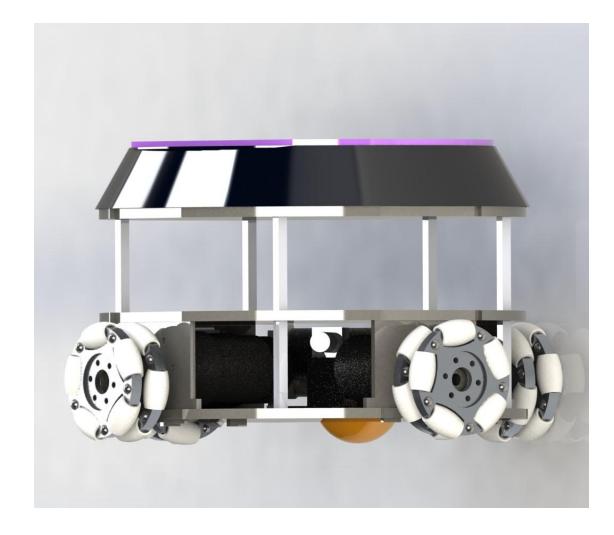
The soccer robots were initially design with the base structure. According to the figure 1, 90-degree configuration base is used for the stability of the robot movement and foundation of our robot design. By using this configuration with the current motor specification, there will be a limitation of space in the first floor. We thus currently design the left center area to be the space for the motor wiring placement instead of putting any components in it. In term of the driving hardware structure, the first floor consisted of dribbler, solenoids, and four motors. Each of them are locked by motor-base which are supporting the second floor as shown in a figure 2. Moreover, motor-base is also used to lock second floor in place and make it undoubtedly strong. Second and third floor are mainly for the electrical circuit and battery placement. Each floor is supported by poles that are grounded on the first floor.
2.2 Wheel
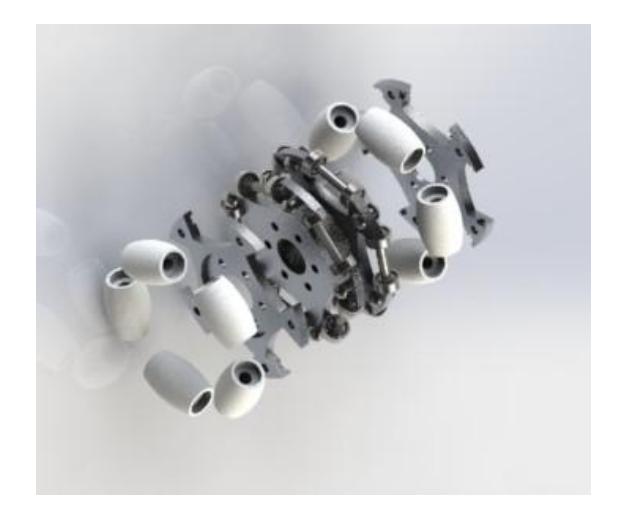
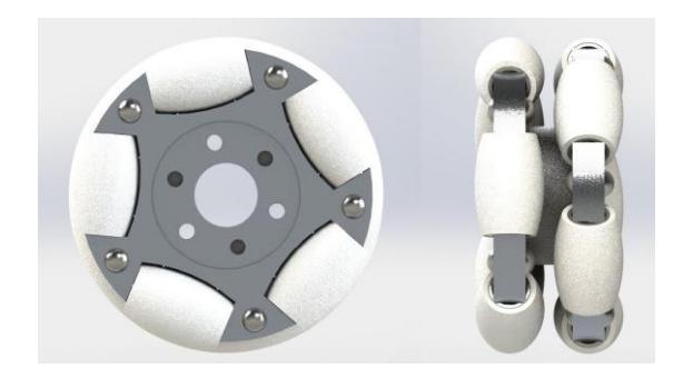
For the wheels, friction is responsible for most of the robot movements. Therefore, it is important to consider a bigger contact area due to the relation between friction and area as a figure 3. The more contact area, the better for the resulting traction. So, two-layers omni-wheel is used to increase the surface area and improve the traction for better responses of the movement. We, the mechanical team section then proposed our own designed with more suitability for the current hardware specification as in figure 4 and 5. However, due to the limitation of time, the omni-wheel are bought to be used in prototypes with the considering on the ones that are closest to our initial specifications to test the feasibility of our robot and planning to be replaced by our own design in this very near future.
![Fig. 3. Graph of relation between friction and area [5]](/tdps/soccer_smallsize__2023__OrcaBOT/_page_3_Figure_1.jpeg)
2.3 Ball Dribbler
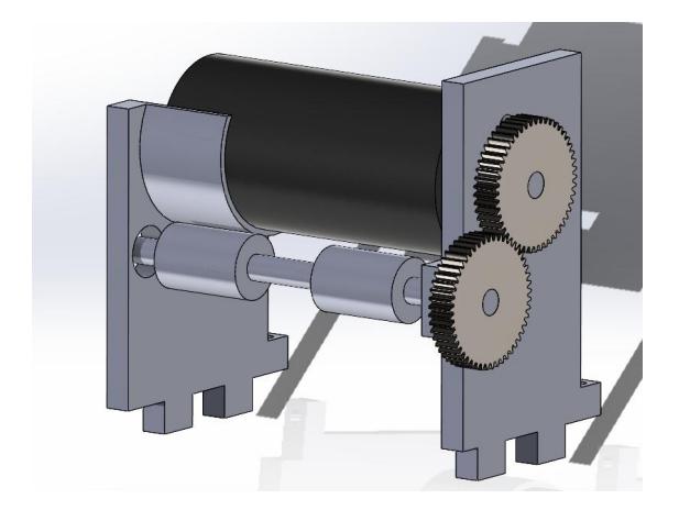
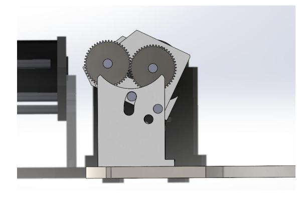
There are two tested designs and concepts for the dribbler. The first design has a fixed position of the roller as in figure 6. According to the SSL rules, the ball can be cover by 20% of the dribbler. This rule has influence the position design of the roller. Our experiments and research found that the distance from the dribbler roller to the ground that is 41 mm.[3] which also work for our design. The roller divided into two parts that made of neoprene rubber. This material increase the friction between the ball and the roller. The separated roller has a space to trapped the ball in the center. This design has a good grip on the ball in the stationary state. Meanwhile, it has a dropped performance when the robot is in the moving state. For the second design, it has a slot which can dynamically move to catch the ball[2] as a figure 7. For the roller, high friction materials are used to made the roller. Those materials are neoprene rubber and molding acrylic. However, if the roller surface isn't smooth, it can cause the vibration and unstable which affects the ability of the robot to catch the ball which consider to be one of the challenge to be improve by this competition period.
2.4 Design Improvement Plan
These improvements were planned to be conducted during the gap time from the TDP submission date to the beginning of the 2023 competition.
Space Management First of all, to increase a vacant space on the first floor, the wheel size need to be reduce and it will be an one-layer omni-wheel. For the contact area between the wheel and the ground issue, sub-wheel will be increased. To minimum the center of mass, the battery will be place on the first floor instead.
Dribbler As for the dribbler, we would like to experiment different dribbler roller geometries to improve the gripping performance. Also, considering suitable coating materials such as silicon for the roller. We are interested in implement a damping system to prevent from the vibration and unstable motion from the dribbler. In addition, we will add a cover for dribbler gears transmission to prevent from the ball collision which could cause gear misalignment in the first dribble design. We also planning to add component to make the robot to be able to float the ball, this idea has been added in concept but due to some technical problems, we didn't add it in prototypes.
Solenoid Kicker We will optimize the speed and the kick power of the solenoid by testing several solenoid coil. We would implement a chip kicker for more option of ball passing skill and also increase the contact area between the ball and the roller.
3.1 Microcontroller Unit(MCU)
This work utilizes Arduino DUE with 32bit CortexM3 ARM microcontroller processor, instead of using the STM32 series microrcontroller. From several tests, we found that Arduino DUE with ARM architecture is powerful and fast enough to perform the task required in SSL RoboCup competition along with the simpler setting procedure and more familiar development tool. However, STM32 is still more custom-able in terms of software and electrical circuit design. Our team then have decided to meet between custom and preset electrical structure by designing the printable circuit board (PCB) with the pins that allow the Arduino DUE to plug-in to the broad instead of embedding the MCU directly to prevent issues from redesigning or fixing the circuit board as there are still multiple of experiments needed for our robot. This design will additionally help solve the STM32 shortage in our country and international shipping time cost. The robot control system uses pins and power based on this Aruidno DUE structure [4]. The circuit design will be further discussed in the consequent subsection.
3.2 Main Board Design
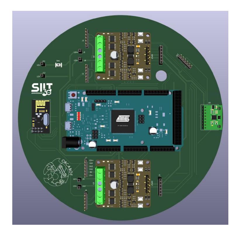
The main board design in this robot is based on hardware limitations that can find in local Thailand. Based on the regulation, the robot should not exceed 180 mm in diameter, so we designed it based on that regulation. The PCB is a superficial 2 layers with 1.6mm thickness as shown in figure 8. As we tell in the previous section, the central processor used in this robot is Arduino DUE with a 32-bit CortexM3 ARM microcontroller processor. We use 2 Cytron MDD3A - dual-channel 16V / 3A motor controller for the motor driver model. For the communication module, we use NRF24l01. Based on this module, we fit all these modules into the PCB. The PCB is designed so all modules can be removed easily in case any malfunction.
3.3 Kicker Circuit
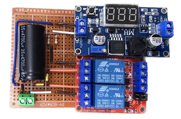
The kicker circuit receives the signal from the MCU and powered the solenoid kicker by controlling the 2-channel 5V relay switch. The relay board plays the role on the electric power flow control that stored in the 35 Volt 4700 uF capacitor and further send to the step up voltage and Buck converter from 5 to 35 volt which increase the kicking power ability of the robot. Lastly, the circuit will send the power to active the 12V 10mm DC solenoid. The kicker circuit implemented is shown in figure 9.
4.1 System Overview
The system for the robots to perform the tasks consists of two major levels including high level decision system and low level control system. The high level system is a group of software that take input from the field cameras and compute the action decision of each particular robots in the field. Staring from the camera, we setup and calibrate the open-source SSL-Vision software that can receive the signal from multiple cameras on the field and perform the image recognition to detect the position and ID of each robot. Then the computer vision system will send the detection information for the strategy software to decide the best possible action on each robot to get the score from the soccer competition. After the action decisions have been created by the strategy software, they will be sent to the low level control system via the radio communication module. On the low-level control system, it is conducted by Arduino IDE with C/C++ language-based development. The system allows the robots to receive multiple different control within a single file of code and finally to perform its tasks which will be discussed in the subsections.
4.2 SSL Vision
Our system utilizes the open-source software SSL-Vision provided by the SSL community and is used to receive data from the camera. This allows us to obtain the positions of all robots and the ball which we then use to send a message to our strategy program. We drew inspiration from the python-ssl-client open-source codebase to design our program, which listens for messages, generates a JSON file for communication with the strategy program, and displays them in the console.
Regarding the information from SSL-Vision, it provides us with two types of data packets: detection data which includes detection results from robots and balls captured by the camera, and geometry data which includes information such as field dimensions. Some parts of the latter can be obtained through camera calibration which can be performed using SSL-Vision.
4.3 Strategy Design
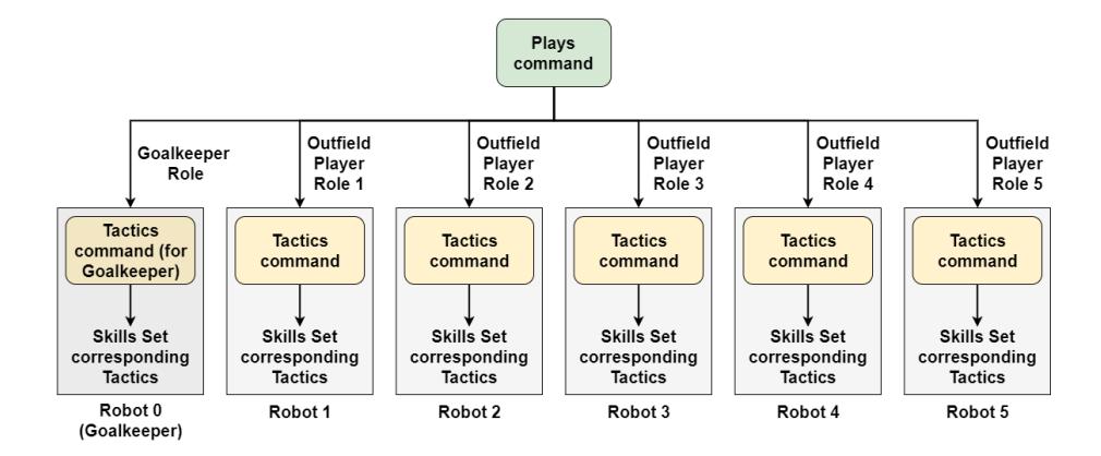
Our strategy program is primarily constructed using the Python ROS library. The strategy design is based on the principles of STP architecture [1]. In the implementation, the architecture includes two groups: the solitary goalkeeper and the team of outfield players. Each group has its own set of commands, and some communication occurs between both groups.
As shown in Figure 10, the strategy system is divided into three layers: Skills, Tactics, and Plays. This creates a hierarchy for team control. The details of each layer and their work are as follows:
Skills
The Skills section is responsible for low-level actions performed by an individual robot, either by commanding it directly through motion control or through navigation. It interacts with the world state to adjust robot control parameters and sends a message to the communication panel, then provides commands to robots. The Skills section comprises two components: sensory processing, which utilizes or generates the necessary sensory predicates from the world model, and command generation, which determines the actions the robot performs. Examples of the skills include kicking, moving, and turning in specific directions.
Tactics
The Tactics layer encompasses a single robot's behavior as a higher level of action. It is composed of a set of skills and determines which skill or set of skills will be executed by each robot. Furthermore, it includes evaluation routines to verify if the tactics have been completed. The Tactics layer determines which skills will be employed and sets the parameters for their execution. Each tactic includes an algorithm with layers of skills that respond to conditions in the world state, and the algorithm initiates actions through the execution of skills. Each tactic may also store any local state information it requires for proper execution. Examples of Tactics include point-to-point passing, shooting, and marking opponents.
Plays
The highest layer is the Plays layer. It combines multiple tactics that are executed dynamically. This layer establishes the central command, which includes a joint policy for the entire team. The components include execution details to help guide the play execution system, and roles, which describe the actual behavior of each robot. Each play assigns roles to robots to carry out specific actions. Examples of Plays include defense play and attack play. Additionally, we plan to work on play commands in set piece game states.
Regarding the development, the system is developed from open-source codes based on the STP architecture. The strategy program determines the playstyle and tactics based on the positions of each robot and the current situation, using information received from the vision section. Additionally, we utilize the grSim software provided by the SSL community as a console and graphical client for better visualization of the game.
4.4 Communication
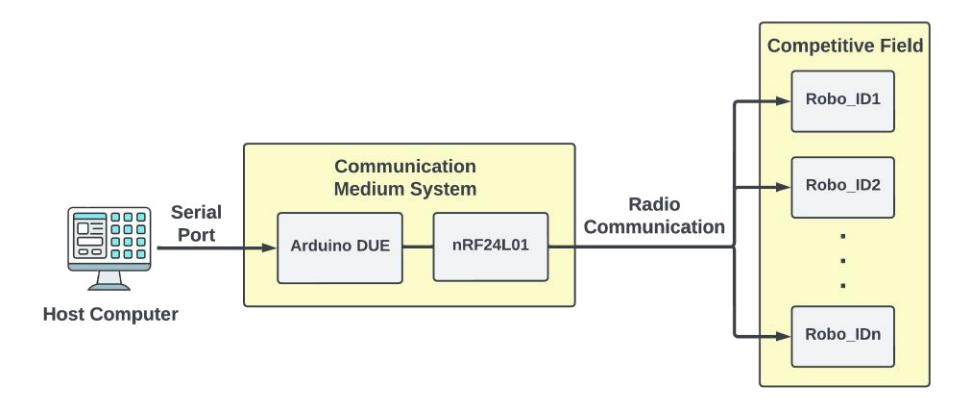
To allow the strategy software to send the command to each particular robot, we use the 2.4GHz radio communication for the robots and the host to send and receive command between each other. By using a nRF24L01 radio frequency module with an Arduino DUE as a communication medium, we were able to send the command with respect to each particular robot ID to each robot simultaneously. This communication medium station connects to the host computer to take the packet from strategy software via serial port and send them to each robot as the diagram in figure 11. Hence, the communication latency between the host and the robots is acceptable which leads the robots to work smoothly in term of communication as Robles et al. [6] recommended. This communication speed allows the low-level system on the robot to extract the command and perform its task in the expected period of time.
4.5 OrcaBOT Control System Tester (OCST)
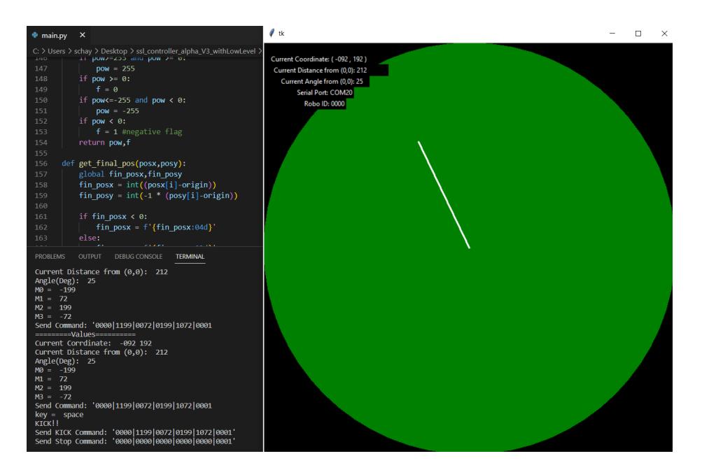
We proposed the development of the Python-based graphical user interface(GUI) software to test our end-to-end robot control system called OrcaBOT Control System Tester or OCST. The OCST consisted of the simple mouse and keyboard controllable interface with circle shape that receive the mouse coordinates as the one major input and can show the output on the terminal as in figure 12. The mouse coordinates allow the software to calculate the distance and the angle vector from the middle of the circular control space in the program window. Moreover, the program also able to receive the signal from the keyboard as the representation of the robot actions. The program send the command as the calculated power of each motor and the robot ID using PySerialTransfer library to the communication system which than convert to robots' readable commands and send to each of them.
5 Expectation of Completion
As a new team, this section will express our current capability and the expectation of our robots team which are to be completed before the competition begins. For the current capability of the robots, the structural design and the hardware components work smoothly and following the general requirement that the robots need to be qualified first in order to be able participate in this competition. Only few adjustments are needed to improve the performance to suit for the real competition. The low-level control system is also considered to be finished as the robots are able to communicate and receive the command from the host and translate the commands with each particular robot ID to perform actions. In addition, our robots control system can perform all the actions that are needed for the competition which includes Holonomic drive movement, ball dribbling and ball kicking. In term of high-level control, we have generally done and setup the basics for the SSL-Vision as well as the field setup and designed the principle of the playing strategies along with its open-source software as discussed in section 4.3. However, our main challenge now is the connection between three main high-level sections which are the connection between SSL-Vision to the strategy software and from the strategy software to the robot communication system. These three parts and its connection structure design were already prepared which means that the only major part left is the implementation of the high-level software connections. Therefore, with the partial high-level implementation and small hard design improvement needed, we are confident to be finished before the competition starts and be ready to participant in this RoboCup 2023 event.
6 Acknowledgement
We would like to thoroughly express our dearest gratitude towards the financial sponsorship provided by student affair division of SIIT as well as to gratefully acknowledge Assoc.Prof.Dr.Paiboon Sreearunothai for being our club advisor and Asst.Prof.Dr.Itthisek Nilkhamhang, Dr.Somrudee Deepaisarn and Dr.Maroay Phlernjai for being our technical supports throughout the course of this robotic development.
References
- Browning, B., Bruce, J., Bowling, M., Veloso, M.: Stp: Skills, tactics, and plays for multi-robot control in adversarial environments. Proceedings of the Institution of Mechanical Engineers, Part I: Journal of Systems and Control Engineering 219(1), 33–52 (2005)
- De Leon, J.M., Tan, M., Piel, J., Oh, H., Ademolu-Odeneye, I., Woldeghebriel, E., Gonzalez, R., Sales, P., Guter, W., Heinle, D., et al.: Mit roboteam 2020 team description paper
- De Witte, J.: Mechatronic design of a soccer robot for the small-size league of robocup. Master's thesis, Vrije Universiteit Brussel (2010)
- Due, A., Core, A.: Arduino due. Retrieved 9(16), 2019 (2017)
- Enachescu, M., Van den Oetelaar, R., Carpick, R., Ogletree, D., Flipse, C., Salmeron, M.: Observation of proportionality between friction and contact area at the nanometer scale. Tribology Letters 7, 73–78 (1999)
- Robles, P.R., Aubel, M., Pe˜na, N.H., Alvarez, J.: Mechanical, hardware and firmware considerations for a robocup ssl robot. In: CRoNe. pp. 11–17 (2019)